4
ATM Network Management Architecture
4.1 Introduction
Network management functions are identified by the ISO in the management framework of the well-known OSI management model [1]. These functions can be classified into five areas as follows:
1. Configuration management: Configuration management involves de-termining what is in the network and manipulating those compo-nents to keep network interconnections and services up and running. 2. Fault management: Fault management encompasses detecting,
isolat-ing, and correcting abnormal network behavior. Due to the growing importance of the network in an enterprise, any interrupt of network services may affect the operation of the whole organization. Conse-quently, fault management is considered the most significant network management function.
3. Performance management: Performance management evaluates net-work behavior and effectiveness. Its aim is to understand how the network operates under normal and abnormal conditions. By moni-toring the statistics of network components, the performance of a net-work can be fine-tuned, hence improved.
4. Security management: Security management deals with the monitor-ing, control, and protection of management information on the network from unauthorized or accidental access, disclosure, or modi-fication. This functional area is also responsible for the management
of security facilities, including control and monitoring of them. Proper security management should log and report security threats or breaches.
5. Accounting management: Accounting consists of allocating costs among network users. This function includes collecting network us-age information, setting accounting limits on network usus-age, and re-porting on costs incurred.
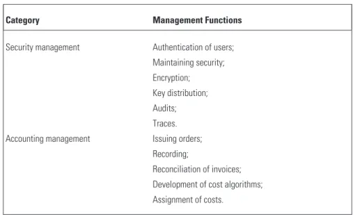
A summary of network management functions for each category is given in Table 4.1. A detailed description of these functions can be found in [2]. The management functions are performed with the management plane of the B-ISDN protocol reference model. This book focuses on configuration, fault, and performance management. In Sections 4.2–4.4, the frameworks for ATM network management as well as ATM-specific management requirements will be introduced.
Table 4.1
Network Management Functions [3]
Category Management Functions
Configuration management Network status monitoring; Network routing;
Parameter database; Configuration control; Facility control. Performance management Monitoring;
Analysis;
Database generation analysis; Reporting;
Tuning.
Fault management Event notification; Logging; Ticketing; Tracking; Isolation; Resolution.
Category Management Functions
Security management Authentication of users; Maintaining security; Encryption; Key distribution; Audits; Traces. Accounting management Issuing orders;
Recording;
Reconciliation of invoices; Development of cost algorithms; Assignment of costs.
4.2 ATM Network Management Reference Model
Figure 4.1 depicts the ATM network management reference model specified for end-to-end ATM network management by the ATM Forum’s network management subworking group [4]. This model describes the various types of network management needed to support ATM devices, private networks, pub-lic networks, and the interaction between them.
Management system Management system Management system Private ATM network Public ATM network Public ATM network M3 M5 ATM device M1 M2 M4 M4 Public UNI Private UNI BICI
The five key management interfaces defined in this framework—labeled M1 through M5—are all essential for end-to-end monitoring and control. They are described as follows.
• M1: The management interface between the private management sys-tem and the end ATM device (i.e., between an ATMworkstation(WS) and the management system);
• M2: The management interface between the private management sys-tem and the switches making up the local private ATM network; • M3: The management interface between the private management
sys-tem and the public management syssys-tem;
• M4: The management interface between the switches in the public ATM network and the public management system;
• M5: The management interface between two public management sys-tems from different carriers.
M1, M2, and M3 embrace the Internet management framework, i.e., SNMP [4, 5], as it is the most widely deployed network management frame-work. SNMP is both the de facto and the de jure standard for today’s private/ enterprise network management, although many other protocols are also use-ful, particularly Telnet and theInternet control message protocol(ICMP).
M1 and M2, which define the interface between thenetwork management system(NMS) at the customer site and an ATM end-station or a private net-work switch, are of special interest for managers of enterprise netnet-works. M1 and M2 interfaces encompass the relevant standard MIBs for the physical layer, ATM layer, and higher layers such as DS-1, DS-3, SONET/SDH, AToM MIB, and the MIB-II as defined by the IETF. The AToM MIBs and SONET/SDH will be described in Chapters 6 and 7, respectively. The AToM MIB allows network managers to group collections of switches, virtual connec-tions, interfaces, and services into discrete entities and is SNMPv1- and SNMPv2-compliant.
Also encompassing these MIBs is the M3, thecustomer network manage-ment(CNM) interface. M3 describes the interface between the customer and carrier management systems that gives the customer a view into the carrier’s network. M3 allows customers to supervise the use of their portion of a public ATM network. Ultimately, carriers plan to extend their CNM offerings so that the network managers can have real-time control over the services they use.
CNM for ATM public network service has been specified by the ATM Forum and will be addressed in Section 4.3.
Today, most LANs and the applications that run over them are SNMP-manageable. By making use of SNMP for M1 to M3, the management of pri-vate/enterprise networks is unified on SNMP framework, allowing existing management systems to work seamlessly with ATM NMSs, facilitating an inte-grated management for network, systems, and applications.
M4 is the management interface needed to manage a public network serv-ice, including both network element (NE) management and service manage-ment functions. This interface enables network and network elemanage-ment views from a carrier’s NMS into the public ATM network it manages. Unlike private networks, public networks are committed to supporting the TMN where the
common management information protocol (CMIP) has been adopted as the standard for transferring management information. As such, M4 is specified in such a way that different approaches can be used, including SNMP, CMIP, and possibly other emerging schemes. For each view, a logical MIB that speci-fies the management interface requirements is developed first. The purpose of defining a logical MIB is to provide a common frame of reference for the devel-opment of protocol-specific MIBs such as those based on CMIP or SNMP. The definition of protocol-specific MIBs from a common logical MIB should facilitate their potential coexistence within a public carrier’s network. The ATM Forum has already developed the CMIP MIBs for both views.
M5 is the most complicated interface in the reference model since it is the management interface between NMSs from different carriers. There is no stan-dard available for this interface yet.
Though the M2, M3, M4, and M5 management interfaces provide a top-down network view, they are not the only management functions relevant to ATM. The ILMI provides an ATM link-specific view of the configuration and fault parameters of an ATM interface. In addition, an ATM interface pro-vides some layer management functionality by way of the OAM cells, which are detailed in Section 4.4. Customers can consider ILMI to be a CNM service since it allows information retrieval from a public network. However, the ILMI is embedded in the ATM interface and must be accessed by equipment directly connected to the interface. In contrast, the M3 interface allows direct access by customer premises-based management systems to CNM devices. ILMI will be introduced in Chapter 5.
There are also a number of SNMP MIBs that are defined to manage higher-layer functions or services running over ATM networks. These MIBs include LANE MIB, private network-network interface MIB,circuit emulation
service(CES) MIB, anddata exchange interface(DXI) MIB. Chapters 8 and 9 will be devoted to LANE MIB and PNNI MIB, respectively.
ATM remote monitoring (RMON) further enhances the manageability of ATM networks by adding high-level SNMP traffic monitoring capability to ATM systems. Based on RMON-standard MIBs, the ATM RMON MIB extends traditional RMON data sets such as flow statistics, host, and traffic matrix to ATM networks. This MIB allows a network manager to monitor net-work traffic for fault and performance monitoring and capacity planning.
4.3 Customer Network Management
CNM is a new service offered to customers by a telecommunications service provider (i.e., a career) that allows customers to access management informa-tion and funcinforma-tions existing within the provider’s domain that relates to tele-communications services provided to the customer. CNM provides near real-time information about telecommunications parts of the network, ena-bling the private NMS to build and maintain a coherent, end-to-end view of the private network, its services, and performance. The functions in a typical CNM scenario [6, 8] are listed in Table 4.2.
Table 4.2
Typical CNM Functions (Copyright CiTR Pty Ltd.)
Category Functions
Fault management Reporting, tracking and resolution;
Interface to customer trouble ticket or workflow system; Fault domain identification.
Configuration management View inventory ofcustomer premises equipment (CPE) and services provided by telecommunications provider; Order new services;
Reconfigure services and network.
Accounting management Expenditure tracking on services in near real time; Interface to customer accounting system;
Extract of histories and usage profile by customer cost center, budgets, and authorization;
Category Functions
Performance management Monitoring of QoS parameters such as throughput, delay, and availability;
Generating reports and verifying them against service contract;
Performance comparison of rival telecommunications services.
Security management Access authentication and authorization; Separation of carrier’s and customer’s data.
Given the diversity of services that a single customer may use and the vari-ety of systems at the customer premises, a standardized interface is necessary for the exchange of management information. Figure 4.2 shows the architecture of CNM, in which the public network provider offers CNM service via a CNM agent in the provider’s network. The CNM agent is, in turn, associated with an MIB that provides the required management information to the customer.
The carrier’s network is monitored and controlled via its own NMSs. Part of this network is leased to customers to form part of their core enterprise net-work. Service-related information is passed from the carrier’s NMS to the carri-er’sservice management system(SMS). Each of the management entities within the carrier’s system interacts with an agent adaptation function to update status in the carrier’s CNM agent MIB. These systems include the carrier’s account-ing, NMS, SMS, or any other relevant carrier’s legacy system. The function of the agent adaptation is to extract data from the different carrier sources. This is merged in the carrier’s CNM MIB. The enterprise CNM manager receives alarms from the carrier’s CNM agent, and the manager applications provide the necessary functionality to interface to the CNM agent MIB. Thebusiness management system(BMS) is involved in online reconfiguration and provision-ing of new services.
There are some fundamental differences between traditional network management and the CNM [8]. First, the customer’s NMS has only limited access to the information provided by the service provider. The service provider is responsible for managing the entire shared network as a whole, while service customers only view and manage their individual portions of the shared service. Because they have a restricted view of the network, customers are unable to
SNMP-Based ATM Network Management Enterprise CNM management platform BM adaptation SM adaptation NM adaptation Enterprise BM Enterprise NM Custom CNM database Enterprise network Application CNM agent CNM request handler Service traffic
Custom Domain Career Domain
BM: Business Management SM: Service Management NM: Network Management BM system SM system NM system Career CNM database Carrier network
perform certain network management functions in the shared environment. For example, a customer that sets routes for optimized throughput of its own traffic may disrupt another customer’s traffic. Only the service provider, with a complete view of the entire network, is in a position to determine routes that allow provisioned access to network resources for all customers.
Another fundamental difference in management functionality is that service providers manage the network internals directly, while customers man-age their portion of the shared network indirectly. The service provider is responsible for the overall operation of the shared network, so any management control offered to customers must first be approved by the service provider before the control request takes effect in the network.
Finally, while service providers see a physical view of the network, cus-tomers see a logical view. This logical view includes the customer’s configura-tion of service access points (i.e., logical ports) and the virtual connecconfigura-tions that run between these logical ports. The customer does not see the individual net-work switches along the paths of its virtual connections, as the establishment of physical routes is a responsibility of the service provider.
The ATM Forum’s M3 interface specification, “Customer Network Management for ATM Public Network Service” [4], defines CNM require-ments, interface specification, and object definition for ATM permanent vir-tual connection service. The M3 specification only deals with network management; neither business nor service management functions have been defined. The agent’s MIB models an ATM network as a large distributed switch by hiding all the network’s internal connectivity as being internal to the distributed switch. Consequently, each concatenated virtual link that makes up a part of a virtual connection through an ATM public network is modeled as a virtual segment. With the M3 interface a customer is provided a view of a vir-tual ATM network that shows the customer’s logical portion of the network.
Taking into consideration the differences between traditional network management and CNM, requirements for the M3 interface are classified into two categories to allow public network providers to offer modular incremental capabilities to meet different levels of customer need. Class I functions only provide read-only monitoring information, while Class II functions offer cus-tomers the ability to add, modify, or delete virtual connections and subscrip-tion informasubscrip-tion in a public ATM network.
The management framework to be used for M3 interface is the SNMP. The M3 interface specifies the use of MIB modules as shown in Table 4.3. All the modules are defined by the IETF; no new MIBs are defined by the forum for CNM.
Table 4.3
MIB Modules used for the M3 Interface
Layer RFC No. Abbreviation Name
Transport and network
RFC 1213 MIB-II Management Information Base for Network Management of TCP/IP-Based Internets: MIB-II RFC 1573 MIB-II Evolution Evolution of the Interfaces
Group of MIB-II
AAL ATM RFC 1695 AToM Definitions of Managed
Objects for ATM Management, Version 8.0 Using SMIv2 Physical layer RFC 1595 SONET/SDH Definitions of Managed
Objects for the SONET/SDH Interface Type
RFC 1406 DS3/E3 Definitions of Managed Objects for the DS3/E3 Interface Type RFC 1407 DS1/E1 Definitions of Managed
Objects for the DS1 and E1 Interface Types
4.4 Operation and Maintenance Functions
OAM is an integral part of a communications network. ATM provides an unprecedented level of OAM support by offering OAM functions at every level of the physical layer and ATM layer. ITU-T I.610 [9] specifies OAM principles and functions for B-ISDN.
In general, OAM functions deal with the following aspects of a network:
• Performance monitoring: Monitoring the normal operation of the managed entity by continuous or periodic checking of functions and collection of performance statistics;
• Defect and failure detection: Detecting malfunctions or predicted mal-functions by continuously, or periodically, generating various alarms;
• System protection: Excluding a failed entity from operation by block-ing or changblock-ing over to other entities, so that the effect of failure of a managed entity is minimized;
• Failure or performance information: Transferring failure information to other management entities automatically or upon request;
• Fault localization: Identifying a faulty managed entity by an internal or external test system, if failure information is insufficient.
OAM functions in an ATM network are focused on performance moni-toring, defect/failure detection, and localization, which can be categorized into performance and fault management. These functions are performed on five OAM hierarchical levels associated with the ATM and physical layer of the pro-tocol reference model. The resulting bi-directional information flows F1, F2, F3, F4, and F5 are referred to as OAM flows [9], as shown in Figure 4.3. Note that not all of these flows need to be present. The OAM functions of a missing level are performed at the next higher level by the layer management entity. This does not mean that all OAM functions can be done at the highest level (consider, for example, F5). The purpose of including OAM flow at each level is to facilitate fast identification/recovery of fault conditions at each level. For example, once a fault condition is detected by physical layer OAM flows, the physical layer system will switch the service to a spare protection line so that the service is not interrupted. ATM layer OAM flows, which are shown in Table 4.4, are performed by special ATM cells known as OAM cells. The F4 and F5 flows give ATM network devices the ability to gather information about end-to-end connections.
4.4.1 Fault Management
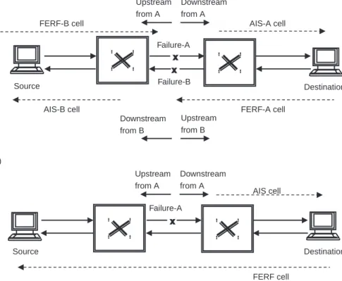
Two types of ATM OAM cells,alarm indication signal(AIS) cells and far end reporting failure(FERF) cells, have been specified for fault management, which communicates failure information throughout the network. The operation of AIS and FERF cells is illustrated in Figure 4.4.
Whenever an ATM switch fails and a VP or VC is interrupted, each adja-cent switch in the network automatically generates an AIS cell and sends it to all downstream switches. The AIS cell alerts the other switches in the network of the failure and gives them the opportunity to devise alternate routes for vir-tual connections that would normally cross the failed switch. FERF cells are
sent to the far end from a virtual connection endpoint as soon as it has received VP-AIS cells or detected connection failure.
The ATM Forum has also defined a fault management cell for continuity checking. When a VPC/VCC is idle for a certain period of time, end-stations or switches involved in the connection can send a continuity check cell to verify that the connection is still up.
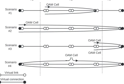
In addition, an OAM back capability, which uses a special loop-back cell, has also been specified for verifying connectivity and diagnostic problems that AIS or FERF cells cannot. The loop-back cell supports four loop-back scenarios as depicted in Figure 4.5, providing preservice connectivity verification, VPC/VCC fault sectionalization, and on-demand delay measure-ments. The loop-back capability is nonintrusive, which means that the loop-back test can be done online, without having to take the virtual connec-tion out of service.
Virtual channel connection Virtual channel link
Virtual path connection Virtual path link
AT M la y e r Ph ysical la y e r Transmission path Digital section Regenerator section F5-Virtual channel level F4-Virtual path level F3-Transmission path level F2-Digital section level F1-Regenerator section level
The loop-back cell is used in fault situations where an AIS or FERF cell would not indicate a problem, such as when a VPC/VCC has been misconfig-ured. In this case, there would be no actual failure in the network, and traffic would get through to both source and destination, but the connection would not be between the right end points. The loop-back cell, however, goes from source to destination and requires that the destination switch or end-station marks the cell and returns it.
4.4.2 Performance Management
Performance management of a VPC/VCC segment is performed by periodi-cally inserting monitoring cells at the ends of the VPC or VPC segment. The inserted cells are capable of detecting such problems as errored blocks and loss/misinsertion of cells within a monitored block of cells.
4.5 Telecommunications Management Network
In addition to the Internet management framework, another important frame-work to manage an ATM netframe-work is the TMN. This frameframe-work was developed by the ITU to support management and deployment of dynamic
Table 4.4
OAM Functions of the ATM Layer
Level Function Flow
Defect/Failure Detection System Protection and Failure Information VP Monitoring of path availability Performance monitoring
F4 Path not available Degraded performance
For further study
VC Monitoring of channel availability Performance monitoring F5 Channel not available Degraded performance
telecommunications services. The TMN provides a host of management func-tions and communicafunc-tions foroperation, administration, maintenance, and pro-visioning (OAM&P) of a telecommunications network and its services in multivendor environments.
Since ATM is the technology that is capable of implementing both LAN and WAN, there has been a lot of debate on which framework is better for ATM management. Traditionally, SNMP is the choice of LAN management, while TMN is the framework chosen by Telecoms for managing WANs. This section will introduce background for TMN and briefly compare the SNMP and TMN frameworks.
A telecommunications network is comprised of network resources such as switching systems, transmission systems, and terminals. In TMN terminology,
Failure-A Failure-B FERF-B cell FERF-A cell AIS-A cell AIS-B cell Downstream from B Upstream from B Downstream from A Upstream from A (a) Failure-A AIS cell FERF cell (b)
S = Alarm Indication Signal FERF = Far End Reporting Failure Downstream from A Upstream from A Source Source Destination Destination
Figure 4.4 Operation of AIS and FERF cells: (a) failure in both directions and (b) failure in one direction.
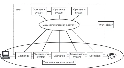
these resources are referred to as NEs. TMN enables communication between
operations systems(OSs) and NEs via adata communications network(DCN) as shown in Figure 4.6.
4.5.1 TMN Architecture
The architecture of TMN [10] is defined in terms of three perspectives: a physical architecture, a functional architecture, and an information architec-ture. Sections 4.5.1.1–4.5.1.3 examine these perspectives.
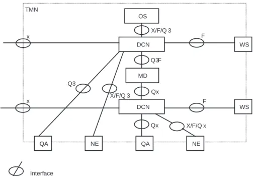
4.5.1.1 TMN Physical Architecture and Interfaces
The physical architecture, which is depicted in Figure 4.7, consists of the fol-lowing components:
• OS: The OS performs the management of NEs and services. It processes management information for monitoring, coordinating, and controlling telecommunications management functions. The OS can
Scenario #1 Scenario #2 Scenario #3 Scenario #4 OAM Cell OAM Cell OAM Cell OAM Cell OAM Cell Network #1 Network #2 Network #3 Virtual link Virtual connection
also provide some of the mediation, Q-adaptation, and WS functions. NMSs, andelement management systems(EMSs) are typical OSs. • NE: The NE consists of the network components that are being
man-aged. It contains manageable information that is monitored and con-trolled by an OS. To be managed within the scope of TMN, a NE must have a standard TMN interface. If a NE does not have a standard interface, it can still be managed via aQ-adapter (QA). The NE pro-vides the OS with a representation of its manageable information and functionality (i.e., the MIB). As a building block, an actual NE can also contain its own OS function, QA function, mediation device
(MD) function, etc.
• MD: The MD performs mediation between local TMN interfaces and the OS information model. A mediation function may be needed to ensure that the information, scope, and functionality are presented in the exact way that the OS expects. Mediation functions can be imple-mented across hierarchies of cascaded MDs.
• QA: The QA enables the TMN to manage NEs that do not have any TMN-compliant interfaces. The standard TMN interface is the
Operations system Operations system Operations system
Data communication network
Exchange Exchange Exchange Transmissionsystem Transmissionsystem
Work station
Telecommunication network TMN
Figure 4.6 TMN in relation to a telecommunications network. (Source: ITU-T Recommen-dations, M.3010 Figure 1.)
common management information service (CMIS)/(CMIP) as will be discussed later in this section. The QA translates between TMN and non-TMN interfaces. For instance, an SNMP QA translates between SNMP and CMIP.
• WS: The WS performs WS functions (i.e., translating information between a TMN format and a displayable format for the user).
It should be noted that one physical TMN block may represent more than one TMN functional block. For example, a switch with a built-in man-agement system also includes the OS function.
The information exchange between different TMN components are per-formed via standardized interfaces as listed below:
OS DCN MD DCN QA NE NE QA WS WS X/F/Q 3 F F X/F/Q 3 X/F/Q x Qx Qx Q3 x x TMN Q3F
DCN Data Communication Network MD Mediation Device
QA Q Adapter Interface
Figure 4.7 TMN components and interfaces. (Source: ITU-T Recommendations, M.3010 Figure II-1.)
• Q-Interface: The Q interface exists between two TMN-conformant functional blocks that are within the same TMN domain. The most important interface for TMN is the Q3 [11, 14], which supports all seven layers of the OSI reference model. Any functional component that interfaces directly to the OS uses the Q3 interface. In other words, the Q3 interface is between the NE and OS; QA and OS; MD and OS; and OS and OS.
The Qx is a simplified version of Q3, which is designed for use in environment-specific situations where it is not generally possible to support a Q3 interface. A Qx interface defines only the first three lay-ers of the OSI stack. The Qx carries information that is shared between the MD and the NEs that it supports. The Qx interface exists between the NE and MD; QA and MD; and MD and MD.
• X interface: The X interface exists between two TMN-conformant OSs in two separate domains, or between a TMN-conformant OS and another OS in a non-TMN network. This interface has not yet been fully standardized. However, it is likely to be very similar to Q3 but with more strict requirements on security.
• F interface: The F interface exists between a WS and OS and between a WS and MD. This interface has not yet been standardized.
The relationship of the TMN components and interfaces between them are depicted in Figure 4.7.
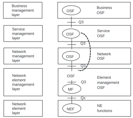
4.5.1.2 TMN Functional Architecture
The functional architecture of the TMN introduces layering of TMN manage-ment functionality as follows:
• Business management layer(BML): The BML deals with such functions as high-level planning, budgeting, goal setting, executive decisions, and business level agreements.
• Service management layer(SML): The SML uses information presented by the NML to manage contracted service to existing and potential customers. This is the basic point of contact with customers for provi-sioning, accounts, QoS, and fault management. The SML is also the key point for interaction with service providers and with other admin-istrative domains. It maintains statistical data to support QoS, etc. OSs
in the SML communicate with OSs in the SML of other administra-tive domains via the X interface. OSs in the SML interface with OSs in the BML via the Q3 interface.
• Network management layer (NML): The NML has visibility of the entire network, based on the NE information presented by the EML OSs. In other words, the NML has the firstmanaged viewof the net-work. The NML coordinates all network activities and supports the demands of the SML. OSs in the NML interface with OSs in the SML via the Q3 interface.
• Element management layer (EML): The EML manages each NE. The EML has element managers, or OSs, each of which are responsible for the TMN-manageable information in certain NEs. In general, an ele-ment manager is responsible for a subset of the NEs. An eleele-ment man-ager manages such areas as NE data, logs, and activity. Logically, MDs are in the EML, even when they are physically located in some other logical layer, such as the NML or SML. An MD communicates with an EML OS via the Q3 interface. In addition, an EML OS presents its management information from a subset of the NEs to an OS in the NML through the Q3 interface.
• NE layer (NEL): The NEL presents the TMN-manageable informa-tion in an individual NE. Both the NE and the Q-adapter, which adapts between TMN and non-TMN information, are located in this layer.
TMN management functions are categorized into functional blocks such as theNE function(NEF),operation system function (OSF),mediation function
(MF),WS function(WSF) anddata communication function(DCF). The same type of functions can be implemented at many levels, from the highest level, which manages a corporate or enterprise network, to a lower level that is defined by a network or network resource. Once management is defined at the lower layers, additional management applications can be built on this foundation.
A TMN physical building block contains one or more functional blocks that may communicate among themselves within the same building block or with function blocks in other building blocks. When function blocks in differ-ent building blocks communicate with one another, a TMN interface is used.
The key function in TMN is the OSF, which is responsible for such purposes as monitoring, coordinating, or controlling telecommunications
functions. The TMN OS functional hierarchy is illustrated in Figure 4.8. Note that in some instances it may be possible for administrations to bypass layers of communication within the functional hierarchy—in order to reduce the response time, for example.
4.5.1.3 TMN Information Architecture
The TMN information architecture is based on the existing OSI management framework. The core standards include the following.
• CMIP [15]: defines management services exchanged between peer entities;
• Guideline for definition of managed objects (GDMO) [16]: Provides templates for classifying and describing managed resources;
• ASN.1: Provides syntax rules for data types. Business management layer Service management layer Network management layer Network element management layer Network element layer OSF OSF OSF NEF OSF MF Q3 Q3 Q3 Q3 Qx NE functions Element management OSF Network OSF Service OSF Business OSF
Figure 4.8 Hierarchy of the OS function. (Source: ITU-T Recommendations, M.3010 Figure III-1.)
The key to the OSI management framework is the use of the object-oriented (OO) approach, with managed information in network resources modeled as attributes in managed object classes. The main properties of an object class include operations permitted, notifications emitted, attributes data contained, and behaviors executed.
Object-orientation is the technique that is generally considered to be superior in dealing with the complexity of network management tasks. The OO approach is typically characterized by features such as encapsulation, inheritance, object class, and allomorphs. Management information is encapsu-lated in managed objects, thereby hiding internal implementations from a user. The object class extends and combines object definitions to create multiple instances of an object class. Objects are organized into a tree-like structure via containment relationships. Object definitions can be extended by inheritance, which allows a new object class to be derived from an existing object class through extension, modification, or restriction, permitting the reuse of object definitions. In particular, a new object can acquire attributes, notifications, operations, and behavior from objects higher in the tree. Allomorphs allow an entity to take many forms, providing a mechanism for migration and coexis-tence between multiple versions of class and object definitions. Although man-aged resources in SNMP are referred to as objects, the information model in SNMP is not OO. This is because the model does not support the typical char-acteristics mentioned above. Please refer to [17] for further discussion.
4.5.2 TMN-Based ATM Management
TMN-based network management involves a generic information model that defines technology-independent TMN object classes [18] and an ATM-specific information model that defines ATM specific object classes. The management information is specified in terms of several different viewpoints as follows:
• NE View: Concerned with the information that is required to manage a NE including the information required to manage the NEF and the physical aspects of the NE;
• Network View: Concerned with the information representing the net-work, both physically and logically, including how NE entities are related, topographically interconnected, and configured to provide and maintain end-to-end connectivity;
• Service View: Concerned with how network view aspects (such as an end-to-end path) are utilized to provide a network service, including
the requirements of a network service (e.g. availability, and cost), how these requirements are met through the use of the network, and all related customer information.
ITU-T Recommendation I.751 [19] specifies the Q3 interface between an ATM cross-connect and the NMS. It provides management requirements and an information model that pertain to the plane management of the ATM NE. The information model describes the managed object classes and their properties that are used to describe the information exchanged across manage-ment interfaces defined in the ITU-T M.3010. The I.751 specializes the generic object classes that have already been defined in the TMN framework to provide the information model specific to the ATM NE.
The ATM Forum network management working group has also defined a set of standards for the management of ATM network based on TMN includ-ing the followinclud-ing:
• af-nm-0020.000: “M4 Interface Requirements and Logical MIB; ATM NE-view,” specifying the interface requirements and a logical MIB for the M4 network element view interface;
• af-nm-0027.000: “CMIP Specification for the M4 Interface,” specify-ing the Q3 protocol stack and CMIP MIB for the M4 network ele-ment view interface;
• af-nm-0071.000: “AAL Management for the M4 ‘NE View’ Inter-face,” specifying a set of requirements, logical information model, and CMIP specification to support AAL management;
• af-nm-0072.000: “CES Interworking M4 Interface ‘NE View’ Requirements, Logical and CMIP MIB,” specifying the requirements, protocol-independent managed entities, and CMIP MIB specification for circuit emulation service for the M4 network element view interface;
• af-nm-0058.000: “M4 Network-View Interface Requirements, and Logical MIB,” specifying the improvements to the M4 network-level protocol-independent MIB (AF-NM-0058.000);
• af-nm-0074.000: “ M4 Network View Requirements & Logical MIB Addendum,” specifying the interface requirements and a logical MIB for the M4 network view interface;
• af-nm-0073.000: “M4 Network View CMIP MIB Specification,” specifying the CMIP MIB for the M4 network element view interface;
ATM-Forum M4 and M5 interfaces are modeled as TMN interfaces. The M4 interface is a TMN Q3 interface between a public NMS and a TMN NE, an EMS, or another NMS. The M5 interface between two public NMSs of different network providers is a TMN X interface, i.e., an interface between OSs in different TMNs.
4.5.3 CMIP Versus SNMP
Both Internet SNMP and OSI CMIP provide an open, standard platform to perform interoperable network management in a multivendor, heterogeneous environment. They are very similar in terms of their functionality and basic approach.
CMIP and SNMP both use a client-server model in which the client is the managing system and the server is the managed system. The managed sys-tem (server) assumes an agent role, receiving management requests, executing commands, and transmitting unsolicited event notifications/traps. The manag-ing system (client), actmanag-ing in the role of a manager, invokes operations and receives notifications/traps. ASN.1 is used in both frameworks to describe man-agement information. However, there are some essential differences between the frameworks as described in Sections 4.5.3.1–4.5.3.5.
4.5.3.1 Information Model
The OSI management framework is based on the OO design principles in rep-resenting management information. The resources managed are presented in terms of managed objects and managed object classes. With OO concepts such as inheritance and allomorphs, management information can be organized in an orderly and structured manner, thus permitting a higher level of abstraction. This in turn allows the OSI information model to scale to large networks.
In contrast, MIB structure is relatively flat in SNMP. Management operations are restricted to scalar objects. The only constructed type supported is a simple two-dimensional conceptual table, consisting of only scalar objects. Thus it is difficult, if at all possible, to implement tables inside a table.
The object naming structure for SNMP is straightforward. Every object type has a registered OID, and an object instance is identified by the object type OID suffixed by a part that uniquely identifies that instance. By employ-ing such a scheme, however, no generic object can be defined. For example, a RowStatus object has to be defined for each table that permits row creation. Unlike SNMP, CMIP does not have such a restriction; this allows a generic RowStatus-like object to be used in any table.
Finally, although managed resources are also referred to as objects, SNMP is not OO. For example, an SNMP object cannot inherit from another object. OO was considered by early SNMP developers as creating unnecessary compli-cations without real benefits. SNMP objects are different from the objects that are defined in CMIP, in which the SNMP-equivalent managed information in network resources is modelled as the attributes of managed objects. CMIP noti-fications are defined as properties of the managed objects. In brief, the OSI information model is more flexible and powerful than that of SNMP.
4.5.3.2 Protocol
Both CMIP and SNMP are application layer protocols. CMIP is based on the well-known ISO-OSI reference model, which consists of seven layers. SNMP, on the other hand, conforms to the Internet four-layer protocol stack. The SNMP protocol stack is simpler than the OSI stack.
SNMP protocol messages are transferred over connectionless UDP. The prime motivation behind this choice is that SNMP must continue to operate (if at all possible) when the network is operating at its worst [20]. By using a con-nectionless transport protocol, SNMP takes on the responsibility of reliable data transmission. This means that an SNMP application may time out out-standing requests and either retransmit them or abort them as appropri-ate—this is normally done by a transport protocol. In contrast, CMIP makes use of a connection-oriented reliable service provided by the OSI transport layer. This service can be implemented over a variety of transport and network layer protocol combinations.
The protocol operations of SNMP have been deliberately specified to be very simple. SNMP-managed objects accept only Set and Get operations while imperative commands and table creation/deletion are emulated through Set. The CMIP provides a richer set of operations, including Get, Set, Action, Cre-ate, Delete, Event-report, and Cancel-get, permitting sophisticated access to managed objects. Imperative commands (e.g., Action, Create, and Delete) can be executed directly. Moreover, mechanisms such as scoping and filtering greatly reduce network management traffic. With scope, for example, CMIP can issue a single request to retrieve all the information needed, avoiding the problem of multiple requests that SNMP requires. By making use of filtering capabilities, threshold values in an agent can be set to eliminate the transmis-sion of routine information to a management station. In contrast, SNMP has no such mechanisms. As a result, SNMP requires a series of requests from the management station, transmitting normal as well as abnormal data. The
filtering of unwanted data is the responsibility of the network management sta-tion. It should be noted that scoping and filtering has a performance penalty on the agent, because of the complexity. Consequently, this mechanism has not been widely implemented. Despite the complicated mechanism used, the actual efficiency of moderately scoped/filtered CMIP protocol is not so high as expected as a result of the overhead of the protocol stack.
4.5.3.3 Management Philosophy
Both SNMP and CMIP accomplish the role of management in the overall dis-tributed architecture, albeit in different ways. The idea behind the ISO man-agement framework is distributing intelligence over a network (e.g., among managed and managing entities). The resulting solution is thus more flexible but requires more resources in terms of memory and processing capability in agents. Consequently, the entry cost for the first application is relatively expen-sive, but additional objects can be added at sometimes relatively smaller incre-mental costs.
In SNMP, the design strategy is to shift workload toward management stations so that the impact of adding network management to managed devices is minimal, reflecting a lowest common denominator. As a result, an SNMP agent can be implemented even in the smallest/cheapest of systems. Any required complexity is performed by an SNMP manager; hence, the opera-tional role and performance of a system is not compromised by the inclusion of an SNMP agent. Because the number of management stations is far less than that of management agents, overall system complexity and cost are optimized.
As the SNMP traps are sent asynchronously from managed devices to net-work management stations and are not retransmitted, they are inherently unre-liable. Accordingly, network mangers should not rely on them. Alternatively, most implementations use polling to check the status of agents. Although trap-directed polling is recommended, some implementations only use polling in order to reduce the complexity of management applications. This limits the scalability of SNMP to very large networks due to the amount of processing and traffic generated for polling managed devices.
The CMIP event reporting mechanism is very sophisticated, allowing for very flexible control of emitted notifications. CMIP-based network manage-ment adopts an event-driven mechanism as it employs a reliable OSI transport service and as agents are more intelligent. Event reports are generated to report important spontaneous events. Event reports also supply performance informa-tion. In this way, network overhead is considerably reduced, thus extending the
scalability of NMS. However, regular polling is necessary under all conditions to ensure the proper operation of a network.
4.5.3.4 Interoperability
The biggest strength of SNMP is its widespread popularity. SNMP-based net-work management has been accepted as the Internet standard management framework and has become deeply entrenched as the management framework of choice; it is now in pervasive and continuous use. Many MIB modules have been produced for a plethora of uses in network management, system manage-ment, application managemanage-ment, proxy management of legacy devices, and manager-to-manager communications. These MIBs reach virtually every kind of network technology. Now SNMP is taking over additional market segments while growing strong in the areas of telecommunications management, data and voice over cable, system management, and application management. As such, SNMP-based network management can be easily extended to applica-tions that run over the managed network.
The application of CMIP, on the other hand, is largely limited within the context of TMN. Though more and more CMIP MIBs have been specified to manage a number of telecommunications networks, their scope is limited mainly to new networking technologies, such as ATM and SONET.
4.5.3.5 Suitability for ATM Management
The OO approach and the scalability of the OSI network management frame-work are distinctive advantages in managing large netframe-works. Higher-level data is reflected automatically in the lower-level data because of inheritance and containment. For example, if an interface is down, all the protocols running over the interface are down. The scoping and filtering capability is especially useful when used in high-speed ATM networks, as a lot of alarm conditions may occur due to a link failure. This framework is made more attractive by the introduction of TMN with CMIP specified as the management protocol, as most carriers are committed to TMN.
However, the cost for the implementation of CMIP agents is much higher than that for SNMP, as the former is much more complex and requires many more resources than the former. As a result, the performance penalty on the agent (e.g., reduced throughput) may be significant. This effectively pre-vents CMIP from being used in other areas, such as data communications equipment. SNMP, on the other hand, offers a low entry cost, simplicity in implementation, and a fast standardization process.
Admittedly, SNMP is by no means perfect. SNMP was not designed to handle the huge volumes of network traffic that ATM generates. Some adapta-tion may be necessary for ATM management. For example, it may be necessary to use middle-level managers to correlate alarms generated by the switches in a large network to reduce management traffic. However, SNMP is well under-stood and widely used. A lot of SNMP MIBs have already been defined for ATM. These MIBs cover almost all aspects of ATM. Moreover, SNMP is well-balanced in terms of management functions and resources required, pro-viding a cost-effective and interoperable solution to the challenges of managing ATM networks. Most importantly, it is a proven technology. Almost all ATM switches today are SNMP-manageable. Similarly, most ATM applications are, or will be, running over TCP/IP that is managed by SNMP. As a result, the scope of SNMP-based ATM management can easily be extended to non-ATM devices and applications running over ATM. In addition, SNMP is evolving, and some of its deficiencies, such as security, have been overcome in newer ver-sions of the protocol. SNMP is an interoperable solution for ATM network management.
Taking into consideration the work that has been undertaken in the ATM Forum, CMIP and SNMP will coexist at least in the near future, although in different areas. SNMP will be used in access/private networks to allow existing NMSs and user applications to be integrated seamlessly, while CMIP will most likely be used in public telecommunications networks.
References
[1] ITU-T Recommendation X.700: “Management Framework for Open Systems Intercon-nection (OSI) for CCITT Applications,” 09/92.
[2] ITU-T Recommendation M.3400: “TMN management functions,” 10/92.
[3] Held, G.,Network Management, Techniques, Tools and Systems, New York, NY: John Wiley & Sons, 1992.
[4] ATM Forum, Customer Network Management (CNM) for ATM Public Network Service (M3 Specification), October 1994.
[5] Peter Alexander and Kacey Carpenter, “ATM Net Management: A Status Report,” Data Communications on the Web, September 1995, http://www.data.com/Tutori-als/ATM_Net_Management.html.
[6] ITU-T Recommendation X.160, “Architecture for Customer Network Management Serv-ice for Public Data Networks, 10/96.”
[7] ITU-T Recommendation X.161, “Definition of Customer Network Management Services for Public Data Networks,” 04/95.
[8] Holliman, G., M. Hinchliffe, N. Cook, and P. Barnes, “Customer Network Manage-ment,”Data Communications International,Vol. 24, No. 15, October 1995.
[9] ITU-T Recommendation I.610, “B-ISDN Operation and Maintenance Principles and Functions,” 03/93.
[10] ITU-T Recommendation M.3010, “Principles for a Telecommunications Management Network,” 10/92.
[11] ITU-T Recommendation Q.811: “Lower Layer Protocol Profiles for the Q3 Interface,” 03/93.
[12] ITU-T Recommendation Q.812: “Upper Layer Protocol Profiles for the Q3 Interface,” 03/93.
[13] ITU-T Recommendation Q.821: “Stage 2 and Stage 3 Description for the Q3 Inter-face—Alarm Surveillance,” 03/93.
[14] ITU-T Recommendation Q.822: “Stage 1, Stage 2 and Stage 3 Description for the Q3 Interface—Performance Management,” 04/94.
[15] CCITT Recommendation X.711, “Common Management Information Protocol (CMIP) Specification,” 1991.
[16] ITU-T Recommendation X.722, “Information Technology—Open Systems Interconnec-tion—Structure of Management Information: Guidelines for the Definition of Managed Objects,” 09/92.
[17] Rose, M. T.,The Simple Book: An Introduction to Internet Management,Second Edition, Englewood Cliffs, New Jersey: Prentice-Hall, 1994.
[18] ITU-T Recommendation M.3100, “Generic Network Information Model,” 10/92. [19] ITU-T Recommendation I.751: “Asynchronous Transfer Mode (ATM) Management of
the Network Element View,” 03/96.
[20] Kastenholz, F., Internet Engineering Task Force, RFC 1270, “SNMP Communications Services,” October 1991.