A Division of Microsoft Corporation One Microsoft Way
Redmond, Washington 98052-6399
Copyright © 2004 by Microsoft Corporation
All rights reserved. No part of the contents of this book may be reproduced or transmitted in any form or by any means without the written permission of the publisher.
Library of Congress Cataloging-in-Publication Data Corbin, Wendy,
1965-Designing a Microsoft Windows Server 2003 Directory and Network Infrastructure (70-297) / Wendy Corbin. p. cm.
Includes index. ISBN 0-07-225624-9
1. Electronic data processing personnel--Certification. 2. Microsoft
software--Examinations--Study guides. 3. Directory services (Computer network
technology)--Examinations--Study guides. 4. Microsoft Windows server. I. Hudson, Kurt. II. Title.
QA76.3.C668 2004
005.4'47682--dc22 2004045752
Printed and bound in the United States of America. 1 2 3 4 5 6 7 8 9 QWT 9 8 7 6 5 4 Distributed in Canada by H.B. Fenn and Company Ltd.
A CIP catalogue record for this book is available from the British Library.
Microsoft Press books are available through booksellers and distributors worldwide. For further information about interna tional editions, contact your local Microsoft Corporation office or contact Microsoft Press International directly at fax (425) 936-7329. Visit our Web site at www.microsoft.com/learning/. Send comments to mspinput@microsoft.com.
Active Directory, Microsoft, Microsoft Press, MS-DOS, Windows, and Windows Server are either registered trademarks or trademarks of Microsoft Corporation in the United States and/or other countries. Other product and company names men tioned herein may be the trademarks of their respective owners.
The example companies, organizations, products, domain names, e-mail addresses, logos, people, places, and events depicted herein are fictitious. No association with any real company, organization, product, domain name, e-mail address, logo, person, place, or event is intended or should be inferred.
This book expresses the author’s views and opinions. The information contained in this book is provided without any express, statutory, or implied warranties. Neither the authors, Microsoft Corporation, nor its resellers or distributors will be held liable for any damages caused or alleged to be caused either directly or indirectly by this book.
Acquisitions Editor: Linda Engelman Project Editor: John Pierce
Technical Editor: Beth Cohen Copyeditor: Ina Chang Indexer: Ginny Bess
SubAssy Part No. X10-63126 Body Part No. X10-53149
CHAPTER 1: Analyzing the Existing IT Infrastructure . . . 1
CHAPTER 2: Designing the DNS Structure . . . 43
CHAPTER 3: Designing a WINS Structure . . . 75
CHAPTER 4: Designing the Network and Routing Infrastructure . . . 101
CHAPTER 5: Designing the Forest and Domain Infrastructure . . . 129
CHAPTER 6: Planning Active Directory Sites and Server Placement . . . 161
CHAPTER 7: Designing an Administrative Security Structure . . . 191
CHAPTER 8: Designing and Securing Internet Connectivity . . . 231
CHAPTER 9: Designing a Strategy for Network Access. . . 263
APPENDIX A: Microsoft Solutions Framework Version 3.0 Overview . . . 305
APPENDIX B: Overview of Active Directory . . . 337
APPENDIX C: DNS Overview. . . 365
Glossary . . . 387
Index . . . 395
About This Book . . . xiii
CHAPTER 1: Analyzing the Existing IT Infrastructure . . . 1
Preparing for Design . . . 2
Project Planning . . . 2
Assembling a Design Team . . . 4
Documenting the Project . . . 6
Analyzing an Organization . . . 8
Geographical Analysis . . . 9
Recording Your Analysis . . . 14
Analyzing the Current WAN Connections . . . 15
Analyzing Information Flow. . . 16
Analyzing the Current Administration Model . . . 17
Analyzing the Existing Network Topology . . . 19
Routers and Other Networking Equipment. . . 19
IP Addressing . . . 21
Documenting the Servers and Workstations. . . 23
Analyzing Performance Requirements . . . 26
Analyzing the Existing Directory Structure . . . 29
Current Domain Model. . . 30
Analyzing the Current OU Structure. . . 31
Analyzing Active Directory Domain Controller Placement . . . 32
Analyzing an Existing Windows NT 4.0 Infrastructure . . . 33
Windows Server 2003 Functional Levels . . . 35
Summary . . . 37
Review Questions . . . 38
Case Scenarios . . . 39
CHAPTER 2: Designing the DNS Structure . . . 43
Analyzing the Existing DNS Implementation . . . 44
DNS Overview . . . 44
Components of DNS . . . 45
Designing a DNS Name Resolution Strategy . . . 51
Creating the Namespace Design. . . 52
Interoperability with Active Directory, DHCP, and WINS. . . 54
Zone Requirements . . . 58
Security . . . 58
Interoperability with UNIX Berkeley Internet Name Domain (BIND) . . . 62
Designing DNS Server Placement . . . 64 Server Placement . . . 65 Monitoring DNS Performance . . . 66 Load Balancing. . . 67 Summary . . . 68 Review Questions . . . 68 Case Scenarios . . . 70
Scenario 2-1: DNS Design for Northwind Traders . . . 70
Scenario 2-2: Planning DNS for Adventure Works . . . 71
CHAPTER 3: Designing a WINS Structure . . . 75
Gathering Information . . . 76
Understanding WINS . . . 77
NetBIOS Name Resolution . . . 77
Determining the NetBIOS Resolution Method . . . 80
WINS Components . . . 82
The WINS Database. . . 86
Database Size . . . 87
Designing a WINS Infrastructure . . . 87
Creating the Conceptual Design . . . 88
Determining the Number of WINS Servers . . . 89
Designing a WINS Server Placement Strategy . . . 89
Designing a WINS Replication Strategy. . . 91
Creating a Replication Strategy . . . 91
Deleting and Tombstoning Records . . . 95
Securing Your WINS Infrastructure . . . 95
Summary . . . 96
Review Questions . . . 97
Case Scenarios . . . 98
Scenario 3-1: Designing a WINS Replication Strategy . . . 98
Scenario 3-2: Analyzing a WINS Infrastructure . . . 99
CHAPTER 4: Designing the Network and Routing Infrastructure . . . 101
Design Team Roles . . . 102
Design Tasks . . . 103
Design Plans. . . 104
Comparing the Existing Network Infrastructure with the Plans . . . 106
IP Addressing Design . . . 107
IP Address Classes . . . 107
Subnetting a Network. . . 110
Supernetting and Classless InterDomain Routing (CIDR) . . . 114
Designing a DHCP Infrastructure . . . 116
DHCP Server Placement . . . 117
DHCP Server Redundancy . . . 119
Other Design Considerations . . . 123
Summary . . . 124
Review Questions . . . 125
Case Scenarios . . . 126
Scenario 4-1: Designing IP Addressing for Coho Winery . . . 126
Scenario 4-2: Designing DHCP for Northwind Traders . . . 126
CHAPTER 5: Designing the Forest and Domain Infrastructure . . . 129
Design Team Roles and Design Tasks. . . 130
Design Components . . . 130
Determining Business Requirements and Priorities . . . 131
Determining the Forest Design. . . 132
Documenting the Forest Plan . . . 135
Determining the Domain Design . . . 135
Single-Domain Model. . . 136
Multiple-Domain Model. . . 137
Determining the Forest Root Domain . . . 141
Single-Domain Model. . . 141
Multiple-Domain Model. . . 141
Documenting the Domain Plan. . . 143
Determining the DNS Namespace Design . . . 144
Selecting a Domain Name . . . 145
Documenting the DNS Namespace Design . . . 146
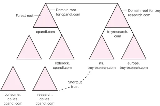
Determining a Trust Strategy . . . 147
Overview of Trusts . . . 147
Forest Trusts . . . 148
Shortcut Trusts . . . 149
External Trusts. . . 150
Realm Trusts . . . 151
Trust Strategy Design Guidelines. . . 151
Documenting the Trust Strategy . . . 152
Determining a Migration Plan . . . 152
Migration Strategies . . . 153
Documenting the Migration Strategy . . . 154
Summary . . . 156
Review Questions . . . 157
Case Scenario. . . 157
Scenario 5-1: Determining the Northwind Traders Forest and Domain Design . . . 157
CHAPTER 6: Planning Active Directory Sites and
Server Placement . . . 161
Design Tasks. . . 162
Understanding Sites . . . 163
Controlling Workstation Logon Traffic . . . 164
Controlling Replication Traffic . . . 165
Controlling a DFS Topology . . . 165
Controlling the FRS . . . 166
Designing Site Boundaries. . . 166
Designing a Replication Strategy . . . 168
The Replication Process . . . 168
Site Links . . . 170
Planning a Domain Controller Strategy. . . 176
Determining Domain Controller Capacity . . . 176
Determining Whether a Location Needs a Domain Controller . . 178
Determining the Number of Required Domain Controllers . . . . 179
Placing Forest Root Domain Controllers . . . 179
Planning for Global Catalog Servers . . . 180
Planning for Operations Master Servers . . . 181
Documenting the Design. . . 184
Summary . . . 185
Review Questions . . . 186
Case Scenarios . . . 187
Scenario 6.1: Creating a Site Design and Replication Strategy for Northwind Traders. . . 187
Scenario 6.2: Graphic Design Institute Plan. . . 189
CHAPTER 7: Designing an Administrative Security Structure . . . 191
Gathering and Analyzing Design Information. . . 192
Choosing an Administration Model . . . 193
Understanding Organizational Units . . . 194
Standard Models for OU Structure . . . 195
Using OUs to Delegate Administrative Control . . . 200
Envisioning the OU Structure. . . 202
Planning for Inheritance . . . 203
Using OUs to Limit Object Visibility . . . 204
Organizational Units and Group Policy . . . 205
Determining Design Requirements. . . 205
Group Policy Design Considerations . . . 209
Planning an Account Strategy. . . 219
Types of Accounts . . . 219
Account Naming Strategies . . . 220
Planning a Password Policy . . . 221
Creating an Authentication, Authorization, and Administration Strategy . . . 222
Designing a Security Group Strategy . . . 223
Summary . . . 225
Review Questions . . . 226
Case Scenarios . . . 227
Scenario 7-1: Planning an Administrative Structure. . . 227
Scenario 7-2: Planning an Account Strategy . . . 229
CHAPTER 8: Designing and Securing Internet Connectivity . . . 231
Gathering and Analyzing Information. . . 232
Overview of Connection Types . . . 233
Determining Connection Types . . . 236
Designing an Internal and External Connectivity Plan . . . 238
Understanding Three-Tier Internetwork Routing . . . 239
Developing the Intersite Connectivity Design. . . 241
Designing a VPN . . . 242
Designing Internet Connectivity . . . 244
Protecting Your Private Network. . . 244
Firewalls and Replication . . . 247
Promoting Domain Controllers Through a Firewall . . . 249
Designing NAT . . . 249
Limitations of NAT . . . 252
Creating the Conceptual Design . . . 253
NAT Servers . . . 255
Securing Your NAT Solution . . . 256
Summary . . . 258
Review Questions . . . 259
Case Scenarios . . . 260
Scenario 8-1: Designing a Connectivity Solution . . . 260
Scenario 8-2: Implementing NAT . . . 261
CHAPTER 9: Designing a Strategy for Network Access. . . 263
Gathering and Analyzing Information. . . 264
Remote Access Connection Methods . . . 266
Dial-up Networking. . . 266
Authentication Methods . . . 269
Selecting an Authentication Protocol. . . 272
Encryption Methods . . . 273
Integrating NAT with VPN . . . 274
Authentication Using Remote Access Server . . . 274
Using an Internet Authentication Service Server . . . 276
How RADIUS Works. . . 276
Designing a RADIUS Solution . . . 278
Placing Remote Access Servers . . . 280
RAS Servers . . . 281
VPN Servers . . . 283
RADIUS Servers . . . 286
Designing a Remote Access Policy . . . 287
Remote Access Policy Profile . . . 289
Hardware Requirements. . . 291
Communication Links . . . 292
Service Providers . . . 292
Client Hardware . . . 292
Redundancy . . . 292
Wireless Network Access . . . 293
Wireless Access Points. . . 293
Access Method . . . 295
Security Strategies . . . 298
Rogue Access Points . . . 299
Managing Wireless Access . . . 299
Summary . . . 300
Review Questions . . . 301
Case Scenarios . . . 302
Scenario 9.1: Designing a Remote Access Strategy . . . 302
Scenario 9.2: Designing Wireless Network Access . . . 304
APPENDIX A: Microsoft Solutions Framework Version 3.0 Overview . . . 305
Abstract . . . 306
Audience . . . 306
Introduction . . . 306
MSF Origins and Brief History. . . 307
Challenges and Opportunities. . . 307
A Solution Based on Experience . . . 309
MSF and Microsoft Operations Framework . . . 309
Key MSF Terms. . . 310
Foster Open Communications . . . 312
Work Toward a Shared Vision . . . 313
Empower Team Members. . . 314
Establish Clear Accountability and Shared Responsibility . . . 316
Focus on Delivering Business Value . . . 317
Stay Agile, Expect Change . . . 318
Invest in Quality . . . 319
Learn From All Experiences . . . 320
MSF Models . . . 321
The MSF Team Model . . . 322
The MSF Process Model . . . 323
MSF Disciplines . . . 325
The MSF Project Management Discipline . . . 325
The MSF Risk Management Discipline . . . 327
The MSF Readiness Management Discipline . . . 328
Microsoft’s Use of MSF . . . 329
MSF in Microsoft Product Groups and Services . . . 330
MSF Elsewhere in Microsoft . . . 330
Implementing MSF . . . 331
Learning MSF . . . 331
Using MSF . . . 332
Summary . . . 332
Addendum: MSF, Industry Standards, and Methodologies . . . 333
MSF and the Software Engineering Institute (SEI) Capability Maturity Model Integration (CMMI). . . 333
MSF and Agile Software Development Methodologies . . . 334
MSF and Project Management Bodies of Knowledge . . . 335
MSF and the International Organization for Standardization (ISO) . . . 335
APPENDIX B: Overview of Active Directory . . . 337
Active Directory’s Functions and Benefits . . . 337
Centralized Resource and Security Administration . . . 338
Single Point of Access to Resources . . . 339
Fault Tolerance and Redundancy . . . 339
Simplified Resource Location. . . 340
Active Directory Schema . . . 341
Active Directory Components. . . 343
Organizational Units . . . 344
Domains . . . 345
Trees . . . 346
Sites . . . 348
Naming Standards . . . 349
Planning an Active Directory Implementation . . . 351
The Logical and Physical Structure . . . 351
The Role of DNS. . . 352
Windows Server 2003 Forest and Domain Functional Levels . . . . 353
Understanding and Comparing Active Directory Trust Models . . 361
Summary . . . 364
APPENDIX C: DNS Overview. . . 365
Name Resolution. . . 365
What Is Name Resolution? . . . 365
What Is a Host Name? . . . 366
Resolving Host Names . . . 366
The Domain Name System (DNS). . . 368
What Is a Domain? . . . 369
Understanding Domain Hierarchy Levels . . . 371
Understanding the DNS Name Resolution Process . . . 373
Using Active Directory . . . 376
Combining Internal and External Domains . . . 376
Creating an Internal Root . . . 377
Understanding DNS Server Types . . . 378
Creating Zones . . . 380
Glossary . . . 387
Welcome to Designing a Microsoft Windows Server 2003 Active Directory and Network Infrastructure (70-297), part of the Microsoft Official Academic Course (MOAC) series. Through lectures, discussions, demonstrations, review questions, and classroom labs, this course teaches you the skills and knowledge necessary to design an Active Directory and network infrastructure that meets the technical and business requirements of an organization. Understanding the design pro cess, required components, and the integration of technologies are key elements in designing a successful network infrastructure. This book also helps prepare you to take the Microsoft 70-297 exam. Successful completion of the 70-297 exam will fulfill the design credit within the MCSE certification core. The 70-297 exam is one of the available design exams in the Microsoft Certified Systems Engineer (MCSE) certification track.
TARGET AUDIENCE
This course provides comprehensive coverage of the skills necessary for people aspiring to obtain positions such as systems engineer, systems analyst, or high-level systems administrator on Microsoft Windows Server 2003 networks. It is also intended to meet the needs of individuals preparing for the MCSE Windows Server 2003 certification.
PREREQUISITES
The prerequisite for this course is the completion of the courses titled Planning and Maintaining a Windows Server 2003 Network Infrastructure (70-293) and Planning, Implementing, and Maintaining a Windows Server 2003 Active Directory Infrastructure (70-294) or knowledge equivalent to the skills presented in these courses. You should also have any prerequisite knowledge or have completed prerequisite course work defined by the learning institution and instructor.
THE TEXTBOOK
The textbook content has been crafted to provide a meaningful learning experi ence to students in an academic classroom setting.
Key features of the Microsoft Official Academic Course textbooks include the following:
■ Learning objectives for each chapter that prepare the student for the
topic areas covered in that chapter.
■ Chapter introductions that explain why the content is important. ■ An inviting design with screen shots, diagrams, tables, lists, and other
graphical formats that makes the book easy to comprehend and sup-ports a number of different learning styles.
■ Clear explanations of concepts and principles.
■ A variety of reader aids that highlight a wealth of additional informa tion, including:
❑ Note – Real-world application tips and alternative procedures, and explanations of complex procedures and concepts
❑ Caution – Warnings about mistakes that can result in loss of data or are difficult to resolve
❑ Important – Explanations of essential setup steps before a procedure and other instructions
❑ More Info – Cross-references and additional resources for students
■ End-of-chapter review questions that assess knowledge and can serve as homework, quizzes, and review activities before or after lectures. (Answers to the textbook questions are available from your instructor.)
■ Chapter summaries that distill the main ideas in a chapter and
rein-force learning.
■ Case scenarios, approximately two per chapter, that provide students with an opportunity to evaluate, analyze, synthesize, and apply infor mation learned during the chapter.
■ A comprehensive glossary that defines key terms introduced in the book.
THE SUPPLEMENTAL COURSE MATERIALS CD-ROM
This book comes with a Supplemental Course Materials CD-ROM, which con tains a variety of informational aids to complement the book content:■ An electronic version of this textbook (eBook). For information about using the eBook, see the section titled “eBook Setup Instructions” later in this introduction.
■ The Microsoft Press Readiness Review Suite built by MeasureUp. This suite of practice tests and objective reviews contains questions of vary ing complexity and offers multiple testing modes. You can assess your understanding of the concepts presented in this book and use the results to develop a learning plan that meets your needs.
■ Job aids from the Windows Server 2003 Deployment Kit. (The docu
ments are stored in the folder named Textbook\Job Aids.) Job aids are worksheets and resources that can be used as the basis of a deploy ment plan for Windows Server 2003. They are designed to be used in conjunction with the Windows Server 2003 Deployment Kit.
■ Files used to complete the exercises in the lab manual. These files are located in the folder named Lab Manual.
■ An eBook of the Microsoft Encyclopedia of Networking, Second Edition.
■ Microsoft PowerPoint slides based on textbook chapters, for note-taking. ■ Microsoft Word Viewer and Microsoft PowerPoint Viewer.
A second CD contains a 180-day evaluation edition of Windows Server 2003, Enterprise Edition.
NOTE The 180-day evaluation edition of Windows Server 2003, Enter prise Edition that is provided with this book is not the full retail product; it is provided only for the purposes of training and evaluation. Microsoft Technical Support does not support this evaluation edition.
Readiness Review Suite Setup Instructions
The Readiness Review Suite includes a practice test of 300 sample exam ques tions and an objective review with an additional 125 questions. Use these tools to reinforce your learning and to identify areas in which you need to gain more expe rience before taking the exam.
� Installing the Practice Test
1. Insert the Supplemental Course Materials CD into your CD-ROM drive.
NOTE If AutoRun is disabled on your machine, refer to the Readme.txt file on the Supplemental Course Materials CD.
2. On the user interface menu, select Readiness Review Suite and follow the prompts.
eBook Setup Instructions
The eBook is in Portable Document Format (PDF) and must be viewed using Adobe Acrobat Reader.
� Using the eBook
1. Insert the Supplemental Course Materials CD into your CD-ROM drive.
NOTE If AutoRun is disabled on your machine, refer to the Readme.txt file on the CD.
2. On the user interface menu, select Textbook eBook and follow the prompts. You also can review any of the other eBooks provided for your use.
NOTE You must have the Supplemental Course Materials CD in your CD-ROM drive to run the eBook.
THE LAB MANUAL
The Lab Manual is designed for use in either a combined or separate lecture and lab. The exercises in the Lab Manual correspond to textbook chapters and are intended for use in a classroom setting under the supervision of an instructor. The Lab Manual presents a rich, hands-on learning experience that encourages practical solutions and strengthens critical problem-solving skills:
■ Lab exercises teach procedures by using a step-by-step format. Ques tions interspersed throughout the lab exercises encourage reflection and critical thinking about the lab activity.
■ Lab review questions appear at the end of each lab and ask questions about the lab. They are designed to promote critical reflection.
■ Lab challenges are review activities that ask students to perform a vari ation on a task they performed in the lab exercises but without detailed instructions.
■ Review labs appear after a number of regular labs and consist of mid-length review projects based on true-to-life scenarios. These labs chal lenge students to “think like an expert” to solve complex problems.
■ Labs are based on realistic business settings and include an opening scenario and a list of learning objectives.
Students who successfully complete the lab exercises, lab review questions, lab challenges, and review labs in the Lab Manual will have a richer learning experi ence and deeper understanding of the concepts and methods covered in the course. They will be better able to answer and understand the testbank questions, especially the knowledge application and knowledge synthesis questions. They will also be much better prepared to pass the associated certification exams if they choose to take them.
NOTATIONAL CONVENTIONS
The following conventions are used throughout this texbook and the Lab Manual:
■ Characters or commands that you type appear in bold type.
■ Terms that appear in the glossary also appear in bold type.
■ Italic in syntax statements indicates placeholders for variable informa tion. Italic is also used for book titles and terms defined in the text.
■ Names of files and folders are capitalized, except when you are to type them directly. Unless otherwise indicated, you can use all lowercase letters when you type a filename in a dialog box or at a command prompt.
■ Filename extensions appear in all lowercase.
■ Acronyms appear in all uppercase.
■ Monospace type is used for code samples, examples of user interface text, or entries that you might type at a command prompt or in initial ization files.
■ Square brackets [ ] are used in syntax statements to enclose optional
items. For example, [filename] in command syntax indicates that you can type a filename with the command. Type only the information within the brackets, not the brackets themselves.
■ Braces { } are used in syntax statements to enclose required items. Type only the information within the braces, not the braces themselves.
KEYBOARD CONVENTIONS
■ A plus sign (+) between two key names means that you must press those keys at the same time. For example, “Press ALT+TAB” means that you hold down ALT while you press TAB.
■ A comma (,) between two or more key names means that you must press the keys consecutively, not at the same time. For example, “Press ALT, F, X” means that you press and release each key in sequence. “Press ALT+W, L” means that you first press ALT and W at the same time, and then you release them and press L.
COVERAGE OF EXAM OBJECTIVES
This book is intended to support a course that is structured around concepts and practical knowledge fundamental to this topic area, as well as the tasks that are cov ered in the objectives for the MCSE 70-297 exam. The following table correlates the exam objectives with the textbook chapters and Lab Manual lab exercises. You may also find this table useful if you decide to take the certification exam.
NOTE The Microsoft Learning Web site describes the various MCP certi-fication exams and their corresponding courses. It provides up-to-date certification information and explains the certification process and the course options. See http://www.microsoft.com/traincert/ for up-to-date information about MCP exam credentials about other certification pro-grams offered by Microsoft.
Textbook and Lab Manual Coverage of Exam Objectives for MCSE Exam 70-297
Objective Textbook Lab Manual
Creating the Conceptual Design by Gathering and Analyzing Business and Technical Requirements
Analyze hardware and software Chapter 1 Lab 1 requirements
Analyze interoperability requirements Chapter 1 Lab 1 Analyze the current level of service All chapters Labs 2, 3, 4, within an existing technical environment 8, and 9 Analyze the current network Chapter 1 Lab 2 administration model
Analyze network requirements All chapters All labs Analyze the current DNS infrastructure Chapter 1 Lab 2 Analyze the current namespace Chapter 1 Lab 2 Identify the existing domain model Chapter 1 Lab 1 Identify the number and location of Chapter 1 Lab 1 domain controllers on the network
Textbook and Lab Manual Coverage of Exam Objectives for MCSE Exam 70-297
Objective Textbook Lab Manual
Identify the configuration details of all servers Chapter 1 Lab 1 on the network. Server types might include
primary domain controllers, backup domain controllers, file servers, print servers, and Web servers
Analyze current security policies, Chapter 1 All labs standards, and procedures
Identify the impact of Active Directory Chapter 1 Lab 7 on the current security infrastructure
Identify the existing trust relationships Chapter 1 Lab 1 Design the envisioned administration Chapter 7
model
Create the conceptual design of the Active Chapter 5 Lab 5 Directory forest structure
Create the conceptual design of the Active Chapter 5 Lab 5 Directory domain structure
Design the Active Directory replication Chapter 6 Lab 6 strategy
Create the conceptual design of the Chapter 7 Lab 7 organizational unit (OU) structure
Create the conceptual design of the DNS Chapter 2 Lab 2 infrastructure
Create the conceptual design of the WINS Chapter 3 Lab 3 infrastructure
Create the conceptual design of the DHCP Chapter 4 Lab 4 infrastructure
Create the conceptual design of the remote Chapter 9 Lab 9 access infrastructure
Identify constraints in the current network Chapter 1 Lab 1 infrastructure
Interpret current baseline performance Chapter 1 Lab 1 requirements for each major subsystem
Creating the Logical Design for an Active Directory Infrastructure
Identify the Group Policy requirements for Chapter 7 Lab 7 the OU structure
Textbook and Lab Manual Coverage of Exam Objectives for MCSE Exam 70-297
Objective Textbook Lab Manual
Design an OU structure for the purpose Chapter 7 Lab 7 of delegating authority
Define the scope of a security group to meet Chapter 7 Lab 7 requirements
Select authentication mechanisms Chapters 7, 8, Labs 7, 8,
and 9 and 9
Optimize authentication by using Chapter 7 shortcut trust relationships
Specify account policy requirements Chapter 7 Lab 7 Specify account requirements for users, com- Chapter 7 Lab 7 puters, administrators, and services
Identify Internet domain name registration Chapter 5 Lab 5 requirements
Specify the use of a hierarchical namespace Chapter 5 Lab 5 within Active Directory
Identify NetBIOS naming requirements Chapter 3 Lab 3 Define whether the migration will include Chapter 5 Lab 5 an in-place upgrade, domain restructuring,
or migration to a new Active Directory environment
Design the administration of Group Policy Chapter 7 Lab 7 Objects (GPOs)
Design the deployment strategy of GPOs Chapter 7 Lab 7 Create a strategy for configuring the user Chapter 7 Lab 7 environment with Group Policy
Create a strategy for configuring the computer Chapter 7 Lab 7 environment with Group Policy
Design sites Chapter 6 Lab 6
Identify site links Chapter 6 Lab 6
Creating the Logical Design for a Network Services Infrastructure
Create the namespace design Chapter 2 Lab 2 Identify DNS interoperability with Active
Directory, WINS, and DHCP
Chapter 2 Labs 2, 3, and 4
Specify zone requirements Chapter 2 Lab 2
Textbook and Lab Manual Coverage of Exam Objectives for MCSE Exam 70-297
Objective Textbook Lab Manual
Design a DNS strategy for interoperability Chapter 2 Lab 2 with UNIX Berkeley Internet Name Domain
(BIND) to support Active Directory
Design a WINS replication strategy Chapter 3 Lab 3 Identify security host requirements Chapter 9 Labs 8 and 9 Identify the authentication and accounting Chapter 9 Labs 8 and 9 provider
Design remote access policies Chapter 9 Lab 9 Specify logging and auditing settings Chapter 9 Lab 9 Design a strategy for DNS zone storage Chapter 2 Lab 2 Specify the use of DNS server options Chapter 2 Lab 2 Identify the registration requirements Chapter 2 Lab 2 of specific DNS records
Specify the remote access method Chapter 9 Lab 9 Specify the authentication method for remote Chapter 9 Lab 9 access
Specify DHCP integration with DNS Chapter 4 Lab 4 infrastructure
Specify DHCP interoperability with client Chapter 4 Lab 4 types
Creating the Physical Design for an Active Directory and Network Infrastructure
Design DNS service placement Chapter 2 Lab 2 Design the placement of domain controllers Chapter 6 Lab 6 and global catalog servers
Plan the placement of flexible operations Chapter 6 Lab 6 master roles
Select the domain controller creation Chapter 6 Lab 6 process
Specify the server specifications to Chapters 8 Labs 8 and 9
meet system requirements and 9
Design Internet connectivity for a company
Chapters 8 and 9
Labs 8 and 9 Design a TCP/IP addressing scheme
through the use of IP subnets
Chapter 4 Lab 4 Specify the placement of routers Chapter 4 Lab 4
Textbook and Lab Manual Coverage of Exam Objectives for MCSE Exam 70-297
Objective Textbook Lab Manual
Design an IP address assignment by using Chapter 4 Lab 4 DHCP
Design a perimeter network Chapters 8 Labs 8 and 9 and 9
Plan capacity Chapter 9
Ascertain network settings required Chapter 9 Lab 9 to access resources
Design for availability, redundancy, Chapter 9 Labs 2, 4, 5,
and survivability 8, and 9
THE MICROSOFT CERTIFIED PROFESSIONAL PROGRAM
The MCP program is one way to prove your proficiency with current Microsoft products and technologies. These exams and corresponding certifications are developed to validate your mastery of critical competencies as you design and develop, or implement and support, solutions using Microsoft products and tech nologies. Computer professionals who become Microsoft certified are recognized as experts and are sought after industry-wide. Certification brings a variety of benefits to the individual and to employers and organizations.MORE INFO For a full list of MCP benefits, go to http:// www.microsoft.com/learning/itpro/default.asp.
Certifications
The MCP program offers multiple certifications, based on specific areas of techni cal expertise:
■ Microsoft Certified Professional (MCP) In-depth knowledge of at least one Windows operating system or architecturally significant plat-form. An MCP is qualified to implement a Microsoft product or tech nology as part of a business solution for an organization.
■ Microsoft Certified Systems Engineer (MCSE) Qualified to effec tively analyze the business requirements for business solutions and design and implement the infrastructure based on the Windows and Windows Server 2003 operating systems.
■ Microsoft Certified Systems Administrator (MCSA) Qualified to manage and troubleshoot existing network and system environments based on the Windows and Windows Server 2003 operating systems.
■ Microsoft Certified Database Administrator (MCDBA) Qualified to design, implement, and administer Microsoft SQL Server databases.
■ Microsoft Certified Desktop Support Technician (MCDST) Qualified to support end users and to troubleshoot desktop environments on the Microsoft Windows operating system.
MCP Requirements
Requirements differ for each certification and are specific to the products and job functions addressed by the certification. To become an MCP, you must pass rigor ous certification exams that provide a valid and reliable measure of technical proficiency and expertise. These exams are designed to test your expertise and ability to perform a role or task with a product, and they are developed with the input of industry professionals. Exam questions reflect how Microsoft products are used in actual organizations, giving them real-world relevance.
■ Microsoft Certified Professional (MCP) candidates are required to pass
one current Microsoft certification exam. Candidates can pass addi tional Microsoft certification exams to validate their skills with other Microsoft products, development tools, or desktop applications.
■ Microsoft Certified Systems Engineer (MCSE) candidates are required
to pass five core exams and two elective exams.
■ Microsoft Certified Systems Administrator (MCSA) candidates are
required to pass three core exams and one elective exam.
■ Microsoft Certified Database Administrator (MCDBA) candidates are
required to pass three core exams and one elective exam.
■ Microsoft Certified Desktop Support Technician (MCDST) candidates are required to pass two core exams.
ABOUT THE AUTHORS
The textbook, Lab Manual, pretest, testbank, and PowerPoint slides were written by instructors and developed exclusively for an instructor-led class-room environment.
Wendy Corbin, the author of the textbook, has 12 years of technology teaching experience that includes corporate, private, and academic instruction. Ms. Corbin began her career in technology as an end-user applications trainer and Certified Novell Instructor for a national computer training company. After adding MCSE courses to her instructional skill set, she moved on to work for a systems
integrator as a network engineer and technical consultant. Currently, Wendy is the Department Chair for Computer Networking at Baker College in Auburn Hills, Michigan. In addition, she works as an independent network engineer whenever possible. This work enables her to bring real-world skills and scenarios to the classroom by sharing her field experiences. Ms. Corbin holds a Bachelor of Arts degree from Oakland University in Rochester, Michigan, and is pursuing a Masters of Science degree in Information Technology with a concentration in Network Architecture and Design from Capella University. Her technical certifi cations include Microsoft MCT, MCSE, MCP + I; Novell CNI, CNE; and Cisco CCNA, CCAI.
Wendy is indebted to her coauthor, Kurt Hudson, for his work and effort, as well as for the sound advice and support he provided throughout the duration of this project. Wendy lives in Sterling Heights, Michigan, with her husband, Gary, and their two wonderful children, Joshua and Allegra. Their unconditional love, sup-port, and encouragement are appreciated more than they will ever know. Kurt Hudson, the author of the Lab Manual, pretest, testbank questions, and PowerPoint slides, is an instructor, author, and consultant for computer technol ogies. Kurt has written and contributed to numerous computer-related publica tions. In recent years, he has concentrated on the areas of computer networking, Active Directory, integrating UNIX and Microsoft Windows, and computer secu rity. Kurt regularly teaches summer programs at Northern Arizona University in Flagstaff, Arizona. He also has taught courses through Microsoft Research for several other universities throughout the United States.
Kurt completed a Masters of Management (MSM) with Troy State University in Troy, Alabama, in 1994. Kurt has been an MCT and MCSE since 1996 and has continued to upgrade his certifications with each new version of Windows since Windows NT 3.51 (now at Windows Server 2003 MCSE). He is also a Windows Server MVP in Directory Services and has several other technical certifications from Microsoft and CompTIA.
Kurt appreciates the hard work and dedication of Wendy Corbin. He is also grate ful for the assistance of Derek Melber, Diana Huggins, and Terry Bright with this publication. Kurt is also blessed to have a wonderful and supportive wife, Laura. Both Kurt and Wendy would like to extend their gratitude to Walter Glenn and Michael T. Simpson, authors of the MCSE Exam 70-297 Self-Paced Training Kit, and our technical editors, Beth Cohen and Robert Lyon. In addition, the incredi ble support given by the Microsoft Press team including Linda Engelman, John Pierce, and Lynn Finnel is appreciated more than words can express.
FOR MICROSOFT OFFICIAL ACADEMIC
COURSE SUPPORT
Every effort has been made to ensure the accuracy of the material in this book and the contents of the CD-ROM. Microsoft Learning provides corrections for books through the World Wide Web at the following address:
http://www.microsoft.com/learning/support/
If you have comments, questions, or ideas regarding this book or the companion CD-ROM, please send them to Microsoft Press using either of the following methods:
Postal Mail: Microsoft Press
Attn: Designing a Microsoft Windows Server 2003 Active Directory and Network Infra structure (70-297) Editor
One Microsoft Way
Redmond, WA 98052-6399 E-mail: moac@microsoft.com
Please note that product support is not offered through the above addresses.
EVALUATION EDITION SOFTWARE SUPPORT
The 180-day evaluation edition of Windows Server 2003, Enterprise Edition pro vided with this textbook is not the full retail product and is provided only for training and evaluation purposes. Microsoft and Microsoft Technical Support do not support this evaluation edition. They differ from the retail version only in that Microsoft and Microsoft Technical Support do not support them, and they expire after 180 days. For information about issues relating to the use of these evaluation editions, go to the Support section of the Microsoft Learning Web site (http://www.microsoft.com/learning/support/).
For online support information relating to the full version of Windows Server 2003, Enterprise Edition that might also apply to the evaluation edition, go to http://support.microsoft.com. For information about ordering the full version of any Microsoft software, call Microsoft Sales at (800) 426-9400 or visit http://www.microsoft.com.
ANALYZING THE EXISTING IT
INFRASTRUCTURE
Upon completion of this chapter, you will be able to:
■ Implement the steps required to prepare for a design project. ■ Explain the phases of the System Development Life Cycle. ■ List and define each of the roles of the design team.
■ Prepare and explain the documents that should be created as part of the design project.
■ List and explain the documents necessary to analyze an existing organiza tion’s structure.
■ Differentiate between geographical models.
■ List and explain the documents necessary to analyze an existing network topology.
■ List and explain the documents necessary to analyze the structure of an existing Windows 2000 or Windows NT 4.0 domain.
■ Use the analysis to assist in making initial decisions about the conceptual structure of an organization’s network based on business requirements and technical considerations.
Before delving into the realm of designing the details of a network built on Win dows Server 2003 and Active Directory, creating domains, and organizing resources, you must have an in-depth knowledge of how a network is currently configured. A basic understanding of how a company is organized, along with an analysis of the current network structure, is vital in developing a successful IT infrastructure plan.
In this chapter, you will learn what information is required to document and ana lyze the current network and how to determine where changes need to be made in order to meet the technical and business requirements for the new network
based on Windows Server 2003 and Active Directory. You will learn how to assess the information collected in order to make informed decisions before beginning the design process.
PREPARING FOR DESIGN
As you begin to think about implementing a network based on Windows Server 2003 or any of the desired network infrastructures, you should understand that the outcome of a final network design requires careful planning. Many companies that are familiar with the System Development Life Cycle (SDLC) use it as a multi-phased framework for network design, implementation, and maintenance. When applied to a network implementation, the SDLC includes the following phases:
1. Project planning. This phase includes project planning decisions such as budget and scope and a high-level definition of the project. 2. Analysis. This phase includes careful analysis of the current network
system and user requirements. The information gained here will assist in preparation for the design phase.
3. Network design. This phase includes the actual design work, including design of the network infrastructure and Active Directory. The infor mation gained in the analysis phase will be used to create the best pos sible design for the new network.
4. Implementation of design. This phase is performed after all design aspects are complete. The implementation of the design includes installation and configuration of all design components.
5. Maintenance. This phase becomes the daily routine upon completion of the implementation. Maintenance includes updating, troubleshooting, and supporting the network.
The remainder of this chapter focuses on the project planning and analysis phases of the SDLC process.
PROJECT PLANNING
Before implementing a new network, corporations generally spend a significant amount of time and money ensuring that the decisions they make with regard to new equipment or new administration techniques will benefit the company.
Many hours are spent performing cost analyses and projecting return on invest ment. The results of these cost-benefit projections have a large impact on the goals for the new network. For example, if the organization is analyzing whether it should implement smart cards, a thorough analysis of the implementation and support costs must be weighed against the projected benefits that the organiza tion will reap as a result of the increased security. The identification of a specific need such as increased system security will form the basis of the analysis process. In this case, increased system security can be met through the use of smart cards. In order for cost projections to be accurate, they must reflect the technology requirements and the time required to implement the design. Individuals involved in project planning must understand the importance of design details such as considerations for performance, fault tolerance, and accessibility. This detailed design will enhance the value of the network by providing the following:
■ Enhanced efficiency
■ Fault tolerance ■ Scalability
■ Improved accessibility
A poorly designed network will be a detriment in all of these areas and may pose a significant risk to how well an organization functions.
During the project planning phase, it is important that the goals for the project be clearly established. As we will discuss later in this chapter, the articulation of these goals becomes part of the responsibility of the program management team. After the project goals have been established, the planning of how they will be met begins. Achieving the goals of an organization through an effective design requires that the following key tasks be performed:
■✎Analyze both the existing network layout and the organizational struc
ture. This task means that you will need to spend a significant amount of time documenting and reviewing the existing network. An analysis of the organizational structure determines how people function within the organization with regard to their technology needs.
■✎Determine the desired outcomes and benefits of the new network. Out-comes can range from simply upgrading the servers and workstations to overhauling the entire network, including connectivity components such as routers, switches, and cabling. Benefits may include increased perfor mance, more efficient administration, and higher security.
■✎Determine the limitations of the current IT infrastructure. Limitations can include workstations that are outdated, bandwidth constraints affecting performance, and insufficient redundancy within compo nents such as servers or WAN links.
■✎Determine the skills that are required to implement and manage the new network. For example, project managers, systems engineers, cabling specialists, and network administrators are among the people who need to be allocated for specific tasks. Depending on the size and complexity of the new network, administrative staffing needs may change when the new network is ready. For example, if your network currently consists of one location but your analysis determines you should have additional locations, you might find that the additional locations require a decentralized management approach in which each location maintains its own users and resources.
ASSEMBLING A DESIGN TEAM
Before beginning any design tasks, a team of qualified people needs to be assem bled to provide input in identifying and resolving potential problems. In most organizations, it would be almost impossible for one person to be responsible for all aspects of design and implementation. The design team should consist of six main roles. Each role corresponds to a major project goal. One role, however, is not necessarily one person. Depending on the organization and the size and com plexity of the project, multiple people can take on a single role, or an individual may take on more than one role. The six team roles, their respective goals, and the functions that they perform are:
■✎Program Management The key goal of this role is satisfied custom
ers. Often, the organization is the customer. If the project meets the business needs of the organization, then the customer is satisfied. Design team members working in the program management role are responsible for the following:
❑ Identifying the requirements of the organization
❑ Articulating a vision for the project
❑✎Developing and maintaining the business reasons for initiating the project
❑ Planning communication of project progress
■✎Project Management The key goals of this role are to deliver the project on time and within the project budget. To meet these goals, project management role members are responsible for the following:
❑ Securing resources that the team needs to complete the design ❑ Ownership of the master project plan, schedule, and budget
■✎Development The key goal of this role is to construct a solution that
reflects the given specifications. In a design project, members of the development role perform the following duties:
❑ Serve as technology consultants
❑✎Provide technical expertise and input for technology decisions that
affect the design
❑ Evaluate the design for implementation feasibility
■✎Test The key goal of this role is to approve the project solution for
implementation only after all quality issues are identified and addressed. In a design project, members of the test role perform the following duties:
❑ Develop and execute testing of the design
❑ Help determine the criteria for success of the design
❑✎Outline the strategy the team will use to test the design against the cri teria for success
■✎Release Management The key goals of this role are smooth piloting
and deployment of the project solution and ongoing management. In a design project, release management is responsible for the following:
❑✎Communicating with operations groups that will be affected by the implementation of the design to determine those groups’ require ments for the design
❑✎Communicating with operations groups from the beginning of the project to determine the critical elements that will ensure a smooth implementation of the design
■✎User Acceptance The key goal of this role is enhanced effectiveness
of the solution for users. During the design process, members of the user acceptance role provide the following functions:
❑✎Act as a user advocate by communicating the needs of the users to the design team as various design options are considered
❑✎Assist in planning for user documentation and training that will be required as a result of changes caused by the implementation of the design
It is imperative that the individuals acting in these roles communicate with one another. Strong communication between team members is critical to the success of the project. This communication is rooted in the program and project manag ers. They are responsible for driving the team communications and keeping the project within the projected timeline and cost budgets. Depending on the size of the organization and the skill sets of current employees, it may be necessary to either train individuals to fill these roles or outsource roles that cannot be filled internally.
NOTE Microsoft Solutions Framework The Microsoft Solutions Framework (MSF) is an approach to technology projects that is based on standards, models, guidelines, and proven strategies by Microsoft. The approach to design projects in this text closely correlates to the MSF. Appendix A, “Microsoft Solutions Framework Version 3.0 Overview,” describes how the distributed team approach works and also explains how project managers relate to the MSF team model. For more informa tion on the MSF, visit the following link: http://www.microsoft.com/technet/ treeview/default.asp?url=/technet/itsolutions/tandp/innsol/msfrl/
msfovrvw.asp.
DOCUMENTING THE PROJECT
After the design team is assembled, project documentation should be created. Project documentation provides a means to trace every feature of the project back to the business goal that initiated the feature. This means that justification for each project deliverable is important. It also provides a reference for future project teams within the organization. Depending on the size and complexity of the orga nization and the goals for the design project, the number of documents created will vary. Typically, project documentation is not produced by one person but col lectively by the design team.
The following are the main documents that should be included in the project doc umentation:
■✎Vision/scope document This document identifies the business
problem or motivation for the project and provides a high-level view of the project’s goals, constraints, and solution. The vision/scope docu ment serves as a baseline for the project as it proceeds.
■✎Project structure document This document defines the approach
that the team will take in organizing and managing the project. The document typically includes lists of team roles and responsibilities, and team member contact information.
■✎Initial risk assessment document This document is a prioritized list of all identified project risks. This list becomes the master risk list, which is continually updated throughout the project.
■✎Conceptual design document This document specifies both busi
ness needs and user requirements that the project must meet. Specifi cally, it outlines requirements that the solution must meet to satisfy the security, availability, reliability, manageability, scalability, and support-ability needs of the organization. Before this document can be pro duced, data must be gathered not only from the team, but also from all groups that will be affected by the process or outcome of the project.
■✎Logical design document This document describes the solution in
broad terms of the organization, its structure, and interaction of its parts. Any team member should be able to look at the logical design and identify the important parts of the solution and how these parts inter-act to produce the solution. More specifically, in this course, you will create an Active Directory design that is based on the logical structure and administrative requirements of the organization. This document will take shape through the work produced in Chapter 5, “Designing the Forest and Domain Infrastructure” and Chapter 7, “Designing an Administrative Security Structure.”
■✎Physical design document This document describes the specific
implementation of the logical design. It describes the components, ser vices, and technologies of the solution from the perspective of develop ment requirements. The following chapters will assist you in preparing the appropriate documentation based on the physical network: Chap ter 2, “Designing the DNS Structure”; Chapter 3, “Designing a WINS Structure”; Chapter 4, “Designing the Network and Routing Infrastruc ture”; Chapter 6, “Planning Active Directory Sites and Server Place ment”; Chapter 8, “Designing and Securing Internet Connectivity”; and Chapter 9, “Designing a Strategy for Network Access.”
■✎Functional specification This document serves as a contract
between the project team and management on what will be delivered, describes the project solution in exact detail, and forms the basis for project plans, schedules, and budgets.
■✎Master project plan This document is a comprehensive plan that
gathers detailed plans from the leads of the team roles. The master project plan explains how the project solution will be created and implemented. Types of plans that may be included in the master project plan include a budget plan, communications plan, develop ment plan, security plan, capacity plan, test plan, pilot plan, training plan, deployment plan, purchasing and facilities plans, and so on.
■✎Master project schedule This document integrates and synchro nizes the schedules of all team role activities so that conflicts or depen dencies can be identified and resolved. The master project schedule gives an accurate picture of when the entire project will be completed, not just the individual elements of the project.
Although all of the previously mentioned documents are important to the success of the overall project, the remainder of this text will specifically address concep tual, logical, and physical planning. Creating and maintaining budgets and mas ter schedules is best accomplished using project planning software such as Microsoft Project. Detailed information about using Microsoft Project or a similar application is outside the scope of this course.
ANALYZING AN ORGANIZATION
The first step in analyzing an organization’s network infrastructure is to perform an analysis of the company itself. Understanding how the organization works and how its information flows lays a critical foundation for the rest of your network design. A complete analysis of an organization includes the following documents:
■✎Geographical analysis document This should include a map or
diagram that is used to depict the organization’s locations.
■✎WAN analysis document This document should include informa
tion on how the current network is connected.
■✎Information flow document This document should include infor
mation on how information is disseminated throughout the organiza tion and any subsidiaries. A comprehensive analysis of the types of documents, how they are created, storage locations, and accessibility requirements should be included here.
■✎Current administration model This document should include doc
umentation on whether the current network management approach is centralized or decentralized or a hybrid approach using both centralized and decentralized management. In addition, this document should include information on the scope of the existing management. For exam ple, if the current network management is decentralized, the number of users and size of each location is important to note.
■✎Current network topology This document should include the
cur-rent IP addressing scheme. In addition, information on the location of network equipment and a complete server and workstation inventory should be included. This information may be contained in one large document or several smaller documents.
■✎Performance analysis This document should include existing per formance data during both peak and off-peak hours.
■✎Directory structure analysis This document should include infor
mation on any existing directory structures such as Windows 2000 Active Directory directory services or Windows NT 4.0 domain struc tures. This information may be contained in one large document or several smaller documents.
Each of the previously listed documents will be discussed in the remaining sec tions of this chapter.
Geographical Analysis
Your first task is to identify the physical locations of the various departments, divisions, or functions in a company. One of the largest ongoing monetary expenses of a network is the connection between physical locations. A wide area network (WAN) link between cities, for example, not only has a lower bandwidth than local area network (LAN) connections, but also can be relatively expensive. One of your first design goals, therefore, is to reduce, or at least control, the tim ing of network traffic flowing across WAN links. The larger the geographic scope of a network, the more important this goal becomes.
NOTE Design Recommendation In versions of Windows prior to Win dows 2000, Microsoft recommended creating one domain for each dis tinct geographic area. This is no longer the case. Keeping to the idea that simpler is better, using one domain for an entire organization is recom mended. You will learn to use sites to distinguish geographic boundaries for the purposes of controlling network traffic. In addition, you will learn how to use organizational units (OUs) to distinguish geographic bound aries for the purpose of administration.
Microsoft defines four basic kinds of geographical models: local, regional, national, and international. In addition, two other types of offices might come into play: subsidiary and branch offices. These models, discussed in the sections that follow, can be used to categorize the complexity of a network. As you become familiar with each model, it is important to be aware that an organization may not fit exactly into the mold of a particular model. Instead, an organization will favor certain characteristics of one model versus another. The models presented here are meant as a guideline to help you understand the type of organization for which you may be developing an IT infrastructure.
Local Model
The local geographic model is the simplest and is one in which all resources are connected using fast, permanent links such as fast Ethernet or fiber. A local model will usually implement only one Active Directory site and one domain. As
you already know, sites are used within Active Directory to separate replication traffic. In the local model, a company will not need to obtain connections between separate locations from outside service providers. In fact, the only links outside the local boundaries will likely be the company’s Internet service and any remote-access lines, such as dial-up lines provided to users.
The local model does not require as much planning as the other geographic mod els we will discuss. Network traffic volume, although still important, is not as much of an issue because of the high bandwidth and the availability of multiple local connections.
NOTE Wireless LANs With the recent switch to wireless LANs in local sites, the local model is breaking down some. The single AD site and domain remain, but security becomes even more important in these situations.
Regional Model
In the regional model, all locations exist within a single, well-defined geographic area. An example of a regional network is shown in Figure 1-1.
512 Kbps–Frame Relay Circuit Atlanta
Mobile Memphis
256 Kbps–Frame Relay Circuit
Figure 1-1 Regional model example
A couple of key issues distinguish the regional model from the larger, more com plex national and international models. If the company chooses to use leased lines, such as T1s, for connectivity between locations, some companies will choose to use the same carrier for services between all locations. This decision may be based on the fact that utilizing the same carrier for multiple lines is cost effective. However, some organizations will utilize different carriers depending on which carriers provide competitive services in their area. Although leased lines
are still widely used, some companies are moving away from leased lines alto gether and implementing virtual private networks (VPNs) to allow connectivity between locations. Networks following the regional model should also have a rel atively simple setup process. With a simple setup, the connections between the locations should be high-speed WAN links with permanent connections such as a T1. Other types of connections, such as ISDN, can require more complex con-figurations and are often configured as on-demand connections.
National Model
The scale of the national model is a step above that of the regional model. As the name suggests, the national model is usually used by a company that spans an entire country. The other main feature of the national model that makes it the right fit for a company is complexity. A company that uses the national model will likely have WAN links of different speeds from different vendors to provide redundancy between connection points. A slower link, typically defined as less than 512 Kbps, between one or more locations would also raise the complexity of your design and could lead a company to use the national model. In the national model, it is more likely that dial-up connections may still exist, and in addition, it is possible that they may comprise some of the WAN links instead of just providing remote access to users. Dial-up connections are rapidly fading and are being replaced with cable modem lines and other high-speed connection options in newer implementations. As previously stated, this information is subjective and based on the particular orga nization. However, in a highly distributed network such as one that spans a nation with multiple smaller locations, the likelihood of existing dial-up lines increases. Consider an example where a franchised company has a central office located in Chicago and franchise locations in Dallas, Phoenix, Detroit, and Orlando. Several of the franchise locations that do not require permanent connectivity might be connected using a dial-up link that is activated only daily in order to transfer data and reports. In addition, the central office in Chicago may employ different net-work topologies such as virtual private netnet-work (VPN) and frame relay to the other locations.
In addition to the complexity of connections between locations, companies fit ting the national model usually consider other factors as well, including the fol lowing:
■ Multiple time zones This requires that a time synchronization plan
be determined and that all locations use a reliable time source such as an atomic clock or satellite.
■ Larger numbers of users National organizations generally have
more users spread across multiple locations. This is not always the case, but it is a consideration that needs to be reviewed when planning your Active Directory structure.
International Model
The primary definition of a company that fits the international model is that its networks cross international boundaries, as shown in Figure 1-2. You will find many of the same considerations in the international model as in the national model. The presence of multiple connection vendors is complicated by the fact that connections must now cross international lines. It is essential that you understand the cost of the connections and their reliability, which requires con siderably more planning than with the other models.
512 Kbps Frame Relay Circuit
64 Kbps
Frame Relay Circuit 64 Kbps
Frame Relay Circuit
Figure 1-2 International model example
You also must contend with more serious differences in laws and regulations, as well as language differences between locations. You must plan for differences in what content is deemed acceptable, export laws between countries, employee reg ulations, and even tariffs.
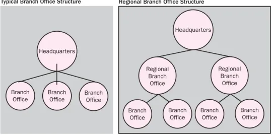
Branch Offices
A branch office is one that is ultimately controlled by a company but maintains a degree of autonomy. Banks, insurance companies, and large chains are examples of companies that traditionally maintain branch offices. A branch office likely will not keep up all the network services that the main office maintains. However, depending on the connection between the branch and the main office, it might be necessary to replicate some services in the branch office to help limit the flow of data over the connecting network.
Branch offices also do not typically act as links or hubs between other offices; each branch office is instead connected directly to a main office, as shown in Fig ure 1-3. There are exceptions to this, of course. In particularly large, distributed