Mechanochemical synthesis of hydrogen storage materials
J. Huot
a, D.B. Ravnsbæk
b, J. Zhang
c, F. Cuevas
c,⇑, M. Latroche
c, T.R. Jensen
b aUniversité du Québec à Trois-Rivières, 3351 des Forges, Trois-Rivières, Québec, Canada G9A 5H7 b
Center for Materials Crystallography (CMC), Interdisciplinary Nanoscience Center (iNANO), Department of Chemistry, Aarhus University, Langelandsgade 140, DK-8000 Århus C, Denmark
c
ICMPE, CNRS, UMR 7182, 2-8 rue Henri Dunant, 94320 Thiais Cedex, France
a r t i c l e
i n f o
Article history:
Received 13 April 2012 Accepted 9 July 2012 Available online 27 July 2012
a b s t r a c t
New synthesis methods are of utmost importance for most materi-als science research fields. The present review focuses on mecha-nochemical synthesis methods for solid hydrogen storage. We anticipate that the general methods and techniques are valuable with a range of other research fields, e.g. the rapidly expanding fields of ‘energy materials science’ and ‘green chemistry’ including solvent free synthesis. This review starts with a short historical reminder on mechanochemistry, followed by a general description of the experimental methods. The use of milling tools for tuning the microstructure of metals to modify their hydrogenation prop-erties is discussed. A section is devoted to the direct synthesis of hydrogen storage materials bysolid/gasreactions, i.e. by reactive ball milling of metallic constituents in hydrogen, diborane or ammonia atmosphere. Then,solid/solidmechano-chemical synthe-sis of hydrogen storage materials with a particular attention to ala-nates and borohydrides is surveyed. Finally, more specialised techniques such assolid/liquidbased methods are mentioned along with the common characteristics of mechanochemistry as a way of synthesizing hydrogen storage materials.
Ó2012 Elsevier Ltd. All rights reserved.
Contents
1. Introduction . . . 31 2. Tuning of metal microstructures by mechanical milling . . . 33 2.1. BCC alloys . . . 33
0079-6425/$ - see front matterÓ2012 Elsevier Ltd. All rights reserved.
http://dx.doi.org/10.1016/j.pmatsci.2012.07.001
⇑Corresponding author. Tel.: +33 1 49 78 12 25; fax: +33 1 49 78 12 03.
E-mail address:[email protected](F. Cuevas).
Contents lists available atSciVerse ScienceDirect
Progress in Materials Science
j o u r n a l h o m e p a g e : w w w . e l s e v i e r . c o m / l o c a t e / p m a t s c i2.2. Ti-based . . . 33
2.3. Mg-based BCC . . . 36
2.4. Amorphization . . . 38
3. Synthesis of hydrides by mechanically-induced solid/gas reactions. . . 39
3.1. Binary hydrides . . . 40 3.1.1. Magnesium hydride . . . 41 3.1.2. Titanium hydride . . . 42 3.1.3. Vanadium hydride . . . 42 3.2. Ternary hydrides . . . 43 3.2.1. ZrNi hydride . . . 43 3.2.2. TiNi hydride . . . 43 3.2.3. TiFe hydride . . . 43 3.2.4. LaNi5hydride . . . 43 3.2.5. TiV hydride . . . 44
3.3. Mg-based complex hydrides. . . 45
3.3.1. Mg2Fe hydride . . . 45 3.3.2. Mg2Co hydride . . . 48 3.3.3. Mg2Ni hydride . . . 49 3.4. Alanates . . . 51 3.4.1. Lithium alanates . . . 51 3.4.2. Sodium alanates . . . 52 3.4.3. Potassium alanates . . . 53
3.4.4. Mixed alkali alanates . . . 53
3.4.5. Alkali-earth alanates. . . 55
3.5. Synthesis of borohydrides by mechanical milling in diborane gas . . . 56
3.6. Synthesis of metal amides by mechanical milling in ammonia gas . . . 57
4. Synthesis of hydrides by mechanically-induced solid/solid and solid/liquid reactions . . . 57
4.1. Mechanochemical synthesis of metal borohydrides . . . 57
4.2. Synthesis of novel alane and metal alanates . . . 61
4.3. Novel quaternary hydrides . . . 64
4.3.1. Metal borohydride amides . . . 64
4.3.2. Metal alanate amides . . . 65
4.4. Solid–liquid mechanically assisted synthesis . . . 65
5. Final remarks and conclusions . . . 66
Acknowledgments . . . 67
References . . . 67
1. Introduction
Synthesis of innovative materials for energy conversion and storage has received increasing focus during the past decades due to the world´s increasing energy demands and simultaneous needs for environmentally friendly energy technologies. Hydrogen is recognized as a possible renewable energy carrier, but its large-scale utilization is mainly hampered by unsatisfactory properties of known hydrogen storage materials. Hence, preparation and characterization of novel materials are receiving
significant attention as reviewed elsewhere[1–4]. Traditionally, hydrogen storage materials, such as
metallic or complex hydrides, were prepared by solvent-based synthesis methods or by direct so-lid–gas hydrogenation reactions. However, during the past decade mechanochemical synthesis has become one of the most utilized preparation methods for this class of materials, and is still expected to hold a significant unexplored potential for development of novel approaches, e.g. for ‘green chem-istry’ including solvent free synthesis methods. In this work, recent progress within the experimental methods for preparation of hydrogen storage materials is surveyed.
In the mid-eighties, several research groups initiated the use of mechanical activation methods for
the synthesis of hydrides[5,6].Mechanical milling(MM) of mixtures of elements under inert gas
hydro-gen in an external device to form hydrides. This two-step approach allowed modifying the microstruc-ture of the alloy by milling to study its influence on the hydrogenation thermodynamics and kinetics [6–9]. Mechanical milling was very successful at improving hydrogenation kineticsviathe synthesis of nanocrystalline materials and simultaneous incorporation of selective additives during the milling
process[10–12].
Recently, it has been shown that Severe Plastic Deformation (SPD) techniques could be used for the
synthesis and processing of metal alloys and their hydrides[13–26]. A few specific cases will be
dis-cussed in the forthcoming sections. A possible advantage of SPD techniques over conventional milling is easier scaling up to industrial level. However, some specific nanocrystalline structures and nano-composites may only be synthesized through mechanical milling.
In the early nineties, solid–gas reaction facilitated by mechanical milling in reactive gases
(nitro-gen, oxygen and hydrogen) was investigated. This approach was initially designatedReactive
Mechan-ical Milling (RMM) and used for preparation of hydrides in hydrogen atmosphere [27]. The experiments were performed in small-sized milling vials under moderate hydrogen pressures (below 2 MPa), often leading to an incomplete reaction between hydrogen and metals. The extent of the
me-tal-hydrogen reaction was determined byex situXRD analysis of samples milled during a given period
of time[28,29]. Modern devices for RMM synthesis are now equipped with pressure and temperature
sensors that allow monitoring, e.g., hydrogen absorption during milling[30–32]. Hydrogenation
reac-tions can be followedin situas a function of milling time at working pressures up toca. 15 MPa.
Today, mechanochemical synthesis of metal hydrides using ball milling has grown to become one of the most frequently used methods. Typically, planetary ball mills are used, however other types
such as rotational, vibratory or attritor mills are also operated[33]. The different types of mills differ
in their milling efficiency and capacity and in some cases additional arrangements for cooling, heating,
gas loadingetc. can be applied. Typically a few grams of material and balls are placed in the planetary
ball mill to give a ball-to-powder weight ratio of 10:1–50:1. This approach offers the advantage that the milling vial can be loaded, sealed and unloaded under inert conditions in a glove box, and, if
equipped with valve connections, subsequently filled with reactive gas[30,31]. Thereby, thep,Tphase
space for mechanochemistry has expanded significantly.
In some cases, especially for ductile materials, a process control agent (PCA) could be added to
in-hibit particle agglomeration[33]. The PCAs can be solids, liquids, or gases. A wide range of PCAs has
been used in practice at a level of about 1–5 wt% of the total powder charge. The most common PCAs
are stearic acid, hexane, methanol, ethanol, graphite and salts[33].
Several parameters can be varied for the ball-milling synthesis: milling speed, total milling time, vial and ball composition, powder-to-ball weight ratio, vial diameter, ball diameter and density, mill-ing temperature, millmill-ing atmosphere and pressure of the selected gas. The latter two parameters re-quire a special high-pressure vial. Most planetary mills only allow controlling the speed of the support disk. The speed of the planets, on which the milling vials are mounted, is usually fixed relatively to the speed of the main disk. However, for special mills, such as the Fritsch Vario-Planetary Mill Pulverisette
4, both the speed of the support disk and the planets can be varied freely[34]. Thereby, the trajectory
of the balls within the vial may be controlled at least when the number of balls is low. Ideally the mill-ing can be continuously changed from high-energy mode dominated by high-energy ball–vial impacts
to a grinding mode where the balls mainly follow the circumference of the vial[35]. The latter is also
facilitated by a high number of balls in the vial. High-energy impacts tend to produce high mechanical pressure in the grain boundaries and in some cases make the high-pressure polymorph of the product. The grinding mode tends to produce more heat by friction and may in some cases lead to thermal decomposition of the product upon prolonged milling. Heating of the sample may be suppressed by using short periods of milling intervened by breaks where intrinsic heat produced in the grain bound-aries can be dissipated and the sample can thermally equilibrate. Therefore, not only the total milling time is important for obtaining the desired compound, but breaks within the period of milling is in some cases crucial, which possibly also reduce agglomeration of the powder on the vial walls and balls [36–42]. Furthermore, the reactant mixture, balls and vial can be placed in a fridge or freezer prior to milling to lower the temperature further and/or the milling can be intervened by cooling of the vial. Milling at cryogenic conditions, i.e. at liquid nitrogen temperature (77 K), known as cryo-milling, has
Within the past two decades, mechanochemistry has expanded widely both within the experimen-tal methods and techniques but also within the variety of materials that can be prepared, e.g. binary
and ternary metallic hydrides[43–47], or complex hydrides such as Mg-based transition metal
hy-drides[48–52], alanates[30,53–57], borohydrides[58], amides[59,60], and multi-component systems
[61–64]including the broadly studied Reactive Hydride Composites (RHC)[65–68]. These topics are the focus for further discussion in this review.
2. Tuning of metal microstructures by mechanical milling
The use of mechano-chemical methods for the synthesis and modification of hydrogen storage materials has generated an enormous amount of reports. In the last 10 years about a thousand papers have been published on the use of ball milling and mechanical alloying for this specific application. Therefore, this review focus on general aspects by discussion selected details and this section focus on the use of mechanochemical methods to tune the microstructure of metal hydride systems in order to improve their hydrogenation properties.
2.1. BCC alloys
A body-centered cubic (BCC) structure is a coarse packing structure and has more interstitial space
than face-centered cubic (FCC) and hexagonal close-packed (HCP) structures[69]. Thus, BCC alloys are
more attractive candidates to be explored as possible interstitial hydrogen storage materials. Usually, BCC alloys are synthesized by arc melting or induction melting. However, for some alloys the desired composition is difficult to obtain by using these techniques because the constituting elements may have quite different melting temperatures. With mechanical alloying there is in principle no limitation on the nature and number of the raw elements used. For hydrogen storage applications one could dis-tinguish two broad classes of BCC alloys: Ti-based and Mg-based. Each of these classes is discussed below.
2.2. Ti-based
BCC alloys of systems Ti–V–Mn and Ti–V–Cr have been intensively studied for hydrogen storage [70–75]. This class of alloys may also catalyse hydrogen release and uptake in magnesium [76].
Moderate hydrogen capacities as high as 3.6 wt% have been reported for Ti25V40Cr35alloy, which also
possess prolific kinetic and thermodynamic properties.
The effect of Severe Plastic Deformation (SPD) on BCC Ti–22Al–27Nb alloy has been investigated by
Zhang et al.[25,26]. They showed that the first hydrogenation (activation) was much faster for the
de-formed alloy compared to the as-quenched sample. The dede-formed alloy also had faster absorption/ desorption kinetics. However, the beneficial effect of deformation was lost after a few hydrogenation cycles. In these studies, SPD was obtained by cold rolling or compression. Cold rolling is a process by which a sheet metal or powder is introduced between rollers and then compressed and squeezed. In the case of cold rolling one rolling was performed at 10.5% and 80% thickness reduction. Some of the 80% rolled specimen were further rolled to 10% thickness reduction in a perpendicular direction with respect to the first rolling.
Huot et al. have made a systematic study of the effect of milling on TiV0.9Mn1.1alloy[77]. This
com-position is interesting to study because the as-cast alloy is a mixture of BCC andC14 phases. Therefore,
it is a good system to test the effect of milling on the crystalline change and the interaction between
phases. Milling was performed on as-cast alloy as well as on mixtures of elemental powders.Fig. 1
shows the effect of milling on as-cast TiV0.9Mn1.1.
The presence of NaCl Bragg peaks is explained by the use of a small amount of this salt as an
anti-sticking PCA. It is clear that, with milling time, theC14 phase vanishes and a FCC phase appears. From
Rietveld refinement it was found that, for the sample milled 80 h, the crystal structure is a mixture of cubic (FCC) solid solution phase and a BCC solid solution. The coexistence of FCC and BCC structures was also observed for the system Fe–Cu and may be due to an enhanced solubility due to the high
dis-location density[78]. When milling was performed on the raw elements (Ti, V, and Mn), an identical
result was obtained, i.e. formation of a nanocrystalline alloy composed of BCC and FCC phases[77].
The BCC alloys need activation, e.g. by cycling hydrogen release and uptake betweenp(H2) = 5 MPa
and vacuum at elevated temperature of 523 K. InFig. 2the hydrogen absorption and desorption
iso-therm (296 K) for arc-melted TiV0.9Mn1.1before and after 80 h of milling is presented. The maximum
capacity of the as-melted alloy is 1.9 wt% at 7 MPa which corresponds to an H/M ratio of 0.97. After 80 h of milling, the alloy does not absorb hydrogen up to 7 MPa. Because the as-milled materials pres-ent both FCC and BCC phases this means that none of them absorbs hydrogen. In the case of BCC phase the reason may be reduction of lattice parameters. Iron contamination (even at this low level) may
also play a role as shown by Santos et al. in the Ti–V–Cr system[79].
Fig. 2.Pressure–composition temperature (PCT) curve, at 313 K, of arc-melted TiV0.9Mn1.1alloy before and after 80 h of milling
Singh et al. studied the effect of milling an arc-melted Ti0.32Cr0.43V0.25alloy[80]. As they used
tung-sten carbide balls, some contamination was observed after long milling time. Ball milling did not affect the crystal structure of the alloy. Increase of ball milling time resulted in the increase in lattice strain and the decrease in crystallite size, which in turn increased sub-grain boundaries. Contamination from milling tools and microstructural changes caused an important decrease in the hydrogen storage
capacity[80].
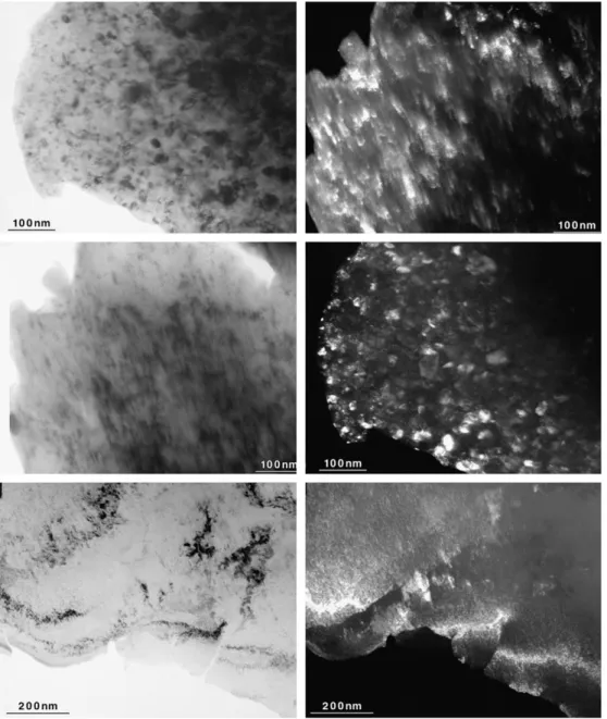
Fig. 3.TEM micrographs of TiV1.6Mn0.4after arc melting (top), after ball milled for 5 h (middle), and after 150 cold rolls
Amira et al. compared the effect of ball milling and cold rolling for Ti–Cr system[81]. Unlike ball
milling, cold rolling of TiCrx(x= 2, 1.8, 1.5) did not lead to the formation of metastable BCC phase.
However, cold rolling was found to be effective to form nanocrystallineC14 Laves phase. Hydrogen
sorption experiments showed that cold-rolled alloys have similar hydrogen sorption properties to ball-milled alloys despite different crystal structures.
The alloy TiV1.6Mn0.4has been recently investigated by Couillaud et al.[82]. The effect of extended
cold rolling as well as high energy ball milling was a reduction of crystalline size and lattice parameter
but no change in the crystal structure.Fig. 3shows TEM micrographs of TiV1.6Mn0.4alloy in the
as-cast, milled, and cold-rolled states.
The dark field image shows that all samples are nanocrystalline. The bright field image of the cold-rolled sample clearly shows the pile-up of dislocations. The dark field image shows that, contrary to
the as-cast and ball-milled samples, the crystallites tend to be aligned along dislocations.Fig. 4shows
the X-ray diffraction patterns of as-cast, milled 5 h and cold rolled 150 times TiV1.6Mn0.4alloy.
From these X-ray powder diffraction patterns it was determined that the crystallite sizes of as-cast,
milled, and cold-rolled samples are respectively 17, 11, and 13 nm[82]. Apart from peak broadening
due to the reduction of crystallite size, the pattern of the ball-milled sample has the same relative intensities and lattice parameter as the as-cast sample. For the cold-rolled sample, the lattice param-eter is also the same as the as-cast sample but there is a very strong texture along (200), which is a common feature of cold-rolled samples. Neither the ball-milled sample nor the cold-rolled samples absorb hydrogen even after 10 cycles of hydrogen pressurization (10 MPa) and vacuum at 423 K. The reason for this significant loss of hydrogen capacity is still not clear.
2.3. Mg-based BCC
Recently, Mg-based BCC alloys have been explored in order to achieve higher gravimetric hydrogen storage capacity. In particular, Akiba’s group has made an extensive study of the synthesis of Mg–Ti [83,84], Mg–Co[85–87], and Mg–Ni[88,89]BCC alloys by means of ball milling. In this review we will limit our discussion to the Mg–Ti system.
Binary Mg–Ti alloys are being intensively investigated for various applications such as: negative
electrodes for Ni–MH batteries[90,91], H2sources for fuel cells[84,92], switchable mirrors for smart
solar collectors[93,94], and optical hydrogen detectors[95]. In the Mg–Ti phase diagram equilibrium
solid solubility of each metal in each other is less than 2 at.% and no intermetallic compound is found. Therefore, non-conventional synthesis methods based on melting or sintering can be used. Metastable single-phase Mg–Ti thin films have been successfully synthesized over a large compositional range by
means of electron-beam and magnetron co-sputter deposition techniques[90,93,94,96,97]. However, these techniques could not be scaled-up to industrial level and other methods have to be investigated. Mechanical alloying has demonstrated its high efficiency for producing metastable Mg–Ti alloys
start-ing from elemental Mg and Ti powders[83,91,98–101].
The synthesis of Mg–Ti BCC alloys by mechanical alloying has been extensively studied by Asano
et al.[83,84,92,100,101]. Although both Mg and Ti have a hexagonal closed packed (HCP) structure,
during milling of a Mg and Ti mixture they react differently. In the case of magnesium, the
deforma-tion is mainly by basal plane slip {0 0 0 1}h1 21 0iwhile for titanium twinning deformation is more
important[100]. In one investigation, Asano et al. had the idea of adding lithium to magnesium in
or-der to reduce the yield stress of magnesium and also to decrease its lattice parameter[100]. They
found that by adding Li to Mg, the deformation of Mg was easier and the Ti crystallite size was re-duced. This led to a decrease of synthesis time for BCC phase formation.
In a subsequent study, they first synthesized a BCC Mg50Ti50alloy by ball milling a mixture of
50Mg + 50Ti in a Fritsch P5 planetary ball mill for 150 h at a rotation speed of 200 rpm.Fig. 5confirms
that a BCC phase was obtained, and from the peaks width a crystallite size of 3 nm was determined [84].
A full hydrogenation at 423 K under 8 MPa of hydrogen and for 122 h resulted in the formation of
Mg42Ti58H177FCC hydride phase and some MgH2.
By controlling milling conditions and Mg:Ti ratio, Asano et al. have also shown that BCC, FCC or HCP
phase could be obtained in the Mg–Ti system[83]. In the case of HCP phase it is formed by solution of
Ti into Mg while the BCC phase is produced by solution of Mg into Ti and the FCC phase is stabilized by
introduction of stacking faults in Mg and Ti which have a HCP structure[83,84]. If MgH2is used
in-stead of Mg as the starting material then, after ball milling a 50MgH2+ 50Ti mixture, the resulting
compound is FCC Mg33Ti50H94plus some MgH2[92]. The importance of mechanical effect during
mill-ing is discussed in ref[101]. It shows that during ball milling of Mg and Ti powders in molar ratio of
1:1, plate-like particles first stuck on the surface of the milling pot and balls. After these plate-like par-ticles fell off from the surface of the milling pot and balls, spherical parpar-ticles, in which concentric lay-ers of Mg and Ti are disposed, are formed. These particles have an average diameter of 1 mm. These
spherical particles are then crushed into spherical particles with a diameter of around 10
l
m byintro-duction of cracks along the boundaries between Mg and Ti layers. Finally, the Mg50Ti50BCC phase with
a lattice parameter of 0.342(1) nm and a grain size of 3 nm is formed. During milling, Ti acts as an
abrasive for Mg which had stuck on the surface of the milling pot and balls[101].
Recently, Çakmak et al. showed that mechanical milling of Mg–10 vol% Ti yields large Mg
agglom-erate, 90–100
l
m, with embedded Ti fragments of about 1l
m uniformly distributed within theagglomerates[102]. These Mg agglomerates are made of coherently diffracting volumes (crystallites)
of small size. Crystallite size, as determined with X-ray diffraction analysis, can be as small as 26 nm after 30 h of milling.
In an investigation of high-energy milling of 50Mg–50Ti mixture, Maweja et al. observed twinning
in Ti-rich crystallites at intermediate milling time[103]. They attributed the twinning to the
deforma-tion of Ti particles. But they also pointed out that in the Mg–Ti system it might also indicate a
strain-induced martensitic transformation of the metastable
x
-FCC into BCC. The crystallite boundariesacted as preferential sites for the heterogeneous nucleation of the twins and for the formation of solid
solution by release of the lattice strain energy[103].
For electrochemical applications, mechanical alloyed Mg–Ti materials must be activated by adding of few at.% of Pd. Rousselot et al. have shown that if a 50Mg–50Ti mixture is pre-milled before adding
Pd then the alloying of Pd with pre-milled Mg50Ti50occurs very rapidly (few minutes) and is complete
after 5 h of milling[104]. They also found that the crystalline structure of the Mg50Ti50alloy (BCC and
HCP Mg–Ti phase mixture) does not change significantly with the addition of Pd.
2.4. Amorphization
In amorphization under mechanical driving forces, two categories of alloys could be defined[105].
The first category consists of intermetallic compounds induced to undergo polymorphic crystal-to-amorphous transformation by deformation. In this process the introduction of defects by milling in-creases the free energy of the equilibrium alloy such that it goes above the free energy of the amor-phous state. Thus, the amoramor-phous phase becomes the lowest free energy state and the alloy becomes amorphous. The second category of amorphous alloys contains those formed by intermixing of individual elements that have a negative heat of mixing. In this case, deformation plays the role of
enhancing such energy-lowering reactions through deformation-enhanced interdiffusion[105].
From a systematic study of Mg–Ni system, Rojas et al. proposed the sequence of phase
transforma-tions during milling leading to amorphization as[106]:
c-Mgþc-Ni!nc-Mgþc-Ni!amorphousþnc-Niþnc-Mg !amorphousþnc-Niþnc-Mg2Ni!nc-Mg2Ni
where c and nc denotes crystalline and nanocrystalline state, respectively. The first step shows the fact that grain refinement in nickel is slower than in magnesium. It has been demonstrated that the grain
size attainable by milling depends on the crystal structure of the material being milled[107]. Usually,
BCC materials tend to reach the smallest sizes, HCP materials somewhat larger grain sizes, and FCC materials tend to produce the largest grain sizes. Since the crystal structure of Mg is HCP and that of Ni is FCC, such a difference in the grain size after milling is expected.
For Mg–Ni system, amorphous phase could be prepared by ball milling in less than 10 h[108].
According to Varin et al., the presence of hard MgNi2phase helps to reduce crystallite size of Mg2Ni
phase and thus facilitates amorphization[109,110].
For some compositions and milling parameters, a crystallization–amorphous–crystallization
phe-nomenon could appear. One example of this was given by El-Eskandarany et al. for Co75Ti25[111].
A solid-state reaction took place during milling elemental Co and Ti powders and an amorphous phase
of Co75Ti25was formed after 3 h. They showed that this amorphous phase crystallized into an ordered
FCC-Co3Ti phase upon heating to 880 K. Further milling to 24 h also leads to crystallization and the
formed phase was a metastable BCC-Co3Ti nanocrystalline phase. They attributed this transformation
taking place in the ball mill to the inability of the formed amorphous phase to withstand the impact and shear forces that are generated by the milling media. When the milling time was further increased to 100 h, the crystalline phase was subjected to several points and lattice defects that raised the free
energy from the stable BCC-Co3Ti phase to an amorphous less stable phase. In this case, the
crystal-line–amorphous transformation which took place was similar to the mechanical grinding method in which the amorphization occurs by relaxing the short-range order without any compositional changes. Further milling leads to the formation of crystalline and/or amorphous phases depending on the milling time. Contamination from milling tools and temperature effect were ruled out as origin
of this phenomenon[111].Fig. 6shows a schematic illustration of this crystallization–amorphization–
3. Synthesis of hydrides by mechanically-induced solid/gas reactions
Mechanical millingof metal powders under reactive gas, i.e.Reactive Mechanical Milling(RMM), is becoming a mature and powerful technique for the synthesis of metallic and complex hydrides. The mechanical treatment induces a chemical reaction between the solids and the gas. The synthesis of several metallic and complex hydrides by RMM is surveyed here. RMM under hydrogen gas allows for the synthesis of binary and ternary metal hydrides, Mg-based complex hydrides and alanates. More recently, this technique has been extended to other reactive gases such as diborane and ammo-nia for the synthesis of borohydrides and metal amides, respectively. Some particular phenomena such as ultra-fast hydride synthesis, reactive-milling induced amorphization, and multi-step reactions are reported. The obtained hydrides are typically nanocrystalline materials leading to fast kinetic for hydrogen release and uptake reactions useful for hydrogen storage applications.
Significant progress on the understanding of RMM process has been provided by thein situ
mon-itoring of the hydrogenation reaction during milling. In 2000, Dunlap et al. connected a ball-milling
device to a large hydrogen reservoir by means of a rubber tube[112]. They could follow the hydrogen
uptake as a function of milling time for several early transition metals (Ti, Zr, Hf, V, Nb and Ta).
Exper-iments were conducted near atmospheric pressure (p(H2)0.1 MPa). A similar method was used by
Bellosta et al. to monitor hydrogen release during ball-milling of sodium tetra-alanate with TiCl3
addi-tive[113]. Hydrogen release occurs due to titanium reduction to the zero-valent state on milling. A further improvement was reached by using telemetric systems instead of mechanical connections toin situregister both hydrogen pressure and vial temperature during milling[30,31]. The sensors were mounted on the lid of a stainless steel vial which was able to withstand high pressure
Fig. 6.Schematic illustration of amorphous–crystalline–amorphous cyclic phase transformations that took place during
(10 MPa). Under these conditions, the one-step direct synthesis of Ti-doped NaAlH4using NaH, Al
and TiCl3as starting powders could be monitored.
RMM is generally accomplished in tight stainless steel vials equipped with a connection valve for vacuuming and hydrogen filling. The vial is then placed in a milling device to promote the
mechano-chemical reaction leading to the hydride formation. For practical reasons regardingp–Tgauges
attach-ment to vials, most of current milling devices used for RMM are planetary ball mills. Thus, this
preparation technique is widely named as reactive ball milling. Nonetheless, also shaker, attritor,
and vibration mills have been used successfully[51,112,114,115].
Today, compound synthesis can be anticipated from thein situmonitoring of the hydrogenation
reaction and subsequently verified byex situcrystallographic and chemical analyses. Furthermore,
if thermodynamic parameters such as vial volume and gas pressure and temperature are accurately known, the quantity of absorbed hydrogen as a function of time can be reliably obtained. Zhang
et al. have recently shown that hydrogen uptake can be determined with an accuracy of 95%[116].
In situmonitoring of changes in gas pressure is certainly a powerful tool for the study of hydride
for-mation kinetics and reaction mechanisms on reactive milling.
3.1. Binary hydrides
Though thermodynamically favourable, the formation ofAHxbinary hydrides by solid–gas reaction
between hydrogen gas and a metal (A, a metal with strong affinity for hydrogen, here stands for either
alkaline earths (Mg) or early transition metals such as Ti and V) is very often hindered by kinetic bar-riers related to the presence of native oxide layers at the metal surface. Then, severe treatments at high temperature (typically above 700 K) and high pressure (several MPa) are needed in conventional gas-phase hydrogenation for activation. In the course of these treatments, oxygen at the surface might react with the bulk material leading to additional impurities. Such surface limitation can be overcome by RMM of pure metals in hydrogen atmosphere that allows achieving faster synthesis reactions under more moderate conditions. Synthesis conditions by RMM under hydrogen gas of representative binary
hydrides are summarized inTable 1.
Table 1
Representative binary and ternary metal hydrides synthesised by RMM under hydrogen gas. The employed device, reactants, initial hydrogen pressure,p(H2), total milling time (tmt), milling speed (ms), ball-to-powder weight ratio (BTPWR) and ball diameter (Bd)
are given.
Compound Device Reactants p(H2) (MPa) tmt (h) ms (rpm) BTPWR Bd (mm) Ref.
MgH2 Planetary Mg 0.34 25 12 [117] MgH2 Mg + graphite 0.4 1 10:1 [118] MgH2 Fritsch P6a Mg 1–9 8 500 10:1 10 [31] MgH2 Fritsch P4a Mg 8 2 400 60:1 12 [64] TiH1.9 Planetary Ti 0.34 5.5 12 [117] TiH2 Fritsch P4a Ti 8 0.16 400 60:1 12 [64] VHx Fritsch P5 V 1 0.17 400 30:1 7 [47]
ZrNiH3 Fritsch P5 ZrNi 2 3 30:1 10 [27]
ZrH2+ Ni Fritsch P5 Zr + Ni 2 3 30:1 10 [27]
ZrH2+ NiZryHx Fritsch P5 Zr + Ni 2 100 30:1 10 [27]
b-ZrNiH Fritsch P7 ZrNi 0.1 0.08 400 30:1 7 [28]
c-ZrNiH3 Fritsch P7 ZrNi 1 0.08 400 30:1 7 [28]
TiNiH3 Rod-mill Ti + Ni 0.1 200 30:1 10 [119]
TiH2+ Ni Ti + Ni 1.1 40 250 10:1 10 [120]
TiH2+ Fe Spex 8000 TiFe 0.5 7 8:1 6, 12 [114]
a-LaNi5H0.15 Fritsch P7 LaNi5 1 0.08 400 30:1 7 [121]
amph-LaNi5yHx Fritsch P7 LaNi5 1 10 400 30:1 7 [121]
BCC TiVH0.9 Fritsch P5 TiV or Ti + V 0.2 100 20:1 10 [43]
TiVH2.8 Fritsch P5 TiV or Ti + V 0.4 100 20:1 10 [43]
FCC TiVH4.7 Fritsch P5 TiV or Ti + V 1 100 20:1 10 [43]
Ti0.20V0.78Fe0.02H2 Fritsch P4* Ti0.20V0.78Fe0.02 8 0.17 400 100:1 12 [122]
a
3.1.1. Magnesium hydride
Magnesium hydride is classically prepared by reaction with hydrogen gas and Mg powder at tem-peratures around 700 K and hydrogen pressures in the range 7–8 MPa for several hours. However, even under these conditions, the presence of Mg is often detected by XRD as the reaction is not
completed[123]. Indeed, a shell of magnesium hydride is reported to form at the surface of
microm-eter-sized magnesium grains, blocking further hydrogenation of the remaining metal core[124,125].
Consequently, the hydrogenation rate of bulk magnesium is slow.
First attempts to form magnesium hydride by RMM were conducted by Chen and Williams using
p(H2) = 0.34 MPa and a vertical planetary mill[117]. Complete formation of MgH2hydride is reported
to occur after long milling time (25 h). Later, similar experiments under 0.5–1 MPa of hydrogen
pres-sure were conducted by different groups[46,126,127]. Neither of them could attain hydride formation
above 50 wt%, which was attributed to kinetic effects. This was finally overcome by performing RMM experiments at high temperature (573 K) with the addition of graphite to obtain complete
hydrogena-tion within 1 h[118]. Graphite could act as a PCA to reduce particle agglomeration by cold-welding
[33].
Doppiu et al. have however shown that fast MgH2formation can also be achieved near room
tem-perature using high-pressure reactive ball milling[31]. The hydrogenation reaction could be
moni-tored byin situmeasurements of both pressure,p, and temperature,T, inside the vial during milling
by using on-board sensors and radio transmitted data. Syntheses were done with pure Mg powders ball milled with a ball-to-powder weight ratio of 10:1 at 500 rpm and hydrogen pressures of 1, 4 and 9 MPa. From the data collection, it was first observed that the temperature of the vial increases up to 318 K mainly due to mechanical action. Mg absorbs hydrogen in less than 8 h for pressures larger than 4 MPa. Reaction rate was significantly slower for lower pressure (1 MPa). Moreover, a nucleation time, strongly dependant of the pressure is also reported; almost undetectable at 9 MPa, it reaches more than 2 h at 1 MPa. Further investigations by XRD at different milling times show the formation
of the metastable orthorhombic
c
-phase along with the tetragonalb-MgH2one. Thec
-phase can alsobe achieved by ball milling of magnesium hydride[128]. With increasing milling time, the crystallite
size decreases to finally stabilizing at 10 nm. Same amounts of hydride phases (>95 wt% for
c
+b) andidentical crystallite sizes are obtained after 18 h of milling whatever the initial pressure though the rate of formation and the size reduction were faster for higher pressures. This was interpreted on the basis of two different factors. Higher pressures promote a more rapid formation of the hydride that
is in turn known to exhibit higher plastic deformation. Then, for higher amounts of MgH2, the
mechan-ical action is more effective than for ductile Mg. However, it is worth noting that at long milling times, all samples reach the same chemical and microstructural states.
Very similar results are also reported by Doppiu et al. who performed reactive milling of an
ele-mental Mg87Ni10Al3powder mixture under hydrogen atmosphere[129]. Milling induces the synthesis
of nanocrystalline MgH2at the first stage followed by the formation Mg2NiH4when a high degree of
conversion of Mg in the hydride form was reached. A minimum value for the crystallite size of 8 nm
0 60 120 180 5.0 5.5 6.0 6.5 7.0 7.5 8.0 8.5 9.0 300 304 308 312 316 320 P (MPa) t (min) T (K)
(A)
0 60 120 180 0.0 0.5 1.0 1.5 2.0 H/Mg t (min)(B)
Fig. 7.Evolution of the pressure and temperature (A) during RMM of magnesium in hydrogen gas and the calculated H/Mg ratio
was obtained. Small differences in the hydride stability were observed at different milling times. In spite of the oxidation of the sample, fast absorption–desorption kinetics were obtained.
A typical example of the evolution of the pressure, the temperature and the H concentration as a
function of time during RMM of Mg is shown inFig. 7. The starting material was coarse magnesium
powder to reduce the amount of MgO that may develop at the grain surface of powder material.
The milling vial was loaded withp(H2) = 8 MPa and operated at 400 rpm. After initial heating due
to ball friction, the pressure drop related to hydride formation is observed and the reaction is
com-pleted after 2 h. The final H/M value reaches 1.9, a value 5% smaller than expected for MgH2. XRD
anal-ysis shows that the final product is made of 76 wt% ofb-MgH2, 21 wt% of
c
-MgH2, and 3 wt% of MgO.The mean crystallite size for the hydride phases is close to 6 nm, in good agreement with previous results.
3.1.2. Titanium hydride
The formation of titanium hydride by RMM with composition TiHl.9was first reported by Chen and
Williams in 1995 using a hydrogen filled containerp(H2) = 0.34 MPa for 67 h[117]. The hydrogenation
reaction was completed in 5.5 h and the TiH1.9compound was stable during prolonged milling, with
only a reduction of particle size being observed. Very similar results have been published by different
groups[44–46]. Dunlap’s group has extended this method to other early transition metals such as Zr,
Hf, Ta, Nb and V[112].
Short reaction time was explained in terms of clean surface generation and severe reduction of dif-fusion path. Titanium powder is initially passivated by the presence of surface oxides. Upon milling, fresh and highly reactive surfaces are created promoting the formation of near-surface hydride precip-itates. This causes hydrogen embrittlement of the metal, enhances its pulverisation and results in a shorter diffusion path for hydrogen absorption.
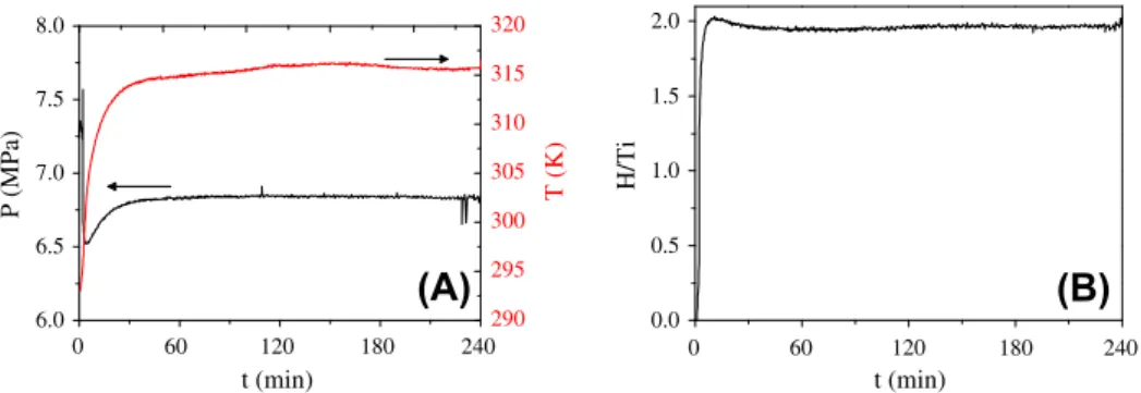
The formation of hydride TiH2during RMM is shown inFig. 8 [64]. Contrary to magnesium, no
nucleation time is observed and the hydride formation proceeds readily and is completed after
10 min. XRD analysis confirms the formation of TiH2 though small contamination with iron is
ob-served, most probably due to the stainless steel vial abrasion during milling. The mean particle size determined from the diffraction peak widths is around 7 nm.
3.1.3. Vanadium hydride
Orimo et al. reported on the preparation of nanostructured VHxprepared by mechanical milling
un-der H2atmosphere[47]. Formation of theb2phase was observed after 5 min of milling at room
tem-perature whereas conventional gas-phase hydrogenation would need activation treatments under
600 K and 3 MPa. The grain size of the b2 phase decreases from 80 nm at 5 min milling time to
10 nm after 60 min. Additional milling time (up to 300 min) does not lead to further decrease of
the grain size nor the formation of an amorphous state as theb2phase remains in crystalline state.
From the relationship between hydrogen concentration and unit cell, the hydrogen concentration
6.0 6.5 7.0 7.5 8.0 290 295 300 305 310 315 320 P (MPa) t (min) T (K)
(A)
0 60 120 180 240 0 60 120 180 240 0.0 0.5 1.0 1.5 2.0 H/Ti t (min)(B)
Fig. 8.Evolution of the pressure, the temperature (A) and the H concentration (B) as a function of time during RMM of titanium
was determined as a function of the grain size. It decreases from 0.82 H/M for 80 nm down to 0.72 H/
M for 10 nm indicating a modification of theb2–
c
phase boundary in the V–H system for nanometergrain sizes. Lower concentration, nearly independent of the grain size and higher diffusivity of hydro-gen are also reported in the intergrain domain.
3.2. Ternary hydrides
Ternary metal hydrides of general compositionABHxcan be easily synthesized by RMM providing
that the hydrides are stable under the pressure and temperature milling conditions. In this
formula-tion,Astands for a metal with strong affinity for hydrogen (an early transition or rare-earth metal) and
Bstands for a metal with weak hydrogen affinity (a late transition metal). Well-known hydrogen
stor-age intermetallic compounds such as ZrNi, TiFe, TiNi and LaNi5have been used in RMM experiments
(seeTable 1). As a general behaviour, two effects are observed on prolonged milling: formation of
amorphousABHxhydrides and compound disproportionation intoAHx+Bspecies. Compound
amor-phization is driven by the large negative heat of mixing betweenAandBelements while its
dispro-portionation is favoured by the different affinity between both elements for hydrogen.
3.2.1. ZrNi hydride
RMM experiments in the Zr–Ni system have been first reported by Aoki et al.[27]. They performed
RMM (p(H2) = 2 MPa) of both arc-melted ZrNi alloys and equiatomic Zr and Ni powder mixtures. In the
first case, ZrNiH3hydride is formed after 3 h of milling. On prolonged milling (over 100 h), the
crys-tallite size of the hydride decreases without apparent amorphization. The lack of amorphous phases
is attributed to the difficulty to introduce defects in ZrNiH3hydride because of its brittleness. For
RMM of elemental powders, a mixture of ZrH2 and elemental Ni is formed at short milling time
(<3 h). Further reaction over 100 h leads to the coexistence of ZrH2and amorphous Zr-poor NiZr1yHx
phase.
Orimo et al. have studied the effect of hydrogen pressure during RMM of ZrNi compound within the
range 0–1 MPa[28].b-ZrNiH and
c
-ZrNiH3hydrides are formed within 5 min of milling. Phaseabun-dance depends on hydrogen pressure. Formation of the most stableb-hydride is observed at 0.1 MPa,
whereas that of the less stable
c
-hydride occurs at 1 MPa. At intermediate pressures, 0.3 MPa, bothphases are detected. As observed by Aoki, prolonged milling over 80 h results in the formation of
ZrH2and amorphous Zr-poor NiZr1yHxphase. Such decomposition reaction seems to be delayed with
increasing hydrogen pressure.
3.2.2. TiNi hydride
RMM experiments (p(H2) = 0.1 MPa) on equiatomic Ti and Ni powder mixture have been conducted
in a rod-milling device[119]. Within the first 3 h of milling metallic Ti transforms to TiH2and metallic
FCC Ni remains unreacted. Further milling up to 200 h leads to the gradual formation of a
nanocrys-talline (10 nm) single-phase FCC compound. The compound is described as an FCC TiNiH3solid
solu-tion, though details on the hydrogen content determination are not provided. This result is rather striking since TiNi compound only absorbs 1.4 H/f.u. under normal conditions of pressure and
temper-ature[130]. In fact, later experiments at higher hydrogen pressure (1.1 MPa) failed to get the solid
solution TiNiH3phase[120]. Instead, formation of poorly crystallized TiH2and Ni phases on milling
for 40 h is reported.
3.2.3. TiFe hydride
Chiang et al. have performed RMM experiments (p(H2) = 0.5 MPa) in TiFe compound[114].In situ
manometric measurements reveal that a total hydrogen uptake of 1.6 H/f.u. occurs within 7 h of
mill-ing formmill-ing TiFeH1.6.Ex situXRD analysis reveals that the ternary hydride decomposes to TiH2and Fe.
3.2.4. LaNi5hydride
Fujii et al. have performed RMM experiments (p(H2) = 1 MPa) on LaNi5alloy and observe formation
of solid solution
a
-LaNi5H0.15within the first 5 min of milling[121]. Formation of hydrideb-LaNi5H61 MPa at the temperature attained on milling. At longer milling times, 5 min <t< 3 h, the
a
-phase coexist with an amorphous phase. This phase forms faster in the presence of hydrogen than inball-milling experiments performed under inert gas. The
a
-phase decomposes into Ni and amorphousNi-poor LaNi5yHxphase upon prolonged milling, 3 h <t< 10 h. Subsequent thermodynamic
measure-ments show a significant reduction of total and reversible hydrogen storage capacity for long-time
milled as compared to pristine LaNi5compound. This is attributed to a lower hydrogenation capacity
of both poorly crystallized inter-grain and amorphous regions as compared to the microcrystalline state. This concurs with the facts that nanocrystalline systems exhibit lower capacity than microcrys-talline ones and that hydrogen binding energies expands over a wide energy range in amorphous sys-tems[131,132].
3.2.5. TiV hydride
One should notice that the Ti–V system differs from previous ones as concerns the affinity of con-stituting elements towards hydrogen. Both elements are A-type and exhibit comparable affinity for hydrogen which, in principle, precludes alloy disproportionation by hydrogenation. Furthermore, this system exhibits small heat of mixing so that alloy amorphization is expected to be difficult.
RMM (p(H2) = 0.2,0.4 and 2 MPa) of either equiatomic Ti and V powder mixtures or BCC TiV alloy
have been conducted by Aoki et al.[43]. At long milling time (100 h), phase constitution of milled
products does not depend on the nature of the initial powder. Hydrogen pressure plays, however, a
major role. At low (0.2 MPa) and high (1 MPa) pressures, BCC TiVH0.9solid solution and FCC TiVH4.7
hydride are formed, respectively. The hydrogen content of FCC TiVH4.7hydride is probably
overesti-mated since maximum hydrogen uptake of both Ti and V is 2 H/M. Nevertheless, both BCC and FCC hydrogenated phases are crystalline. In contrast, at intermediate pressure (0.4 MPa), amorphous
TiVH2.8phase is obtained. The formation mechanism of this phase depends on the initial reactants.
For Ti + V powder mixture, the amorphous phase is formed by reaction between TiH2and V, whereas
for the arc-melted alloy it results from gradual amorphization of BCC TiVH2.8phase on milling.
Strik-ingly, for both cases, the amorphization reaction occurs without changing the hydrogen content.
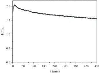
RMM experiments on a BCC Ti–V–Fe alloy of composition Ti0.20V0.78Fe0.02have been carried out in a
device equipped withpandTsensors at rotation speed of 400 rpm andp(H2) = 8 MPa. The
hydroge-nation curve is shown inFig. 9 [122]. The alloy absorbs 2 H/f.u. in only ten minutes indicating the
for-mation of a stoichiometric (Ti,V,Fe)H2hydride. Further milling produces hydrogen desorption from the
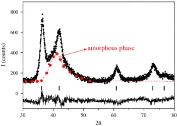
milled sample. Its hydrogen content decreases to 1.55 H/f.u. after 8 h of milling. XRD diffraction
anal-ysis (Fig. 10) shows that the RMM alloy consists of a mixture of FCC VH2-type hydride and amorphous
0 60 120 180 240 300 360 420 480 0.0 0.5 1.0 1.5 2.0 H/f.u. t (min)
phase. The amorphous phase formation accounts for the spontaneous hydrogen desorption on milling since it stores less hydrogen.
3.3. Mg-based complex hydrides
Mg-based Mg2THxternary hydrides (T= Fe, Co and Ni transition metals) are attractive hydrogen
storage materials due to their high specific (5.5, 4.5 and 3.6 wt%) and volumetric (150, 125 and
97 g/L) hydrogen contents for Mg2FeH6, Mg2CoH5and Mg2NiH4, respectively[138]. The synthesis of
these hydrides is problematic due to the great difference in vapour pressure and melting point
be-tween Mg andTand the lack of stable Mg2Fe and Mg2Co intermetallic compounds in their respective
binary phase diagrams. From these facts, synthesis of Mg2THx ternary hydrides was classically
achieved by sintering methods from elemental powder mixtures. Temperatures and hydrogen
pres-sures as high as 750 K and 9 MPa, respectively, and reaction time of several days are required[139].
Synthesis conditions of Mg2THx ternary hydrides by RMM under hydrogen gas are summarized in
Table 2.
3.3.1. Mg2Fe hydride
The synthesis of Mg2FeH6by RMM (p(H2) = 1 MPa for 20 h) of Mg and Fe powder was first
at-tempted in 1997[133]. Mg2FeH6hydride was not obtained but Mg powder got hydrogenated to form
intimate MgH2–Fe mixture. The failure to form the ternary hydride could be due to milling conditions
not being sufficiently efficient (ball-to-powder weight ratio of 4:1). It was later discovered that the desired hydride can be obtained in two different ways. The first simply consists in a sintering
treat-ment of the reactive milled product MgH2–Fe for one day at 625 K under 5 MPa of hydrogen. The
sec-ond, more complex, was reported in a subsequent paper[134]. Mechanical milling of MgH2and Fe
powders in molar ratio 2:1 under argon atmosphere was performed for 60 h in a high-energetic shaker mill with ball-to-powder weight ratio of 10:1. The mechanical energy provided under these milling
conditions was high enough to promote Mg2FeH6 formation without subsequent sintering. Much
probably, the following solid-state reaction takes place:
3MgH2ðsÞ þFeðsÞ !Mg2FeH6ðsÞ þMgðsÞ ð1Þ
The formation of the ternary compound is driven by the fact that the Mg2FeH6phase is more stable
than MgH2[140].In situSR-PXD patterns measured for a ball milled sample of MgH2–Fe (2:1) reveal
formation of Mg2FeH6at673 K atp(H2) = 10 MPa[141].
30 40 50 60 70 80 0 200 400 600 800 I (counts) 2θ
amorphous phase
Fig. 10.Rietveld analysis of Ti0.20V0.78Fe0.02alloy after RMM for 480 min. Observed (dots), calculated (top line) and difference
curves (bottom line) are shown. Vertical bars (|) correspond to Bragg positions (Cu Ka1,2) for FCC VH2-type hydride. Large dots
In 2002, direct though incomplete synthesis of Mg2FeH6by RMM of elemental powders was
simul-taneously reported[49,115]. Gennari et al. used a Uni-Ball-Mill II device under 0.5 MPa with hydrogen
refilling every 5 h to maintain constant hydrogen pressure in the vial[49]. Mg2FeH6formation with a
yield of 28 wt% was achieved after 60 h of milling. The synthesis was reported to occur in two steps.
MgH2is formed during the first 40 h by mechanically activated solid–gas reaction followed by the
so-lid-state reaction between MgH2and Fe at longer milling times. Raman et al.[115]used a Szegvari
attritor device under 1 MPa of hydrogen. The ternary hydride started forming after 14 h of milling and a maximum yield of 63 wt% was achieved at 20 h of milling as determined from XRD analysis. Reaction yield is probably overestimated since a high quantity of Fe (37 wt%) was identified as the un-ique secondary phase, which is not possible from mass-balance considerations. In fact, significant residuals in the Rietveld analysis likely related to MgO phase can be observed, which explains the
presence of unreacted Fe (similar effects have been later observed[50]). Crystallite sizes of 12 and
18 nm are reported for Mg2FeH6 and Fe phases, respectively. Formation on MgH2as intermediate
phase was not detected. Prolonged milling to 30 h is reported to lead to amorphization of the ternary hydride.
Milling under hydrogen of 2MgH2+ Fe and 2Mg + Fe powder mixtures have also been compared
[142]. It was found that a faster reaction and higher yield is achieved for elemental powders as
com-pared to 2MgH2+ Fe. The differences were attributed to the dissimilar mechanical properties and
microstructures of the mixtures. The 2Mg + Fe mixture behaves as a ductile–ductile pair that results in a higher contact surface between Mg and Fe, and a better intermixing and size reduction. On the
contrary, the 2MgH2+ Fe mixture performs as a ductile–brittle combination, with less contact area
be-tween the reactants and hence lower yield and longer synthesis time.
In 2008, the direct synthesis of Mg2FeH6by RMM of elemental powders was monitoredin situby
manometric means by Baum et al.[51]RMM experiments were performed in a horizontal vibrating
mill operated at 32 s1under a hydrogen pressure of 0.3 MPa. In spite of using mild milling conditions
(one unique ball and ball-to-powder weight ratio of 16:1), the reaction was completed after only 8 h of milling time. The reaction yield is not specified, but judging from the total hydrogen uptake and XRD Table 2
Mg-based complex hydrides synthesised by RMM under hydrogen gas. The employed device, reactants, initial hydrogen pressure,
p(H2), total milling time (tmt), milling speed (ms), ball-to-powder weight ratio (BTPWR), ball diameter (Bd), reaction yield and
formed side products are given.
Compound Device Reactants p(H2)
(MPa) tmt (h) ms (rpm) BTPWR Bd (mm) Yield (wt%) Side products Ref. Mg2FeH6 Fritsch P5 2Mg + Fe 1 20 325 4:1 10 0 MgH2, Fe[133]
Mg2FeH6 Spex 8000 2MgH2+ Fe 0.1 60 10:1 10 0 Mg, MgO,
Fe
[134]
Mg2FeH6 Uni-Ball-Mill II 2Mg + Fe 0.5 60 44:1 28 MgO, Fe [49]
Mg2FeH6 Szegvari attritor 2Mg + Fe 1 20 400 20:1 6 63 Fe [115]
Mg2FeH6 Retsch 2000
vibrating mill
2Mg + Fe 0.3 8 32 s1 16:1 12 90b Fe [51]
Mg2FeH6 Fritsch P4a 2Mg + Fe 7.5 12 400 60:1 12 77 MgO, Fe [116]
Mg2CoH5 Kurimoto
planetary mill
2MgH2+ Co 0.1 10 700 8:1 4 100 [48]
Mg2CoH5 Uni-Ball-Mill II 2Mg + Co 0.5 90 44:1 50 Co [135]
Mg2CoH5 Fritsch P4a 2Mg + Co 7.5 12 400 60:1 12 81 MgO [116]
Mg2NiH4 Fritsch P5 2Mg + Ni 0.5 22 325 4:1 10 0 Mg, MgH2, Ni [29] Mg2NiH1.8 Fritsch P7 Mg2Ni 1 80 400 30:1 7 100 [136] Mg2NiH4 Kurimoto planetary mill Mg2Ni 1 10 885 5:1 7 70b amph-MgNi [137] Mg2NiH4 Retsch 2000 vibrating mill 2Mg + Ni 0.3 16 32 s1 16:1 12 100 [51]
Mg2NiH4 Fritsch P4a 2Mg + Ni 7.5 12 400 60:1 12 79 MgO [116]
Mg2(FeH6)0.5(CoH5)0.5 Fritsch P6a 4Mg + Fe + Co 5 20 400 40:1 10 95b FeCo [52]
a
Pressure and temperature measuredin situin the Evico-magnetics vial.
b
data it should be around 90 wt%. This record could be related to the fact that enough hydrogen pressure was kept in the system on milling. The system was refilled with hydrogen when the pressure
decreased below 0.27 MPa. Moreover, fromin situhydrogen uptake curves the authors could infer, in
agreement with Gennari et al. a two-step process with formation of MgH2during the first 2 h of
mill-ing followed by the formation of Mg2FeH6from MgH2and Fe at longer milling times[49]. These results
have later been confirmed by Deledda and Hauback byin situmeasurements during RMM in an
Evico-magnetics vial operated at 5 MPa of hydrogen pressure[52]. The latter authors observed, however,
that the first step exceeded the hydrogen capacity of MgH2and proposed additional hydrogen uptake
at Mg/Fe interfaces. Such additional capacity is doubtful since the authors used the ideal gas law, which is not valid at the imposed pressures, to estimate hydrogen absorption.
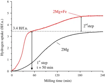
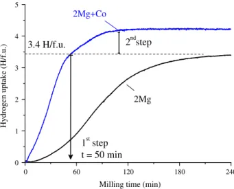
The reaction path during RMM synthesis (p(H2) = 7.5 MPa for 12 h) of Mg2FeH6has been recently
studied in an Evico-magnetics vial[116]. The evolution of the hydrogen uptake as a function of milling
time is shown inFig. 11. The result for a similar experiment using only Mg powder is shown in the
same figure for comparison. Hydrogen absorption by 2Mg + Fe powder mixture occurs in two steps.
0 1 2 3 4 5 6 2ndstep
Hydrogen uptake (H/f.u.)
Milling time (min)
2Mg
1st step t = 50 min 3.4 H/f.u.2Mg+Fe
0 60 120 180 240Fig. 11.Time-evolution of the H concentration in solid-state during RMM of Mg powder and 2Mg + Fe powder mixture.
Fig. 12.XRD patterns and phase identification of RMM 2Mg + Fe powder mixture after the first (50 min) and the second
The first step, witht< 50 min, corresponds to the formation of MgH2hydride as demonstrated by both
the equivalent amount of absorbed hydrogen in the experiment conducted with elemental Mg andex
situXRD measurements (Fig. 12). The second step corresponds to the reaction between MgH2and Fe to
form Mg2FeH6. The XRD pattern for 12 h milled product (Fig. 12) shows the presence of three phases
Mg2FeH6(77 wt%), Fe (12 wt%) and MgO (11 wt%) with crystallite sizes of 8, 12 and 4 nm, respectively.
In contrast to previous reports no amorphization is observed on prolonged milling[115,143]. MgO
contamination is attributed to undesired surface oxidation of fine Mg powder (36
l
m) in glove-boxand accounts for unreacted Fe residual[144]. According to these results, the two-step reaction path
for Mg2FeH6synthesis could be described as:
2MgðsÞ þFeðsÞ þ3H2ðgÞ !2MgH2ðsÞ þFeðsÞ þH2ðgÞ !Mg2FeH6ðsÞ ð2Þ
It is worth noting that reaction kinetics for the first step, i.e. MgH2formation, is faster for the 2Mg + Fe
mixture than for pure Mg powder. This striking result may be related either to catalytic effects for
hydrogen dissociation at the Fe surface or to nucleation phenomena at Mg/Fe interfaces[145].
The reaction path given by Eq.(2)concurs with recent reports on hydrogen absorption by classical
solid–gas reaction in nanosized Mg + Fe mixtures[146,147]. Based on DFT calculations, it has been
proposed that the reaction between iron and magnesium hydride may occur through the formation
of a (MgFe)H2 solid solution which becomes unstable with increasing Fe content with respect to
Mg2FeH6[148].
As we saw in the previous sections, ball milling has been extensively used to synthesize Mg2FeH6.
In the case of Severe Plastic Deformation SPD techniques, investigation has only started recently and the literature is much less abundant. Lima et al. observed substantial improvement in the hydrogen
sorption kinetics of a Mg–Fe powder mixture processed by high pressure torsion HPT[16]. The authors
noted that hydrogenation and dehydrogenation of the processed samples did not change the prefer-ential orientation (0 0 2) of the Mg phase, i.e. the material retained the microstructure imposed by HPT. In a subsequent investigation, the same authors used a combination of ball milling and extrusion
to synthesize Mg2FeH6[149]. Their results indicate that the iron in the 2Mg–Fe mixture produced a
beneficial pinning effect on the Mg grains by hindering grain coarsening even after annealing treat-ments. The desorption kinetics of samples processed by high pressure torsion (HPT) was faster than
that of extruded samples, probably due to bulk diffusion limitations[149].
3.3.2. Mg2Co hydride
Similarly to Mg2FeH6, first attempts to produce Mg2CoH5by RMM (p(H2) = 1 MPa for 20 h) of Mg
and Co powder were unsuccessful. Instead, a mixture of MgH2and Co phases was obtained[133].
Subsequent sintering treatment allowed synthesizing Mg2CoH5hydride though with a lower yield
(26 wt%) than for Mg2FeH6(65 wt%).
The synthesis of Mg2CoH5hydride by RMM (p(H2) = 0.1 MPa for 10 h) of MgH2and Co powders in
molar ration 2:1 under hydrogen pressure was first reported by Chen et al.[48].Ex situXRD
measure-ments revealed that Mg2CoH5phase started forming at 1 h milling and became the major phase after
10 h milling. Later, the synthesis could be also achieved using Mg and Co powders as reactants under
0.5 MPa of hydrogen[135]. The powders were previously milled under Ar atmosphere in the same
sys-tem for 200 h. It was supposed that intimate contact and homogeneity between Mg and Co phases is
essential to reach hydride formation as occurring for sintering methods[150]. The Mg2CoH5phase
starts forming after 40 h of milling and a yield of 50 wt% was achieved at 90 h. The formation of an
intermediate MgH2phase occurs from 10 h of milling. The two-step reaction has been also observed
by Baum et al. byin situmonitoring of hydrogen uptake during RMM experiments[51].
The reaction path during RMM synthesis (p(H2) = 7.5 MPa for 12 h) of Mg2CoH5from Fe and Co
powders in molar ratio 2:1 has been recently studied in detail[116]. The evolution of the hydrogen
uptake as a function of milling time is shown inFig. 13. Hydrogen absorption occurs in two steps
which, after the analysis of XRD data (Fig. 14), correspond to the following reactions:
2MgðsÞ þCoðsÞ þ5=2H2ðgÞ !2MgH2ðsÞ þCoðsÞ þ1=2H2ðgÞ !Mg2CoH5ðsÞ ð3Þ
MgH2hydride is formed as an intermediate phase fort< 50 min. The reaction is again faster as
Mg2CoH5. The hydrogen uptake corresponding to this reaction is lower but faster than for Mg2FeH6
formation (Fig. 11). The XRD pattern for 12 h milled product (Fig. 14) shows the formation of
nano-crystalline (8 nm) Mg2CoH5phase without significant amorphous contribution.
3.3.3. Mg2Ni hydride
Since Mg2Ni compound exists as stable phase in the binary Mg–Ni phase diagram, the synthesis of
Mg2NiH4 ternary hydride by RMM can be attempted either using 2Mg + Ni elemental mixture or
Mg2Ni powders as initial reactants.
This synthesis was first tried by RMM (p(H2) = 0.5 MPa for 22 h) of 2Mg + Ni powders[29]. Some
MgH2phase was formed from 2 h of milling but no ternary hydride could be detected. Either milling
energy (ball-to-powder weight ratio was 4:1 and milling speed 325 rpm) or hydrogen supply was insufficient to promote hydride formation.
Orimo et al. later investigated hydrogen absorption in Mg2Ni during reactive milling (p(H2) = 1 MPa
for 80 h) using stronger energetic conditions: rotation speed of 400 rpm and ball-to-powder weight
Fig. 14.XRD patterns and phase identification of RMM 2Mg + Co powder mixture after the first (50 min) and the second
(720 min) reaction step (Cu Karadiation).
0 1 2 3 4 5
3.4 H/f.u.
2
ndstep
2Mg+Co
Hydrogen uptake (H/f.u.)
2Mg
1
ststep
t = 50 min
Milling time (min)
0 60 120 180 240
ratio 30:1[136]. Instead of ternary hydride formation, a gradual solid solution of hydrogen in the
Mg2Ni powder with a maximum hydrogen content of 1.8 H/f.u. after 80 h is reported. The position
of XRD diffraction lines does not depend however on the hydrogen content. The milled material has
a two-phase microstructure formed by nanocrystalline (15 nm) Mg2Ni regions with low H-content
(0.3 H/f.u.) and disordered intergrain regions that store high amounts of hydrogen. Such a particular
microstructure has not later been confirmed by other research groups.
Tessier et al. also performed RMM experiments using Mg2Ni powder as starting reactant. RMM
experiments (p(H2) = 1.0 MPa for 10 h) were performed in a Kurimoto planetary mill at a high rotation
speed of 885 rpm[137]. Contrary to Orimo et al., the formation of disordered intergrain regions with
high H-content is not observed. The synthesis of70 wt% of Mg2NiH4ternary hydride, as estimated
from total hydrogen content in the milled product, is detected. The hydride crystallizes as a mixture
of low- and high-temperature phases of Mg2NiH4hydride[151,152]. The high temperature
modifica-tion is usually formed above 510 K but it seems to be stabilized by mechanical milling[153].
Baum et al. have monitored thein situhydrogen uptake during RMM of 2Mg + Ni elemental powder
mixture with identical milling parameters as mentioned above for the synthesis of Mg2FeH6[51].
Suc-cessful formation of Mg2NiH4ternary hydride is reported after 16 h of milling. The hydrogen uptake
curve exhibits a unique step. This result differs from experiments on Mg2FeH6and Mg2CoH5formation
and was tentatively attributed to a simpler process for Mg2NiH4related to the existence of Mg2Ni
compound. However, this seems not to be the case.Fig. 15displays thein situhydrogenation curves
monitored during the synthesis of Mg2NiH4 hydride [116]. Indeed, one-hydrogenation step for
t< 50 min is observed. As proved by XRD diffraction studies of the sample milled for this time (top
pattern inFig. 16), the reaction is however not completed since a high amount of the starting Ni
pow-der remains unreacted. Further milling for 12 h leads to complete formation of Mg2NiH4hydride as
shown by the XRD pattern displayed in bottomFig. 16. This second step on the formation of the
ter-nary hydride is a solid–solid state reaction, i.e. it occurs without any hydrogen absorption. The
reac-tion path of Mg2NiH4formation is then described according to reaction scheme:
2MgðsÞ þNiðsÞ þ2H2ðgÞ !2MgH2ðsÞ þNiðsÞ !Mg2NiH4ðsÞ ð4Þ
According to this reaction and to the previous experiments reported by Baum et al.[51]and Zhang
et al.[116], the synthesis of all Mg-based Mg2THxternary hydrides (T= Fe, Co and Ni) by RMM of
ele-mental pure powders under hydrogen atmosphere occurs through a common reaction path: 2MgðsÞ þTðsÞ þx
2H2ðgÞ !2MgH2ðsÞ þTðsÞ þ
ðx4Þ
2 H2ðgÞ !Mg2THxðsÞ ð5Þ
withx= 6, 5 and 4 forT= Fe, Co and Ni, respectively.
0 1 2 3 4 3.4 H/f.u.
2Mg+Ni
Hydrogen uptake (H/f.u.)
2Mg
1st step t = 50 min
Milling time (min)
0 60 120 180 240
Baum et al. have also reported the possibility of synthesizing quaternary Mg2T0.5T’0.5Hxhydrides
withT,T’ = Fe, Co and Ni[51]. This result has been confirmed by Deledda and Hauback forT= Fe
andT’ = Co[52]. The later authors obtained a quaternary hydride of composition Mg2(FeH6)0.5(CoH5)0.5
in which both [FeH6]4and [CoH5]4and complex anions coexist in the same compound. The
synthe-sized compound desorbed hydrogen in a one-step reaction at temperatures between 500 and 600 K
which is between those of Mg2FeH6and Mg2CoH5. These results open up the possibility of
synthesiz-ing other Mg-based transition–metal complex hydrides, in which the hydrogen storage properties can be tailored by varying the transition metals and the relative content of the complex anion.
3.4. Alanates
Since the pioneering work of Bogdanovic´ and Schwickardi, who found that Ti-catalyzed NaAlH4can
release hydrogen under moderate conditions, the potential interest of metal aluminum complex
hy-drides, also known as alanates, for reversible hydrogen storage remains vivid [154]. Alanates are
formed by anionic aluminum–hydrogen complexes (typically either [AlH4]or [AlH6]3) stabilized
by a cation (typically an alkali or alkaline earth metal)[2,155]. Their gravimetric (up to 10.8 wt%
though only 5.6 wt% reversible) and volumetric capacities (90 g/L) make these compounds attractive
for hydrogen storage.
Conventionally, alanates are prepared by a wet chemical route. For instance, to synthesize sodium alanate, NaH and Al are diluted in THF and hydrogen pressure up to 20 MPa at 423 K is applied for few
days. Subsequently, the NaAlH4in solution is filtered and dried. Since the solubility of NaAlH4is very
low, a high amount of solvent is necessary. Dymova et al. have shown that the synthesis of NaAlH4can
also be obtained from Na, Al and H2at high temperature (553 K), where Na is in liquid state, and high
hydrogen pressure (17.5 MPa)[156].
In 1999, mechanochemical synthesis methods started being employed to synthesize Na3AlH6and
Na2LiAlH6complex hydrides using NaAlH4and LiAlH4as reagents[157,158]. Very recently, it has been
shown that NaAlH4can be formed by milling NaH and Al under a hydrogen atmosphere of 8.3 MPa,
4 mol% of TiCl3was added as a dopant[30]. The alanates synthesized by reactive mechanical milling
are surveyed hereafter (Table 3).
3.4.1. Lithium alanates
The synthesis of LiAlH4and Li3AlH6has been attempted by Kojima et al. under 1 MPa of hydrogen
using a planetary ball mill at 400 rpm[165]. After 24 h of milling with addition of TiCl3, the XRD
pat-tern shows broad peaks of LiH and Al phases but no clear signature of alanate formation. However, the
Raman and27Al MAS NMR spectra indicate that a small amount of LiAlH
4was formed. Actually,
lith-ium alanate LiAlH4is metastable and it is considered as a non-reversible hydrogen storage compound
Fig. 16.XRD patterns and phase identification of RMM 2Mg + Ni powder mixture after the first (50 min) and after 720 min of
under moderate temperature and pressure conditions[166,167]. Indeed, the desorption of hydrogen
from LiAlH4is reported to be an exothermic process[161]. Lithium alanate does not form directly from
LiH, Al and H2by solid–gas reaction. It is classically produced by using liquid complexing agents
fol-lowed by desolvatation[168,169].
3.4.2. Sodium alanates
The sodium tetra-alanate NaAlH4is the best performing and most studied among all the alanates.
Bellosta von Colbe et al. have synthesized NaAlH4by RMM (p(H2) = 8.3 MPa for 4 h) of NaH and Al
powders using 4 mol% TiCl3as a dopant[30]. The obtained alanate exhibits a reversible capacity of
4 wt% and very fast kinetics without activation. In the same year, Wang et al. also tried the synthesis
of NaAlH4by the same means but at a lower pressure of 0.85 MPa and using TiF3as a dopant[160].
Within the first 5 h of milling, alanate formation was not observed. However, further milling up to
20 h led to partial synthesis of the more stable Na3AlH6phase.
Eigen et al. have also tried the synthesis of NaAlH4at moderate hydrogen pressures (from 0.6 to
1.2 MPa)[53]. NaAlH4could be formed with and without the addition of TiCl4as catalyst. However,
a long milling time (100 h without TiCl4, 20 h with TiCl4) is needed to obtain a small fraction of NaAlH4
under 0.6 MPa of hydrogen. Generated heat due to material plastic deformation and the friction
be-tween the milling balls and vial wall during milling could lead to a temperature at which the NaAlH4
is not stable at the imposed hydrogen pressure. A complete formation of NaAlH4could be achieved by
reducing the milling energy (ball-to-powder weight ratio and rotational speed were decreased from 50:1 and 350 rpm to 10:1 and 230 rpm) and increasing the hydrogen pressure (1.2 MPa).
Xiao et al. have also actively worked on the synthesis of NaAlH4by RMM under hydrogen pressure
of 0.5–3 MPa [159]. They observed that while Na3AlH6 forms under 0.5 MPa hydrogen pressure,
NaAlH4only forms above 0.8 MPa[159]. These results are similar to those of Eigen et al. and prove that
the formation of NaAlH4needs a minimum hydrogen pressure about 1 MPa, which is much higher
than the equilibrium pressure of NaAlH4at room temperature (about 0.1 MPa)[53]. This is attributed
to temperature rising on milling. By increasing the hydrogen pressure to 3 MPa, the synthesis yield of
NaAlH4reached 87 wt% after milling for 60 h.
Table 3
Alanates synthesised by RMM under hydrogen gas. The employed device, reactants, initial hydrogen pressure,p(H2), total milling
time (tmt), milling speed (ms), ball-to-powder weight ratio (BTPWR), ball diameter (Bd), reaction yield and formed side products are given.
Compound Device Reactants p(H2)
(MPa) tmt (h) ms (rpm) BTPWR Bd (mm) Yield (wt%)
Side products Ref
NaAlH4 Fritsch P7 NaH + Al 8.3 4 500 50:1 NaCl, Al [30]
NaAlH4 Fritsch P5 NaH + Al 0.6 120 350 50:1 10 Low Na3AlH6, NaH,
Al
[53]
NaAlH4 Fritsch P5 NaH + Al 1.2 240 230 10:1 10 High NaCl, Al [53]
NaAlH4 Planetary NaH + Al 3 60 350 30:1 8 86 Na3AlH6, Al [159]
Na3AlH6 Fritsch P6 NaH + Al 0.85 20 400 40:1 Al [160]
Na3AlH6 Planetary NaH + Al 0.5 30 350 30:1 8 58 Al [159]
Na3AlH6 Fritsch
P4a
3NaH + Al 10 8 400 90:1 15 92 NaCl, NaH, Al [57]
KAlH4 Fritsch P7 KH + Al 10 10 400 [161]
Na2LiAlH6 Fritsch
P4a
LiH + 2NaH + Al 10 4 400 90:1 15 97 NaCl [57]
K2NaAlH6 Fritsch
P4a
2KH + NaH + Al 10 2 400 90:1 15 98 NaH [57]
Mg(AlH4)2 Fritsch P7 2AlH3+ MgH2 0.1 4 400 175:1 10 81 AlH3, MgH2, Al [162]
Ca(AlH4)2 Fritsch P6 2AlH3+ CaH2 0.1 10 500 13 [163]
CaAlH5 Fritsch P7 AlH3+ CaH2 0.1 3 400 80:1 10 91 CaH2, Al [162]
Ba2AlH7 Fritsch P5 BaH2+ Al 0.8 10 300 40:1 84 BaH2, Al [164]
BaAlH5 Fritsch P5 BaH2+ 2Al 0.8 10 300 40:1 83 Al [164]
a
![Fig. 1. X-ray powder diffraction pattern of arc-melted TiV 0.9 Mn 1.1 as a function of milling time (Cu K a radiation) [77].](https://thumb-us.123doks.com/thumbv2/123dok_us/9821638.2474557/4.701.183.522.634.917/fig-powder-diffraction-pattern-melted-function-milling-radiation.webp)
![Fig. 2. Pressure–composition temperature (PCT) curve, at 313 K, of arc-melted TiV 0.9 Mn 1.1 alloy before and after 80 h of milling [77].](https://thumb-us.123doks.com/thumbv2/123dok_us/9821638.2474557/5.701.166.523.633.903/fig-pressure-composition-temperature-curve-melted-alloy-milling.webp)
![Fig. 5. The powder X-ray diffraction pattern of a magnesium titanium Mg 50 Ti 50 mixture milled for 150 h (Cu K a radiation) [84].](https://thumb-us.123doks.com/thumbv2/123dok_us/9821638.2474557/8.701.186.525.91.282/powder-diffraction-pattern-magnesium-titanium-mixture-milled-radiation.webp)
![Fig. 7. Evolution of the pressure and temperature (A) during RMM of magnesium in hydrogen gas and the calculated H/Mg ratio in the solid state (B) as a function of time [64].](https://thumb-us.123doks.com/thumbv2/123dok_us/9821638.2474557/12.701.87.617.721.903/evolution-pressure-temperature-magnesium-hydrogen-calculated-ratio-function.webp)