University of Wollongong
University of Wollongong
Research Online
Research Online
Faculty of Engineering and Information
Sciences - Papers: Part B
Faculty of Engineering and Information
Sciences
2019
Microstructure Evolution during the Production of Dual Phase and
Microstructure Evolution during the Production of Dual Phase and
Transformation Induced Plasticity Steels Using Modified Strip
Transformation Induced Plasticity Steels Using Modified Strip
Casting Simulated in the Laboratory
Casting Simulated in the Laboratory
Zhiping Xiong
University of Science And Technology Beijing, [email protected]
Andrii Kostryzhev
University of Wollongong, [email protected]
Yanjun Zhao
Guangxi University
Elena V. Pereloma
University of Wollongong, [email protected]
Follow this and additional works at: https://ro.uow.edu.au/eispapers1
Recommended Citation
Recommended Citation
Xiong, Zhiping; Kostryzhev, Andrii; Zhao, Yanjun; and Pereloma, Elena V., "Microstructure Evolution during the Production of Dual Phase and Transformation Induced Plasticity Steels Using Modified Strip Casting Simulated in the Laboratory" (2019). Faculty of Engineering and Information Sciences - Papers: Part B. 2757.
https://ro.uow.edu.au/eispapers1/2757
Research Online is the open access institutional repository for the University of Wollongong. For further information contact the UOW Library: [email protected]
Microstructure Evolution during the Production of Dual Phase and
Microstructure Evolution during the Production of Dual Phase and
Transformation Induced Plasticity Steels Using Modified Strip Casting Simulated
Transformation Induced Plasticity Steels Using Modified Strip Casting Simulated
in the Laboratory
in the Laboratory
Abstract
Abstract
Instead of conventional steel making and continuous casting followed by hot and cold rolling, strip casting technology modified with the addition of a continuous annealing stage (namely, modified strip casting) is a promising short-route for producing ferrite-martensite dual-phase (DP) and multi-phase transformation-induced plasticity (TRIP) steels. However, at present, the multi-phase steels are not manufactured by the modified strip casting, due to insufficient knowledge about phase transformations occurring during in-line heat treatment. This study analysed the phase transformations, particularly the formation of ferrite, bainite and martensite and the retention of austenite, in one
0.17C-1.52Si-1.61Mn-0.195Cr (wt. %) steel subjected to the modified strip casting simulated in the laboratory. Through the adjustment of temperature and holding time, the characteristic microstructures for DP and TRIP steels have been obtained. The DP steel showed comparable tensile properties with industrial DP 590 and the TRIP steel had a lower strength but a higher ductility than those industrially produced TRIP steels. The strength could be further enhanced by the application of deformation and/or the addition of alloying elements. This study indicates that the modified strip casting technology is a promising new route to produce steels with multi-phase microstructures in the future.
Publication Details
Publication Details
Xiong, Z., Kostryzhev, A. G., Zhao, Y. & Pereloma, E. V. (2019). Microstructure Evolution during the Production of Dual Phase and Transformation Induced Plasticity Steels Using Modified Strip Casting Simulated in the Laboratory. Metals, 9 (4), 449-1-449-14.
metals
ArticleMicrostructure Evolution During the Production of
Dual Phase and Transformation Induced Plasticity
Steels Using Modified Strip Casting Simulated in
the Laboratory
Zhiping Xiong1,2 , Andrii G. Kostryzhev2, Yanjun Zhao1,* and Elena V. Pereloma2,3
1 Guangxi Key Laboratory of Processing for Non-ferrous Metal and Featured Materials, Guangxi University,
Nanning 530004, China; [email protected]
2 School of Mechanical, Materials, Mechatronic and Biomedical Engineering, University of Wollongong,
Wollongong NSW 2522, Australia; [email protected] (A.G.K.); [email protected] (E.V.P.)
3 Electron Microscopy Centre, University of Wollongong, Wollongong NSW 2519, Australia
* Correspondence: [email protected]
Received: 16 February 2019; Accepted: 10 April 2019; Published: 16 April 2019
Abstract: Instead of conventional steel making and continuous casting followed by hot and cold rolling, strip casting technology modified with the addition of a continuous annealing stage (namely, modified strip casting) is a promising short-route for producing ferrite-martensite dual-phase (DP) and multi-phase transformation-induced plasticity (TRIP) steels. However, at present, the multi-phase steels are not manufactured by the modified strip casting, due to insufficient knowledge about phase transformations occurring during in-line heat treatment. This study analysed the phase transformations, particularly the formation of ferrite, bainite and martensite and the retention of austenite, in one 0.17C-1.52Si-1.61Mn-0.195Cr (wt. %) steel subjected to the modified strip casting simulated in the laboratory. Through the adjustment of temperature and holding time, the characteristic microstructures for DP and TRIP steels have been obtained. The DP steel showed comparable tensile properties with industrial DP 590 and the TRIP steel had a lower strength but a higher ductility than those industrially produced TRIP steels. The strength could be further enhanced by the application of deformation and/or the addition of alloying elements. This study indicates that the modified strip casting technology is a promising new route to produce steels with multi-phase microstructures in the future.
Keywords: strip casting; heat treatment; DP steel; TRIP steel; phase transformation
1. Introduction
The strip casting technology allows to produce solid metal strips from liquid metals with minimal amount of deformation in one hot rolling stand continuously operating with a casting unite [1]. This technique has been applied in industry for the production of aluminium, lead, carbon steel, silicon steel and stainless steel [2–4]. In laboratory the ferrite-martensite dual-phase (DP) steel [5–7], multi-phase transformation-induced plasticity (TRIP) steel [8,9] and twinning-induced plasticity steel [10] have also been successfully produced by strip casting. In comparison with a traditional way to produce steels by the sequence of steel-making, continuous casting, hot rolling and cold rolling, the strip casting technology requires a shorter production line, due to the strips being directly manufactured from liquid metals. Therefore, it is an efficient way to save energy, reduce CO2emission and increase profitability of a metallurgical enterprise with a minimal impact on environment [1,11].
Metals2019,9, 449 2 of 14
Typical DP steels contain soft ferrite and hard martensite and they are manufactured in industry by hot or cold rolling followed by annealing [12]. The presence of martensite leads to a continuous yielding behaviour and a moderate work hardening capability [12,13]. Strength and ductility can be adjusted via controlling the volume fraction of martensite. An increasing martensite fraction decreases the ductility but increases strength [14]. For example, when the martensite fraction is 40%, the ultimate tensile strength (UTS) is 660 MPa with a total elongation (TE) of 46.7%; when the martensite fraction is 50%, the UTS is 670 MPa while the TE is 45.0% [14]. After cold rolling, the inter critical annealing in the ferrite-austenite two-phase region can control the ferrite fraction and the austenite fraction. During cooling to room temperature, the austenite will transform to martensite. Thus, the martensite fraction can be controlled through the adjustment of annealing temperature and time. A higher inter critical annealing temperature and longer holding time lead to a larger austenite fraction followed by a larger fraction of martensite after cooling to room temperature [13,14].
Multi-phase TRIP steels consist of ferrite, bainitic ferrite, granular bainite and retained austenite (RA); sometimes a small amount of martensite may be present [15–17]. These steels attract attention of many investigators and researchers all over the word because of their combination of high strength and good ductility. The reason for TRIP steels have a good balance between strength and ductility originates from the presence of RA grains. During deformation, the RA grains transform to martensite (namely, the TRIP effect) leading to enhanced ductility prior to fracture. This transformation in homogeneously occurs in a range of strain levels. Strains required to initiate the austenite-to-martensite transformation vary with the austenite stability ascribed to the austenite grain morphology, carbon content and type of neighbouring phases [17–19]. The TRIP effect delays the development of the local stress concentration and enhances the strain hardening ability, which results in an increased ductility [17,20,21]. Thus, the control of amount and stability of RA grains is a key factor for the enhancement of mechanical properties in TRIP steels [22,23]. The first stage of heat treatment schedule applied to obtain a TRIP steel microstructure is the inter critical annealing in the ferrite-austenite two-phase region. The temperature and holding time in the two-phase region can control the fraction and grain size of ferrite [15,24]. The second stage of heat treatment induces the bainite transformation, during which austenite is enriched in carbon, partitioning from bainite. The fraction, morphology and stability of RA grains can be controlled by adjusting the bainite transformation temperature, which affects the amount and morphology of bainite [16,20,25]. Bainitic ferrite comprises film RA clamped between bainitic ferrite laths, while granular bainite includes blocky RA surrounded by the irregular-shaped ferrite [17]. During the final cooling to room temperature, the austenite which is stable enough can be retained, while the unstable austenite transforms to martensite.
DP and TRIP steels are industrially produced by hot rolling or cold rolling followed by annealing [26]. In the automotive industry they have been successfully applied to manufacture various car parts such as B-pillar reinforcements, longitudinal beams and cross members [27]. Recent studies carried out by the present authors produced low-alloyed ferrite-martensite DP [8] and multi-phase TRIP steels [8] using strip casting simulated in the laboratory. Although tensile properties comparable with industrially hot/cold rolled DP and TRIP steels have been achieved, the microstructure is not uniform through strip thickness, due to the cooling rate gradient [8,9]. To avoid this problem, a furnace was introduced into the processing line of strip casting (Figure1) for the first time in this work, namely the modified strip casting. An interrupted cooling in the first zone of the furnace should result in formation of a ferrite-pearlite microstructure, instead of bainite and/or martensite obtained in the conventional strip casting due to fast cooling. This stage requires further researches on the acceleration of pearlite formation in the future in order to shorten the furnace in industry. Following this, the second step of heat treatment allowed to produce the homogeneous microstructures of DP and TRIP steels. The phase transformations occurring during the simulated heat treatments for the modified strip casting technology have been investigated and presented below (Figure1).
Metals2019,9, 449 3 of 14
Metals 2019, 8, x FOR PEER REVIEW 3 of 14
Figure 1. A schematic presentation of the modified strip casting.
2. Materials and Experimental Procedures
2.1. Materials
The received plates of 36 × 36 × 1.2 mm3 were cast using a dip tester (in‐house manufactured at
the University of Deakin, Victoria, Australia), which can simulate rapid solidification during strip
casting [28]. Thus, the features of the microstructure in the strip casting can be simulated in the
laboratory [5,8]. The technical parameters of dip tester can be found in Ref. [28]. The steel studied in
this work (contained 0.172) C, 1.520Si, 1.610Mn, 0.195Cr (wt. %) and balanced Fe. The cast
microstructure consisted of martensite and bainite as shown in Figure 2.
Figure 2. As‐cast microstructure consisting of martensite and bainite observed by scanning electron
microscopy (SEM).
2.2. Processing Schedules
The processing routes to obtain DP and TRIP steels are illustrated in Figure 3a,b, respectively.
They include two steps of heat treatments in order to simulate the modified strip casting in the
laboratory: (1) the first step of heat treatment is to produce a ferrite‐pearlite microstructure and (2)
the second step of heat treatment is to produce microstructures of DP and TRIP steels. The heat
treatment was carried out using a Theta Dilatronic III dilatometer (Theta Inc., New York, NY, USA)
under a vacuum of ~6.7 × 10⁻² Pa. Flat samples of 14 × 6 × 1 mm3 size were cut using wire cutting. To simulate the modified strip casting, the samples were heated at 30 Ks−1 to 1250 °C and held for 300 s and this led to an average grain size of prior austenite (80 ± 27 μm) being similar to that which is
usually observed in the strip casting [8]. After holding, the samples were rapidly cooled at ~90 Ks−1 to different holding temperatures (TF), held for different times (tF) to study the ferrite and pearlite
transformation during the modified strip casting and helium quenched at ~140 Ks−1 to room
temperature. To simulate the production of DP steels, the samples with a ferrite‐pearlite
microstructure were heated at 30 Ks−1 to a selected temperature of TIA (750 and 780 °C) in the two‐
phase region, held for a selected time period of tIA (120, 180, 240 and 300 s) to allow formation of a Figure 1.A schematic presentation of the modified strip casting.
2. Materials and Experimental Procedures 2.1. Materials
The received plates of 36×36×1.2 mm3were cast using a dip tester (in-house manufactured at the University of Deakin, Victoria, Australia), which can simulate rapid solidification during strip casting [28]. Thus, the features of the microstructure in the strip casting can be simulated in the laboratory [5,8]. The technical parameters of dip tester can be found in Ref. [28]. The steel studied in this work (contained 0.172) C, 1.520Si, 1.610Mn, 0.195Cr (wt. %) and balanced Fe. The cast microstructure consisted of martensite and bainite as shown in Figure2.
Metals 2019, 8, x FOR PEER REVIEW 3 of 14
Figure 1. A schematic presentation of the modified strip casting.
2. Materials and Experimental Procedures
2.1. Materials
The received plates of 36 × 36 × 1.2 mm3 were cast using a dip tester (in‐house manufactured at
the University of Deakin, Victoria, Australia), which can simulate rapid solidification during strip
casting [28]. Thus, the features of the microstructure in the strip casting can be simulated in the
laboratory [5,8]. The technical parameters of dip tester can be found in Ref. [28]. The steel studied in
this work (contained 0.172) C, 1.520Si, 1.610Mn, 0.195Cr (wt. %) and balanced Fe. The cast
microstructure consisted of martensite and bainite as shown in Figure 2.
Figure 2. As‐cast microstructure consisting of martensite and bainite observed by scanning electron
microscopy (SEM).
2.2. Processing Schedules
The processing routes to obtain DP and TRIP steels are illustrated in Figure 3a,b, respectively.
They include two steps of heat treatments in order to simulate the modified strip casting in the
laboratory: (1) the first step of heat treatment is to produce a ferrite‐pearlite microstructure and (2)
the second step of heat treatment is to produce microstructures of DP and TRIP steels. The heat
treatment was carried out using a Theta Dilatronic III dilatometer (Theta Inc., New York, NY, USA)
under a vacuum of ~6.7 × 10⁻² Pa. Flat samples of 14 × 6 × 1 mm3 size were cut using wire cutting. To simulate the modified strip casting, the samples were heated at 30 Ks−1 to 1250 °C and held for 300 s and this led to an average grain size of prior austenite (80 ± 27 μm) being similar to that which is
usually observed in the strip casting [8]. After holding, the samples were rapidly cooled at ~90 Ks−1 to different holding temperatures (TF), held for different times (tF) to study the ferrite and pearlite
transformation during the modified strip casting and helium quenched at ~140 Ks−1 to room
temperature. To simulate the production of DP steels, the samples with a ferrite‐pearlite
microstructure were heated at 30 Ks−1 to a selected temperature of TIA (750 and 780 °C) in the two‐
phase region, held for a selected time period of tIA (120, 180, 240 and 300 s) to allow formation of a Figure 2.As-cast microstructure consisting of martensite and bainite observed by scanning electron microscopy (SEM).
2.2. Processing Schedules
The processing routes to obtain DP and TRIP steels are illustrated in Figure3a,b, respectively. They include two steps of heat treatments in order to simulate the modified strip casting in the laboratory: (1) the first step of heat treatment is to produce a ferrite-pearlite microstructure and (2) the second step of heat treatment is to produce microstructures of DP and TRIP steels. The heat treatment was carried out using a Theta Dilatronic III dilatometer (Theta Inc., New York, NY, USA) under a vacuum of ~6.7×10⁻²
Pa. Flat samples of 14×6×1 mm3size were cut using wire cutting. To simulate the modified strip casting, the samples were heated at 30 Ks−1to 1250◦C and held for 300 s and this led to an average grain size of prior austenite (80±27µm) being similar to that which is usually observed in the strip casting [8]. After holding, the samples were rapidly cooled at ~90 Ks−1to different holding temperatures (TF), held for different times (tF) to study the ferrite and pearlite transformation during
the modified strip casting and helium quenched at ~140 Ks−1to room temperature. To simulate the production of DP steels, the samples with a ferrite-pearlite microstructure were heated at 30 Ks−1to a selected temperature ofTIA(750 and 780
◦
C) in the two-phase region, held for a selected time period of tIA(120, 180, 240 and 300 s) to allow formation of a certain volume fraction of austenite and helium
Metals2019,9, 449 4 of 14
of TRIP steels, the samples with ferrite-pearlite microstructure were heated at 750◦C for 240 s, which resulted in formation of ~50% ferrite and ~50% austenite and then quickly cooled at ~50 Ks−1to the isothermal bainite transformation temperature ofTIBT(400, 450 and 500◦C), held at this temperature
for 900 s (15 min) to simulate coiling and finally helium quenched at ~140 Ks−1to room temperature.
Metals 2019, 8, x FOR PEER REVIEW 4 of 14
certain volume fraction of austenite and helium quenched to room temperature to obtain martensite
as the second phase. To simulate the production of TRIP steels, the samples with ferrite‐pearlite
microstructure were heated at 750 °C for 240 s, which resulted in formation of ~50% ferrite and ~50%
austenite and then quickly cooled at ~50 Ks−1 to the isothermal bainite transformation temperature of
TIBT (400, 450 and 500 °C), held at this temperature for 900 s (15 min) to simulate coiling and finally
helium quenched at ~140 Ks−1 to room temperature.
Figure 3. Schemes of processing schedules applied to simulate the production of (a) Dual Phase (DP)
and (b) Transformation‐Induced Plasticity (TRIP) steels using the modified strip casting.
2.3. Microstructure Characterization
The heat‐treated samples were cut through thickness, mounted, mechanically polished and
electropolished using an electrolyte containing 330 mL methanol, 330 mL butoxyethanol and 40 mL
perchloric acid. Then, the samples were etched using 2 vol % nital. The microstructures were
characterized using a Leica DMR research optical microscope (OM) (Leica, Wetzlar, Germany) and a
JEOL JSM‐7001F field emission gun scanning electron microscope (FEG SEM) (Jeol, Tokyo, Japan)
operating at an accelerating voltage of 15 kV. On the basis of the pixel quantities of different grey
scales in the micrographs, the ferrite fraction was calculated using ImageJ (Image‐Pro Plus, Media
Cybernetics Inc., Rockville, MD, USA). In order to distinguish between austenite, martensite and
bainite, colour etching was employed according to Ref. [28]. A PANalyticalX’pert‐Pro MRD
goniometer (Malvern Panalytical, Eindhoven, Netherlands), equipped with Ni‐filtered Cu Kα
radiation source scanning over a range of 2θ = 60–110°, was used to measure the RA fraction. The RA
fraction was calculated using the direct comparison method; the details are presented in Ref. [8].
2.4. Mechanical Properties
The dog‐bone tensile samples (with a gauge length of 4.9 mm, width of 2.1 mm and thickness of
1 mm) were cut from the heat‐treated samples. The uniaxial tensile testing was carried out using an
in‐house modified Kammrath and Weiss GmbH tensile stage (Kammrath & Weiss GmbH, Dortmund,
Germany) at a constant cross‐head speed of 2 μm/s, which resulted in an initial strain rate of 4 × 10‐4
s−1. 3. Results
3.1. The Formation of Ferrite and Pearlite Microstructure during the First Step of Simulated Heat
Treatments in the Modified Strip Casting
The microstructure evolution with holding temperature (TF) and time (tF) (Figure 3) is shown in
Figure 4 and the corresponding fractions of ferrite are listed in Table 1. Figure 3a was observed by
Figure 3.Schemes of processing schedules applied to simulate the production of (a) Dual Phase (DP) and (b) Transformation-Induced Plasticity (TRIP) steels using the modified strip casting.
2.3. Microstructure Characterization
The heat-treated samples were cut through thickness, mounted, mechanically polished and electropolished using an electrolyte containing 330 mL methanol, 330 mL butoxyethanol and 40 mL perchloric acid. Then, the samples were etched using 2 vol % nital. The microstructures were characterized using a Leica DMR research optical microscope (OM) (Leica, Wetzlar, Germany) and a JEOL JSM-7001F field emission gun scanning electron microscope (FEG SEM) (Jeol, Tokyo, Japan) operating at an accelerating voltage of 15 kV. On the basis of the pixel quantities of different grey scales in the micrographs, the ferrite fraction was calculated using ImageJ (Image-Pro Plus, Media Cybernetics Inc., Rockville, MD, USA). In order to distinguish between austenite, martensite and bainite, colour etching was employed according to Ref. [28]. A PANalyticalX’pert-Pro MRD goniometer (Malvern Panalytical, Eindhoven, Netherlands), equipped with Ni-filtered Cu Kαradiation source scanning
over a range of 2θ=60–110◦, was used to measure the RA fraction. The RA fraction was calculated using the direct comparison method; the details are presented in Ref. [8].
2.4. Mechanical Properties
The dog-bone tensile samples (with a gauge length of 4.9 mm, width of 2.1 mm and thickness of 1 mm) were cut from the heat-treated samples. The uniaxial tensile testing was carried out using an in-house modified Kammrath and Weiss GmbH tensile stage (Kammrath & Weiss GmbH, Dortmund, Germany) at a constant cross-head speed of 2µm/s, which resulted in an initial strain rate of 4×10⁻⁴s−1. 3. Results
3.1. The Formation of Ferrite and Pearlite Microstructure during the First Step of Simulated Heat Treatments in the Modified Strip Casting
The microstructure evolution with holding temperature (TF) and time (tF) (Figure3) is shown in
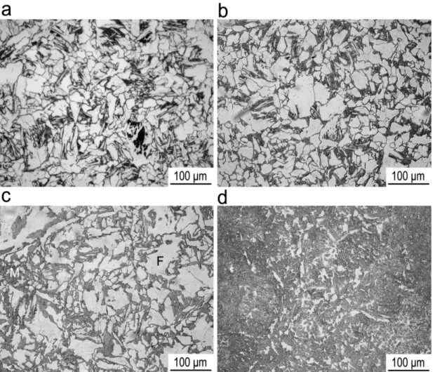
Figure4and the corresponding fractions of ferrite are listed in Table1. Figure3a was observed by OM where black is pearlite, white is ferrite and grey is martensite. Figure3b–f were obtained by SEM where dark grey is ferrite, light grey is martensite and white is pearlite. With an increase in holding temperature from 620 to 650◦C, for a constant holding time of 180 s, the fraction of ferrite increased
Metals2019,9, 449 5 of 14
from 0.14±0.02 to 0.46±0.02 (Figure4a,d,f) due to a shortened incubation time for ferrite nucleation and a correspondingly increased time for ferrite growth. With increasing the holding temperature up to 670◦C the fraction of ferrite decreased (as listed in Table1for the holding time of 60 or 300 s) due to an increased incubation time for ferrite nucleation. It means that the nose temperature (namely, having shortest incubation time for phase transformation) of ferrite transformation field of the continuous phase transformation diagram is 650◦C. When the holding temperature is 650◦C, the ferrite fraction increases with an increased holding time from 60 to 180 s (Table1) due to an increased time for ferrite nucleation and growth. When the holding time was 180 s, a minor fraction of pearlite was observed at 620◦C (Figure4a). A larger fraction of pearlite was obtained after holding at 630◦C (Figure4c,d)due to a shortened time for pearlite nucleation. Whereas, only little pearlite was observed at a higher temperature of 650◦C (Figure4e,f) due to an increased time for pearlite nucleation. Therefore, the nose temperature of pearlite transformation field was 630Metals 2019, 8, x FOR PEER REVIEW ◦C. 6 of 14
Figure 4. (a) Optical microscopy (OM) and (b–f) SEM microstructures after holding at (a) 620 °C for
180 s, (b) 670 °C for 300 s, (c,d) 630 °C for 180 s and (e,f) 650 °C for 180 s. F is ferrite, P is pearlite and M is martensite.
Table 1. The fraction of ferrite as a function of holding temperature and time.
Time 620 °C 630 °C 650 °C 670 °C
60 s ‐ ‐ 0.08 ± 0.02 0.02 ± 0.001
180 s 0.14 ± 0.02 0.33 ± 0.02 0.46 ± 0.02 ‐
300 s ‐ 0.46 ± 0.04 0.56 ± 0.02 0.50 ± 0.03
Since the nose temperatures of ferrite and pearlite transformation field were 650 and 630 °C,
respectively, the holding for ferrite and pearlite formation was conducted between these two
temperatures, namely 635 °C. This was supposed to enhance the austenite decomposition. Figure 5
shows that the corresponding microstructure consists of ferrite (0.75 ± 0.02) and pearlite. This
microstructure was suitable for further processing to produce DP and TRIP steels because ferrite is a
Figure 4.(a) Optical microscopy (OM) and (b–f) SEM microstructures after holding at (a) 620◦C for
180 s, (b) 670◦C for 300 s, (c,d) 630◦C for 180 s and (e,f) 650◦C for 180 s.Fis ferrite,Pis pearlite andM
Metals2019,9, 449 6 of 14
Table 1.The fraction of ferrite as a function of holding temperature and time.
Time 620◦C 630◦C 650◦C 670◦C
60 s - - 0.08±0.02 0.02±0.001
180 s 0.14±0.02 0.33±0.02 0.46±0.02
-300 s - 0.46±0.04 0.56±0.02 0.50±0.03
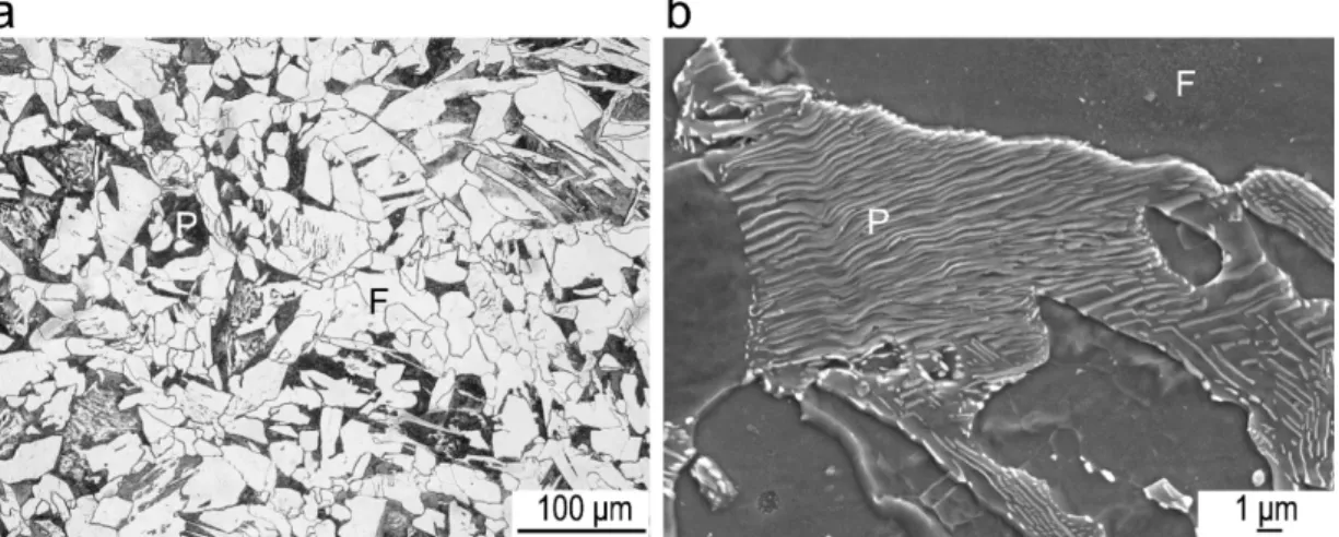
Since the nose temperatures of ferrite and pearlite transformation field were 650 and 630◦C, respectively, the holding for ferrite and pearlite formation was conducted between these two temperatures, namely 635 ◦C. This was supposed to enhance the austenite decomposition. Figure5shows that the corresponding microstructure consists of ferrite (0.75±0.02) and pearlite. This microstructure was suitable for further processing to produce DP and TRIP steels because ferrite is a microstructural constituent for both of them and austenite prefers to nucleate at the pearlite with a large driving force.
Metals 2019, 8, x FOR PEER REVIEW 7 of 14 microstructural constituent for both of them and austenite prefers to nucleate at the pearlite with a
large driving force.
Figure 5. Microstructures after austenitizing for 300 s at 1250 °C and holding at 635 °C for 900 s (15
min): (a) OM imaging and (b) SEM imaging. F is ferrite and P is pearlite.
3.2. Production of DP Steel Microstructure during the Second Step of Simulated Heat Treatments in the
Modified Strip Casting
Following the first step of simulated heat treatments in the modified strip casting in Section 3.1,
the second step of simulated heat treatments was investigated for the production of DP steels (Figure
3a). Figure 6 shows the microstructures after intercritical annealing at different temperatures for
different times within the two‐phase region followed by direct quenching to room temperature.
Quenching after the intercritical annealing led to the formation of microstructures consisting of ferrite
and martensite (Figure 6). When the intercritical annealing temperature was 750 °C, the ferrite
fraction decreased from 0.79 ± 0.01 to 0.42 ± 0.02 with the increase of the intercritical annealing time
from 120 to 300 s (Figure 7). When the intercritical annealing time was 300 s, a higher intercritical
annealing temperature of 780 °C led to a lower ferrite fraction of 0.09 ± 0.02 (Figure 6d).
With an increased intercritical annealing time in the austenite‐ferrite temperature region the
austenite grains continued to nucleate and grow and this resulted in a lower ferrite fraction (Figure
7). Similarly, a higher temperature led to a larger driving force for austenite formation resulting in a
less amount of ferrite. Thus, through the control of intercritical annealing temperature and time
during the intercritical annealing, DP steels having different fractions of ferrite and martensite can be
produced.
Figure 5.Microstructures after austenitizing for 300 s at 1250◦C and holding at 635◦C for 900 s (15 min): (a) OM imaging and (b) SEM imaging.Fis ferrite andPis pearlite.
3.2. Production of DP Steel Microstructure during the Second Step of Simulated Heat Treatments in the Modified Strip Casting
Following the first step of simulated heat treatments in the modified strip casting in Section3.1, the second step of simulated heat treatments was investigated for the production of DP steels (Figure3a). Figure6shows the microstructures after inter critical annealing at different temperatures for different times within the two-phase region followed by direct quenching to room temperature. Quenching after the inter critical annealing led to the formation of microstructures consisting of ferrite and martensite (Figure6). When the inter critical annealing temperature was 750◦
C, the ferrite fraction decreased from 0.79±0.01 to 0.42±0.02 with the increase of the inter critical annealing time from 120 to 300 s (Figure7). When the inter critical annealing time was 300 s, a higher inter critical annealing temperature of 780◦C led to a lower ferrite fraction of 0.09±0.02 (Figure6d).
With an increased inter critical annealing time in the austenite-ferrite temperature region the austenite grains continued to nucleate and grow and this resulted in a lower ferrite fraction (Figure7). Similarly, a higher temperature led to a larger driving force for austenite formation resulting in a less amount of ferrite. Thus, through the control of inter critical annealing temperature and time during the inter critical annealing, DP steels having different fractions of ferrite and martensite can be produced.
Metals2019,9, 449 7 of 14 Metals 2019, 8, x FOR PEER REVIEW 8 of 14
Figure 6. OM microstructures after intercritical annealing at (a) 750 °C for 120 s, (b) 750 °C for 180 s,
(c) 750 °C for 300 s and (d) 780 °C for 300 s. White is ferrite (F) while grey is martensite.
Figure 7. Effect of temperature and time on ferrite fraction during the intercritical annealing.
3.3. Production of TRIP Steel Microstructure during the Second Step of Simulated Heat Treatments in the
Modified Strip Casting
Following the first step of simulated heat treatments in the modified strip casting in Section 3.1,
the second step of simulated heat treatments has been investigated for the production of TRIP steels
(Figure 3b). Based on the published data, ~50% ferrite fraction provides the optimal combination of Figure 6.OM microstructures after inter critical annealing at (a) 750◦C for 120 s, (b) 750◦C for 180 s, (c) 750◦C for 300 s and (d) 780◦C for 300 s. White is ferrite (F) while grey is martensite.
Metals 2019, 8, x FOR PEER REVIEW 8 of 14
Figure
6.
OM
microstructures
after
intercritical
annealing
at
(
a
)
750
°C
for
120
s,
(
b
)
750
°C
for
180
s,
(
c
)
750
°C
for
300
s
and
(
d
)
780
°C
for
300
s.
White
is
ferrite
(
F
)
while
grey
is
martensite.
Figure
7.
Effect
of
temperature
and
time
on
ferrite
fraction
during
the
intercritical
annealing.
3.3.
Production
of
TRIP
Steel
Microstructure
during
the
Second
Step
of
Simulated
Heat
Treatments
in
the
Modified
Strip
Casting
Following
the
first
step
of
simulated
heat
treatments
in
the
modified
strip
casting
in
Section
3.1,
the
second
step
of
simulated
heat
treatments
has
been
investigated
for
the
production
of
TRIP
steels
(Figure
3b).
Based
on
the
published
data,
~50%
ferrite
fraction
provides
the
optimal
combination
of
Metals2019,9, 449 8 of 14
3.3. Production of TRIP Steel Microstructure during the Second Step of Simulated Heat Treatments in the Modified Strip Casting
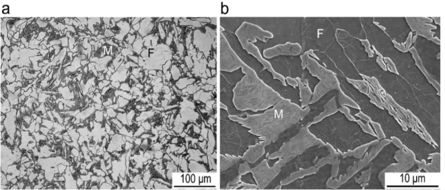
Following the first step of simulated heat treatments in the modified strip casting in Section3.1, the second step of simulated heat treatments has been investigated for the production of TRIP steels (Figure3b). Based on the published data, ~50% ferrite fraction provides the optimal combination of UTS and TE in the multi-phase TRIP steels [15,25]. According to Section3.2, 0.51±0.06 ferrite was achieved after inter critical annealing at 750◦C for 240 s (Figure8), this condition was selected for further processing to obtain bainite and RA required for TRIP steels.
Metals 2019, 8, x FOR PEER REVIEW 9 of 14 UTS and TE in the multi‐phase TRIP steels [15,25]. According to Section 3.2, 0.51 ± 0.06 ferrite was
achieved after intercritical annealing at 750 °C for 240 s (Figure 8), this condition was selected for
further processing to obtain bainite and RA required for TRIP steels.
Figure 8. Microstructures after intercritical annealing at 750 °C for 240 s followed by quenching to
room temperature: (a) OM imaging and (b) SEM imaging. F is ferrite and M is martensite.
The isothermal bainite transformation (IBT) was studied by holding at 400, 450 and 500 °C for
900 s (15 min). The representative and homogenous microstructures are shown in Figure 9 (OM) and
Figure 10 (SEM), indicating the successful production of typical TRIP steel microstructures [26].
Figure 9b,d,f show the ferrite in grey/white, bainite in dark grey/bluish, martensite in brown and RA
in grey/white. After holding at 400 °C, the microstructure consisted of ferrite, bainite, RA and
martensite (Figure 9a,b). As seen in Figure 10a, bainite included bainitic ferrite, where film‐shaped
retained austenite/martensite constituent (RA/M) was clamped by ferritic laths and granular bainite,
where globular RA/M was surrounded by irregular‐shaped ferrite. After holding at a higher
temperature of 450 °C the martensite fraction increased (Figures 9d and 10b). The increasing of
holding temperature up to 500 °C slightly decreased the martensite fraction (Figure 9f) and promoted
some pearlite formation (Figure 10c,d). It is well known that pearlite is harmful to the TRIP steels;
pearlite consumes carbon and reduces the carbon content in austenite. A decreased carbon content in
austenite decreases the austenite stability and the fraction of RA in the room temperature
microstructure [29,30]. Due to the presence of pearlite after holding at 500 °C this heat treatment
condition was regarded as inappropriate for the TRIP steel production and thus the RA fraction was
measured only for the samples held at 400 and 450 °C (Figure 11). Based on the direct comparison
method, the RA fraction was measured to be 5.2% and 4.2% after holding at 400 and 450 °C,
respectively.
The critical driving force (Gcritical) for bainite transformation can be expressed by the following
equation [31]:
𝐺 𝐴𝑇 𝐵 (1)
where A and B are positive constants related to the steel chemical compositions [32,33] and T is the
temperature. When the temperature decreased from ferrite‐austenite two‐phase region to bainite
transformation region, the bainite formed during the holding and the carbon diffused from bainitic
laths to austenite. Increasing the IBT temperature from 400 to 450 °C led to an increase in Gcritical. This
indicates that the transformation from austenite to bainite becomes more difficult with an increase in
temperature, leading to a lower fraction of bainite. For a lower fraction of bainite formation, the
content of carbon partitioning from bainitic ferrite laths into austenite was lower and thus the
austenite became less enriched in carbon. Therefore, a less stable austenite transformed to martensite
Figure 8.Microstructures after inter critical annealing at 750◦C for 240 s followed by quenching to room temperature: (a) OM imaging and (b) SEM imaging.Fis ferrite andMis martensite.
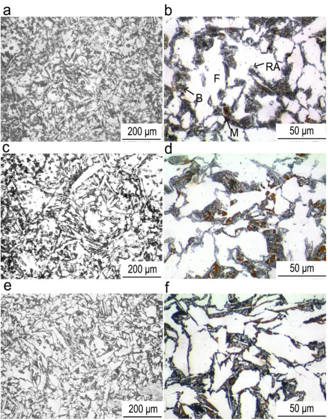
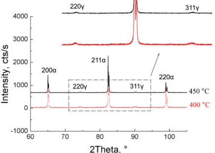
The isothermal bainite transformation (IBT) was studied by holding at 400, 450 and 500◦C for 900 s (15 min). The representative and homogenous microstructures are shown in Figure9(OM) and Figure10(SEM), indicating the successful production of typical TRIP steel microstructures [26]. Figure9b,d,f show the ferrite in grey/white, bainite in dark grey/bluish, martensite in brown and RA in grey/white. After holding at 400◦C, the microstructure consisted of ferrite, bainite, RA and martensite (Figure9a,b). As seen in Figure10a, bainite included bainitic ferrite, where film-shaped retained austenite/martensite constituent (RA/M) was clamped by ferritic laths and granular bainite, where globular RA/M was surrounded by irregular-shaped ferrite. After holding at a higher temperature of 450◦C the martensite fraction increased (Figures9d and10b). The increasing of holding temperature up to 500◦C slightly decreased the martensite fraction (Figure9f) and promoted some pearlite formation (Figure10c,d). It is well known that pearlite is harmful to the TRIP steels; pearlite consumes carbon and reduces the carbon content in austenite. A decreased carbon content in austenite decreases the austenite stability and the fraction of RA in the room temperature microstructure [29,30]. Due to the presence of pearlite after holding at 500◦C this heat treatment condition was regarded as inappropriate for the TRIP steel production and thus the RA fraction was measured only for the samples held at 400 and 450◦C (Figure11). Based on the direct comparison method, the RA fraction was measured to be 5.2% and 4.2% after holding at 400 and 450◦C, respectively.
Metals2019,9, 449 9 of 14 Metals 2019, 8, x FOR PEER REVIEW 10 of 14 during quenching from 450 °C (c.f. Figure 9b,d) and a lower RA fraction was obtained. Similar results
were reported in Ref. [34].
Figure 9. Optical microstructures after holding at (a,b) 400 °C, (c,d) 450 °C and (e,f) 500 °C for 900 s
(15 min) following holding at 750 °C for 240 s: (a,c,e) nital and (b,d,f) colour etched microstructures.
Ferrite is shown with grey/white, bainite with dark grey/bluish, retained austenite with grey/white
and martensite with brown colours in (b,d,f). F is ferrite, B is bainite, M is martensite and RA is
retained austenite.
Figure 9.Optical microstructures after holding at (a,b) 400◦C, (
c,d) 450◦C and (
e,f) 500◦C for 900 s
(15 min) following holding at 750◦C for 240 s: (a,c,e) nital and (b,d,f) colour etched microstructures. Ferrite is shown with grey/white, bainite with dark grey/bluish, retained austenite with grey/white and martensite with brown colours in (b,d,f). Fis ferrite,Bis bainite,Mis martensite andRAis retained austenite.
Metals2019,9, 449 10 of 14 Metals 2019, 8, x FOR PEER REVIEW 11 of 14
Figure 10. Microstructures after holding at (a) 400 °C, (b) 450 °C and (c,d) 500 °C for 900 s (15 min)
following holding at 750 °C for 240 s. F is ferrite, BF is bainitic ferrite, GB is granular bainite, RA/M is
retained austenite/martensite constituent, M is martensite and P is pearlite.
Figure 11. X‐ray diffractograms after holding at 400 and 450 °C for 900 s (15 min).
3.4. Tensile Properties
Ferrite‐martensite DP steels and multi‐phase TRIP steels have been successfully produced in the
laboratory using the modified strip casting technology proposed in the above sections. Figure 12
shows the engineering stress‐engineering strain curves for a DP steel that has a ferrite fraction of 0.69
± 0.02 (designated as DP) and TRIP steels held at 400 and 450 °C (designated as TC 400 and TC 450,
respectively). The curves indicate a typical continuous yielding behaviour observed in the multi‐ Figure 10.Microstructures after holding at (a) 400◦C, (b) 450◦C and (c,d) 500◦C for 900 s (15 min) following holding at 750◦C for 240 s.Fis ferrite,BFis bainitic ferrite,GBis granular bainite,RA/Mis retained austenite/martensite constituent,Mis martensite andPis pearlite.
Metals 2019, 8, x FOR PEER REVIEW 11 of 14
Figure 10. Microstructures after holding at (a) 400 °C, (b) 450 °C and (c,d) 500 °C for 900 s (15 min)
following holding at 750 °C for 240 s. F is ferrite, BF is bainitic ferrite, GB is granular bainite, RA/M is
retained austenite/martensite constituent, M is martensite and P is pearlite.
Figure 11. X‐ray diffractograms after holding at 400 and 450 °C for 900 s (15 min).
3.4. Tensile Properties
Ferrite
‐
martensite
DP
steels
and
multi
‐
phase
TRIP
steels
have
been
successfully
produced
in
the
laboratory
using
the
modified
strip
casting
technology
proposed
in
the
above
sections.
Figure
12
shows
the
engineering
stress
‐
engineering
strain
curves
for
a
DP
steel
that
has
a
ferrite
fraction
of
0.69
±
0.02
(designated
as
DP)
and
TRIP
steels
held
at
400
and
450
°C
(designated
as
TC
400
and
TC
450,
respectively).
The
curves
indicate
a
typical
continuous
yielding
behaviour
observed
in
the
multi
‐
Metals2019,9, 449 11 of 14
The critical driving force (Gcritical) for bainite transformation can be expressed by the following
equation [31]:
Gcritical =AT−B (1)
whereAandBare positive constants related to the steel chemical compositions [32,33] andTis the temperature. When the temperature decreased from ferrite-austenite two-phase region to bainite transformation region, the bainite formed during the holding and the carbon diffused from bainitic laths to austenite. Increasing the IBT temperature from 400 to 450◦C led to an increase inGcritical. This
indicates that the transformation from austenite to bainite becomes more difficult with an increase in temperature, leading to a lower fraction of bainite. For a lower fraction of bainite formation, the content of carbon partitioning from bainitic ferrite laths into austenite was lower and thus the austenite became less enriched in carbon. Therefore, a less stable austenite transformed to martensite during quenching from 450◦C (c.f. Figure9b,d) and a lower RA fraction was obtained. Similar results were reported in Ref. [34].
3.4. Tensile Properties
Ferrite-martensite DP steels and multi-phase TRIP steels have been successfully produced in the laboratory using the modified strip casting technology proposed in the above sections. Figure12 shows the engineering stress-engineering strain curves for a DP steel that has a ferrite fraction of 0.69 ±0.02 (designated as DP) and TRIP steels held at 400 and 450◦C (designated as TC 400 and TC 450, respectively). The curves indicate a typical continuous yielding behaviour observed in the multi-phase steels [35]. The DP steel showed a higher yield strength (YS) of 350 MPa, a higher UTS of 589 MPa and a lower TE of 22.4% than the TRIP steels. The TRIP steel held at 400◦C exhibited a lower UTS of 541 MPa and a larger TE of 33%, while the TRIP steel held at 450◦C had a higher UTS of 568 MPa and a lower TE of 31%. These two TRIP steels have similar YS of 332 (TC 400) and 328 (TC 450) MPa, respectively. The slightly larger TE in the sample held at 400◦C was probably ascribed to a higher fraction of RA for this processing condition (5.2% vs. 4.2%), leading to a stronger TRIP effect [8,36].
Metals 2019, 8, x FOR PEER REVIEW 12 of 14 phase steels [35]. The DP steel showed a higher yield strength (YS) of 350 MPa, a higher UTS of 589
MPa and a lower TE of 22.4% than the TRIP steels. The TRIP steel held at 400 °C exhibited a lower
UTS of 541 MPa and a larger TE of 33%, while the TRIP steel held at 450 °C had a higher UTS of 568
MPa and a lower TE of 31%. These two TRIP steels have similar YS of 332 (TC 400) and 328 (TC 450)
MPa, respectively. The slightly larger TE in the sample held at 400 °C was probably ascribed to a
higher fraction of RA for this processing condition (5.2% vs. 4.2%), leading to a stronger TRIP effect
[8,36].
Figure 12. (a) Engineering stress‐engineering strain curves and (b) comparison of mechanical
properties for the studied steels and DP and TRIP steels conventionally cold/hot rolled in the steel
industry [37].
The tensile properties obtained in the present study are comparable to the properties obtained
in industrially cold rolled DP and TRIP steels (Figure 12b). The studied DP steel showed a little lower
UTS than DP 590, however, together with a little larger TE. Obviously, for the studied TRIP steels,
the TE is large enough, whereas the UTS is much lower in comparison with TRIP 690. Although a
lower strength is obtained in the present study, the results indicate a feasibility to produce DP and
TRIP steels using the modified strip casting. Recent studies have shown that the improvement of
tensile properties can also be achieved through the deformation in the austenite temperature region
followed by accelerated cooling and warm deformation in the ferrite temperature region, leading to
finer microstructures [38]. In addition, the microalloying with niobium, vanadium and molybdenum
can also improve the tensile strength via precipitation and solid solution strengthening [39,40]. Thus,
further research on the enhancement of tensile properties in DP and TRIP steels produced by the
modified strip casting can be dedicated to the investigation of effects of thermo‐mechanical control
process and alloying. 4. Conclusions
The modified strip casting with the addition of a continuous annealing stage was shown to be a
promising technology for producing ferrite‐martensite DP and multi‐phase TRIP steels. The initial
ferrite‐pearlite microstructure was obtained via the adjustment of holding temperature during the
first step of heat treatments of the modified strip casting. Following this, to produce DP steels, various
temperatures and times of holding during intercritical annealing can result in different fractions of
ferrite and martensite; to produce TRIP steels, at first ~50% ferrite should be obtained during
intercritical annealing and bainite and retained austenite, together with a small amount of martensite,
can be formed as a result of isothermal bainite transformation followed by cooling to room
temperature.
The tensile strength was lower but the ductility was higher, in the studied steels than those in
the conventionally produced DP and TRIP steels. Further enhancement of mechanical properties in
strip cast steels can be achieved via the introduction of thermo‐mechanical control process and
microalloying, leading to the strengthening from grain refinement and precipitation. These require Figure 12.(a) Engineering stress-engineering strain curves and (b) comparison of mechanical properties for the studied steels and DP and TRIP steels conventionally cold/hot rolled in the steel industry [37].
The tensile properties obtained in the present study are comparable to the properties obtained in industrially cold rolled DP and TRIP steels (Figure12b). The studied DP steel showed a little lower UTS than DP 590, however, together with a little larger TE. Obviously, for the studied TRIP steels, the TE is large enough, whereas the UTS is much lower in comparison with TRIP 690. Although a lower strength is obtained in the present study, the results indicate a feasibility to produce DP and TRIP steels using the modified strip casting. Recent studies have shown that the improvement of tensile properties can also be achieved through the deformation in the austenite temperature region followed by accelerated cooling and warm deformation in the ferrite temperature region, leading to
Metals2019,9, 449 12 of 14
finer microstructures [38]. In addition, the microalloying with niobium, vanadium and molybdenum can also improve the tensile strength via precipitation and solid solution strengthening [39,40]. Thus, further research on the enhancement of tensile properties in DP and TRIP steels produced by the modified strip casting can be dedicated to the investigation of effects of thermo-mechanical control process and alloying.
4. Conclusions
The modified strip casting with the addition of a continuous annealing stage was shown to be a promising technology for producing ferrite-martensite DP and multi-phase TRIP steels. The initial ferrite-pearlite microstructure was obtained via the adjustment of holding temperature during the first step of heat treatments of the modified strip casting. Following this, to produce DP steels, various temperatures and times of holding during inter critical annealing can result in different fractions of ferrite and martensite; to produce TRIP steels, at first ~50% ferrite should be obtained during inter critical annealing and bainite and retained austenite, together with a small amount of martensite, can be formed as a result of isothermal bainite transformation followed by cooling to room temperature.
The tensile strength was lower but the ductility was higher, in the studied steels than those in the conventionally produced DP and TRIP steels. Further enhancement of mechanical properties in strip cast steels can be achieved via the introduction of thermo-mechanical control process and microalloying, leading to the strengthening from grain refinement and precipitation. These require further investigation. The results presented in this work indicate a strong feasibility to produce homogenous microstructures of DP and TRIP steels in industry using the novel technology of the modified strip casting.
Author Contributions:E.V.P. and A.G.K. conceived the idea. Z.X. carried out the experiments. Y.Z. wrote the draft. All the authors reviewed this paper.
Funding: The JEOL JSM-7001F FEG-SEM at the Electron Microscopy Centre of University of Wollongong (Australia) was funded by the Australian Research Council grant LE0882613.
Conflicts of Interest:The authors declare no conflict of interest.
References
1. Killmore, C.R.; Edelman, D.G.; Carpenter, K.R.; Kaul, H.R.; Williams, J.G.; Campbell, P.C.; Blejde, W.N. Recent product developments with ultra-thin cast strip products produced by the CASTRIP®process.Mater. Sci. Forum 2010,654–656, 198–201. [CrossRef]
2. Ge, S.; Isac, M.; Guthrie, R.I.L. Progress of strip casting technology for steel; historical developments.ISIJ Int. 2012,52, 2109–2122. [CrossRef]
3. Zapuskalov, N. Comparison of continuous strip casting with conventional technology. ISIJ Int. 2003,43, 1115–1127. [CrossRef]
4. Carpenter, K.R.; Killmore, C.R. The effect of Nb on the continuous cooling transformation curves of ultra-thin strip CASTRIP©steels.Metals2015,5, 1857–1877. [CrossRef]
5. Xiong, Z.P.; Kostryzhev, A.G.; Stanford, N.E.; Pereloma, E.V. Microstructures and mechanical properties of dual phase steel produced by laboratory simulated strip casting.Mater. Des.2015,88, 537–549. [CrossRef] 6. Xiong, Z.P.; Kostryzhev, A.G.; Stanford, N.E.; Pereloma, E.V. Effect of deformation on microstructure and
mechanical properties of dual phase steel produced via strip casting simulation.Mater. Sci. Eng.2016,651, 291–305. [CrossRef]
7. Xiong, Z.P.; Saleh, A.A.; Kostryzhev, A.G.; Pereloma, E.V. Strain induced ferrite formation and its effect on mechanical properties in strip cast dual phase steels.J. Alloys Compd.2017,721, 291–306. [CrossRef] 8. Xiong, Z.P.; Kostryzhev, A.G.; Saleh, A.A.; Chen, L.; Pereloma, E.V. Microstructures and mechanical properties
of TRIP steel produced by strip casting simulated in the laboratory. Mater. Sci. Eng. 2016,664, 26–42. [CrossRef]
9. Xiong, Z.P.; Kostryzhev, A.G.; Chen, L.; Pereloma, E.V. Microstructure and mechanical properties of strip cast TRIP steel subjected to thermo-mechanical simulation.Mater. Sci. Eng. A2016,677, 356–366. [CrossRef]
Metals2019,9, 449 13 of 14
10. Daamen, M.; Haase, C.; Dierdorf, J.; Molodov, D.A.; Hirt, G. Twin-roll strip casting: A competitive alternative for the production of high-manganese steels with advanced mechanical properties.Mater. Sci. Eng. A2015,
627, 72–81. [CrossRef]
11. Ge, S.; Isac, M.; Guthrie, R.I.L. Progress in strip casting technologies for steel; technical developments.ISIJ Int. 2013,53, 729–742. [CrossRef]
12. Xu, Y.S.; Dan, W.J.; Ren, C.; Huang, T.T.; Zhang, W.G. Study of the mechanical behavior of dual-phase steel based on crystal plasticity modelling considering strain partitioning.Metals2018,8, 782. [CrossRef] 13. Mazaheri, Y.; Kermanpur, A.; Najafizadeh, A. Strengthening mechanisms of ultrafine grained dual phase
steels developed by new thermomechanical processing.ISIJ Int.2015,55, 218–226. [CrossRef]
14. Balbi, M.; Alvarez-Armas, I.; Armas, A. Effect of holding time at an inter critical temperature on the microstructure and tensile properties of a ferrite-martensite dual phase steel.Mater. Sci. Eng.2018,733, 1–8. [CrossRef]
15. ZareiHanzaki, A.; Yue, S. Ferrite formation characteristics in Si-Mn TRIP steels.ISIJ Int.1997,37, 583–589. [CrossRef]
16. Zaefferer, S.; Ohlert, J.; Bleck, W. A study of microstructure, transformation mechanisms and correlation between microstructure and mechanical properties of a low alloyed TRIP steel. Acta Mater. 2004, 52, 2765–2778. [CrossRef]
17. Pereloma, E.V.; Gazder, A.A.; Timokhina, I.B. Retained austenite: Transformation-induced plasticity. InEncyclopedia of Iron, Steel and Their Alloys; Colas, R., Totten, G.E., Eds.; CRC Press: New York, NY, USA, 2016; pp. 3088–3103.
18. Tomota, Y.; Tokuda, H.; Adachi, Y.; Wakita, M.; Minakawa, N.; Moriai, A.; Morii, Y. Tensile behavior of TRIP-aided multi-phase steels studied by in situ neutron diffraction. Acta Mater. 2004, 52, 5737–5745. [CrossRef]
19. Xiong, Z.P.; Saleh, A.A.; Marceau, R.K.W.; Taylor, A.S.; Stanford, N.E.; Kostryzhev, A.G.; Pereloma, E.V. Site-specific atomic-scale characterisation of retained austenite in a strip cast TRIP steel.Acta Mater.2017,
134, 1–15. [CrossRef]
20. Jacques, P.J.; Ladriere, J.; Delannay, F. On the influence of interactions between phases on the mechanical stability of retained austenite in transformation-induced plasticity multiphase steels.Metall. Mater. Trans. 2001,32, 2759–2768. [CrossRef]
21. Xiong, Z.P.; Jacques, P.J.; Perlade, A.; Pardoen, T. Ductile and intergranular brittle fracture in a two-step quenching and partitioning steel.Scr. Mater.2018,157, 6–9. [CrossRef]
22. Sugimoto, K.; Usui, N.; Kobayashi, M.; Hashimoto, S. Effects of volume fraction and stability of retained austenite on ductility of TRIP-aided dual-phase steels.ISIJ Int.1992,32, 1311–1318. [CrossRef]
23. Pichler, A.; Traint, S.; Hebesberger, T.; Stiaszny, P.; Werner, E.A. Processing of thin sheet multiphase steel grades.Steel Res. Int.2007,78, 216–223. [CrossRef]
24. Santos, D.B.; Bruzszek, R.K.; Rodrigues, P.C.M.; Pereloma, E.V. Formation of ultra-fine ferrite microstructure in warm rolled and annealed C–Mn steel.Mater. Sci. Eng.2003,346, 189–195. [CrossRef]
25. Kim, S.J.; Lee, C.; Choi, I.; Lee, S. Effects of heat treatment and alloying elements on the microstructures and mechanical properties of 0.15 wt pct C transformation-induced plasticity-aided cold-rolled steel sheets.
Metall. Mater. Trans.2001,32, 505–514. [CrossRef]
26. Zhao, J.W.; Jiang, Z.Y. Thermomechanical processing of advanced high strength steels.Prog. Mater. Sci.2018,
94, 174–242. [CrossRef]
27. Liu, L.; He, B.B.; Huang, M.X. The role of transformation-induced plasticity on the development of advanced high strength steels.Adv. Eng. Mater.2018,20, 1701083. [CrossRef]
28. Strezov, L.; Herbertson, J. Experimental studies of interfacial heat transfer and initial solidification pertinent to strip casting.ISIJ Int.1998,38, 959–966. [CrossRef]
29. Seol, J.B.; Raabe, D.; Choi, P.P.; Im, Y.R.; Park, C.G. Atomic scale effects of alloying, partitioning, solute drag and austempering on the mechanical properties of high-carbon bainitic–austenitic TRIP steels.Acta Mater. 2012,60, 6183–6199. [CrossRef]
30. Hosseini, S.M.K.; Zaeri-Hanzaki, A.; Yue, S. Effect of austenite deformation in non-recrystallization region on microstructure development in low-silicon content TRIP-assisted steels.Mater. Sci. Eng.2014,618, 63–70. [CrossRef]
Metals2019,9, 449 14 of 14
31. Li, S.; Zhu, R.; Karaman, I.; Arroyave, R. Development of a kinetic model for bainitic isothermal transformation in transformation-induced plasticity steels.Acta Mater.2013,61, 2884–2894. [CrossRef]
32. Fazeli, F.; Militzer, M. Modelling simultaneous formation of bainitic ferrite and carbide in TRIP steels.ISIJ Int. 2014,52, 650–658. [CrossRef]
33. Gaude-Fugarolas, D.; Jacques, P.J. A new physical model for the kinetics of the bainite transformation.ISIJ Int. 2006,46, 712–717. [CrossRef]
34. Ranjan, R.; Beladi, H.; Singh, S.B.; Hodgson, P.D. Thermo-mechanical processing of TRIP-aided steels.
Metall. Mater. Trans.2015,46, 3232–3247. [CrossRef]
35. Bhadeshia, H.K.D.H. Anomalies in carbon concentration determinations from nanostructured bainite.
Mater. Sci. Technol.2015,31, 758–763. [CrossRef]
36. Seo, E.J.; Cho, L.; Estrin, Y.; de Cooman, B.C. Microstructure-mechanical properties relationships for quenching and partitioning (Q&P) processed steel.Acta Mater.2016,113, 124–139.
37. Nippon Steel & Sumitomo Metal Corporation. Available online:http://www.nssmc.com/en/(accessed on 10 January 2019).
38. Kostryzhev, A.; Marenych, O. New technology to produce 1 GPa low carbon microalloyed steels from cast strip.Metals2018,8, 662. [CrossRef]
39. Kostryzhev, A.; Singh, N.; Chen, L.; Killmore, C.; Pereloma, E.V. Comparative effect of Mo and Cr on microstructure and mechanical properties in NbV-microalloyed bainitic steels.Metals2018,8, 134. [CrossRef] 40. Grajcar, A.; Kwa´sny, W.; Zalecki, W. Microstructure-property relationships in TRIP aided medium-C bainitic
steel with lamellar retained austenite.Mater. Sci. Technol.2015,31, 781–794. [CrossRef]
©2019 by the authors. Licensee MDPI, Basel, Switzerland. This article is an open access article distributed under the terms and conditions of the Creative Commons Attribution (CC BY) license (http://creativecommons.org/licenses/by/4.0/).