In Proceedings of 2nd IEEE International Symposium on Object-Oriented Real-Time Distributed Computing (ISORC’99), 2-5 May 1999, Saint-Malo, France
Applying Use Cases for the Requirements Validation
of Component-Based Real-Time Software
Wolfgang Fleisch
Institute for Industrial Automation and Software Engineering
University of Stuttgart
[email protected]
Abstract
Component-based software development is a promising way to improve quality, time to market and handle the increasing complexity of software for real-time systems. In this paper the basic properties of an event-triggered com-ponent model for real-time software are introduced. For the early exposure of design errors a process for the simulation based validation of component-based software applying use cases is presented. A template for structuring use cases helps gathering the course-oriented require-ments which describe the required behaviour of the com-posed software. Requirements sequence diagrams are extracted from the use cases and compared with the simulated behaviour of the component-based software. A case study of a power window control from the automotive body electronics domain demonstrates practical experience with applying use cases for the requirements validation.
1.
Introduction
In the IAS (Institute for Industrial Automation and Soft-ware Engineering) research project ‘Component-Based Software Development and Evaluation’ concepts, tech-niques and tools are developed to manage the increasing software complexity of distributed real-time systems, to improve software quality and to reduce time to market. In our point of view component-based software development means that new application software will be composed from a set of predefined, scalable and configurable soft-ware components, which have been explicitly developed for multiple usage. In the following, the word component always denotes a software component. The components have to meet the special requirements of embedded target processors, for example runtime efficiency and minimum demands for memory. In addition, the requirements for local and distributed communication between software
components have to be met. The idea of applying a com-ponent model and a comcom-ponent-based software archi-tecture promises many advantages as for example easier and faster construction, adaptation, modification and distribution of software applications for complex real-time systems.
Assumed that we are using a component-based system architecture, the following aspects should be remarked: the software components which have been explicitly developed for multiple usage are supposed to have a vali-dated or even a verified behaviour at their interfaces, which gives them a better quality. But when composing a new application software with such components it can not be concluded for the composed system that it has the same level of correctness compared to the single components. For that reason, especially the interactions between the software components have to be reviewed for the vali-dation of the system behaviour.
2.
Component-Based Software Development
2.1 Component Properties
A software component (Figure 1) shows black-box behaviour at its interface. The internal state and the attributes of the component are strongly encapsulated. The encapsulated internal part of a component is exclusively communicating with its interface. The interface of a com-ponent provides inputs and outputs which can be connected with other components.
Component Body
Input (0-n) Output (0-n)
Comp. Interface
2.2 Modelling Component-Based Application
Software
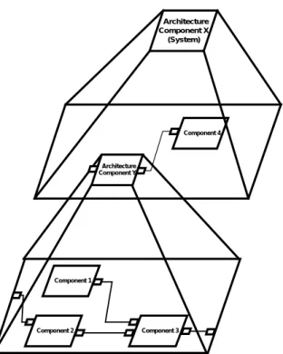
The modelling of a component-based real-time software application works fundamentally in two steps. In a first step, a planned application is refined hierarchically top down with architecture components (Figure 2). At the beginning, the architecture components are empty com-ponents and just outline the structure of an application to be designed. In the second step the developer fills up the empty architecture components with components from a component library to define the individual behaviour of an application. This means that the developer works of prime importance on the architecture level instead of coding on low level the complete software line by line. Considering the efficiency requirements of embedded real-time systems the component-based model structure is intended as a high level description for code generation and validation activi-ties. Architecture Component X (System) Architecture Component Y Component 4 Component 2 Component 1 Component 3
Figure 2: Hierarchical component-based application structure
For modelling component-based applications and library components, ‘Architecture Description Languages’ (ADL) offer some essential properties for composition and con-figuration of component-based software although they have originally not been developed for. The ADL-based tools RAPIDE [1], [2] from Stanford University and ObjecTime Developer/ROOM [3], [4] from ObjecTime are currently used at the IAS for modelling and simulation. A textual or graphical ADLcovers the structure model
description as well as the component behaviour and inter-face description. Further information about current architecture description languages can be found in Bass et. al. [5].
2.3 Component-Based Software versus
Object-Oriented Software
The reasons for applying a component model for real-time software are the advantages of the underlying interface connection architecture. In an object-oriented software architecture the connections (message sending commands) are buried in the objects as illustrated in (Figure 3). This has a number of disadvantages. For example that the en-capsulated objects and the architecture are not clearly separate entities. Although the interface methods of objects can be defined before the implementation, the connections are only defined when the objects are built. So, the archi-tecture has likely evolved as the system was built and was not predefined as a plan or outline of the system. Simple changes by replacing only one object for example may cause changes of the architecture. Supposed object 2 shall be exchanged, all method calls from other objects to the provided methods of object 2 have to be changed inside the encapsulated code of these objects. This is not a sufficient support for comfortable changes or extensions.
Object 1 Interface 1
Object 2 Interface 2 Methods
Figure 3: Example for an object-oriented architecture
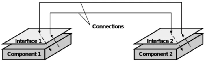
In a component-based interface connection architecture the software structure is independent from the encapsulated internal behaviour of the components (Figure 4). The decoupling of the encapsulated internal component body from the architecture is achieved using an interface similar to hardware circuits with a defined set of inputs and out-puts. The encapsulated component body is exclusively communicating with its interface. This strict separation of architecture and components enables flexible usage of standard components (“components off the shelf”) [5] plugged together via their interfaces. It supports easy modification and adaptation of the component-based soft-ware. Another advantage of an interface connection archi-tecture is that when applying validated components, current validation activities only have to concentrate on analysing the architecture description.
Component 1 Interface 1
Component 2 Interface 2 Connections
Figure 4: Example for a component-based interface connection architecture
Component-based software is a specialisation of object-oriented software. The component model which is currently developed at the IAS is based on object-oriented basic concepts like hierarchy, encapsulation and com-position. The inner part of the components may even be modelled object-oriented as long as they show the required black-box behaviour at their interfaces.
2.4 Component Model for Real-Time Software
2.4.1 OverviewAn event-triggered component model for distributed real-time software is currently specified at the IAS. Beside of that a time-triggered component model for distributed real-time software is under construction [6]. In the following, a brief overview about the basic properties of the event-triggered component model is given. The component model defines the following different sub-models:
• structure model
• communication model
• execution model
2.4.2 Structure Model
The structure model of a component-based application software consists of architecture components and com-ponents as presented in Figure 2. Architecture comcom-ponents and components are wired with connections. The elements of the structure model can be described by using an archi-tecture description language. To support hierarchy, a set of connected components can be compound to an architecture component, which behaves the same at its interface as a basic component does.
2.4.3 Communication Model
Communication between components is intended to be asynchronous and message based. Depending on the content of messages, either event messages or state messages are used. When using event-messages, queues are necessary for all inputs. Messages do not contain infor-mation about their sender and receiver. This inforinfor-mation is included in the connections of the structure model.
2.4.4 Execution Model
The activation of components at run-time is event-triggered and can be defined nearly independent from the structure of an application. A Component is activated by receiving an input message at its interface. The runtime execution can be managed in different ways like
1. task or thread management of a real-time operating system
2. simple control loop activating the components in a predefined order (for example FIFO event queue) 3. activation by connected timer components.
3.
Requirements Engineering
3.1 Motivation
Distributed real-time systems are usually concurrent, have to be reliable and have to meet timing constraints. A strongly increasing application area for real-time systems are embedded systems, which received their name because they are embedded in a technical process. The application example of an automotive power window control presented in chapter 5 also belongs to the domain of embedded systems. A measure for the current complexity of automotive control systems is that in a today’s car there are working up to 75 microcontrollers, interconnected via communication busses as for example CAN (Controller Area Network) [7]. The number of control units has strongly increased over the last years and it is expected that especially software will have an enormous rise in com-plexity over the next decade [8], [9]. The software has to match customer wishes and requirements in any cases. This means that increasing software complexity results in an increasing number of requirements. Software quality and correctness of a new automotive system can not be validated as it is done with standard PC software. A driver will not accept to test his new car in daily traffic. Violating or forgetting just one requirement may cause serious consequences. For example ignoring the stop message from an anti-pinch protection sensor in just one case of the control software of a power window is a question of vital importance.
3.2 Definitions
Requirements engineering is a sub-discipline of system engineering. Its goal is to help customer and contractor to describe their wishes to produce a new system and to support the developer to understand and structure these wishes and to ensure that the product meets the imposed requirements. The biggest part of the requirements is specified during the analysis phase and has to be validated
and traced through the following development phases design, implementation and system integration. In the requirements engineering process the essential functional and non-functional requirements for a system to be produced, are discussed, specified, analysed, validated and documented.
Boehm [10] distinguishes between two techniques for reviewing requirements specifications, verification and validation. He explains the difference between both activi-ties as follows:
Verification: „Am I building the product right ?“ Validation: „Am I building the right product ?“
The IEEE-Standard 830-1984 [11] defines validation as follows: “Validation: The process of evaluating software at the end of the software development process to ensure compliance with software requirements“. This is achieved by inspecting the following criteria
• completeness
• consistency
• feasibility
• and testability
within an actual requirements specification and tracing the requirements through the whole development process. Validation can be made with different manual and com-puter aided techniques. In [10] good overviews about verification and validation techniques are presented.
3.3 Requirements Engineering for
Component-Based Software
When composing a component-based application software with predefined components from a component library, it is a logical conclusion that the overall number of errors will be less due to reusing validated components with a better quality. But when composing and configuring com-ponents for a new application, design errors will still occur for example by disregarding or forgetting some requirements. In addition to other validation techniques like reviews and consistency checks (static structure and data types), we have chosen simulation to detect design errors in the dynamic behaviour in the early design phase. Simulation has been chosen because in many cases of software development for an embedded real-time system, the distributed target system is not available for rapid prototyping at the beginning. Therefore it is helpful to simulate the designed software structure and its dynamic behaviour by using a simulation model as for example in [12].
Another reason for selecting simulation for the require-ments validation is the increasing importance of automatic target code generation from modelling and simulation
tools. It is assumed that a planned tool for component-based software development will also provide target code generation in the future. When using generated code from a component-based model the currently used validation technique ‘conformance testing’ will not work anymore. Conformance testing means that the dynamic behaviour of the simulation model is recorded and compared to the dynamic behaviour of the executed code during black-box testing on the target system. But when the simulation model and the executable code are both extracted from the same component-based model, they are based on the same set of data.
However, most nowadays simulation tools lack support for efficient structured requirements specification and valida-tion mechanisms. Deviavalida-tions of the simulated behaviour from single requirements have to be checked intuitively by the developer by hand. For that reason, a new requirements validation process applying use cases and simulation is presented in the next chapter.
4.
Applying Use Cases for the Validation of
Component-Based Software
4.1 Describing Requirements with Structured
Use Cases
Use cases as defined by Jacobsen [13] are not concretely defined, and leave a lot to interpretation by the user. According to Jacobson, “A use case is a specific way of using the system by performing some part of the func-tionality. Each use case constitutes a complete course of events initiated by an actor and the system....The collected use cases specify all the existing ways of using the system”[13]. This description of use cases has been popu-larised in nearly all object-oriented methodologies to date. Use cases lead to a scenario-driven analysis model. The actors used in this analysis model are not generally corre-sponding with the components in the later component-based design model. It depends on the behaviour of each actor if a corresponding component can be found in the component library or if more than one library component have to be selected and connected to design the required behaviour of an actor in the later component-based design process.
Use cases describe courses of events between an actor and the system. One course of events is called scenario. An actor plays a role concerning to a selected function. An actor can be a human being, a machine or a computer system. At this time it has to be noticed that use cases for themselves are not object-oriented but course-oriented. They describe dynamic behaviour in a system-oriented view. Because of their course-oriented and system-oriented view, they are a very good fit for the requirements
specifi-cation for component-based software, where the required interactions between the composed components have to be analysed and validated.
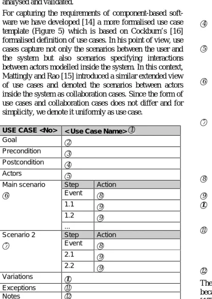
For capturing the requirements of component-based soft-ware we have developed [14] a more formalised use case template (Figure 5) which is based on Cockburn’s [16] formalised definition of use cases. In his point of view, use cases capture not only the scenarios between the user and the system but also scenarios specifying interactions between actors modelled inside the system. In this context, Mattingly and Rao [15] introduced a similar extended view of use cases and denoted the scenarios between actors inside the system as collaboration cases. Since the form of use cases and collaboration cases does not differ and for simplicity, we denote it uniformly as use case.
USE CASE <No> < Use Case Name> 1
Goal 2
Precondition 3
Postcondition 4
Actors 5
Main scenario Step Action
6 Event 8
1.1 9
1.2 9
...
Scenario 2 Step Action
7 Event 8 2.1 9 2.2 9 Variations 10 Exceptions 11 Notes 12
Figure 5: Use case template
Each use case describes how the goal of a selected actor is accomplished or fails. The simple use case template in Figure 5 provides a structured form for writing use cases which are not only helpful for gathering design require-ments but also support later validation of a component-based software. Keeping the use cases form simple has been the ultimate challenge and will keep user acceptance high. The structured use case is defined as follows:
1 Use case name: Provides a short meaningful
name.
2 Represents the goal of the use case.
3 Preconditions indicate circumstances that must
be true prior to the invocation of any scenario of the use case. Alternatives of preconditions are possible. They are ordered by numbering with letters (a,b,c...).
4 The postcondition validate that the main scenario and all alternative scenarios successfully achieved the stated goal of the use case.
5 An actor plays a role (e.g. user, machine,
com-puter system or software component), which influences the system or is influenced by the system during a scenario.
6 Each use case has only one main scenario. The
main scenario is a sequence of steps that the role or actor is likely to take in order to accomplish the goal of the use case. The main scenario is intuitively the easiest way to reach the goal. 7 Alternative scenarios are optional. Each use case
has zero to many alternative scenarios. The alter-native scenario is a different sequence of steps that the role of actor can take that also accom-plishes the goal of the use case. Usually they are triggered by another event or have different pre-conditions.
8 The event which triggers the sequence of steps in the scenario.
9 Single step in a scenario.
10 Variations are scenarios which differ just insignifi-cantly in one step from another scenario or just the role or actor is varied.
11 The exception scenario is a sequence of steps
the role or actor takes when the task is inter-rupted. The postcondition that validates the goal of the use case is not necessarily true after the exception scenario has been taken.
12 Notes for comments.
The template has been realised as a MS-Word97-Table because nowadays UML (Unified Modelling Language) [17] modelling tools do not enable structuring use cases in a user-friendly manner.
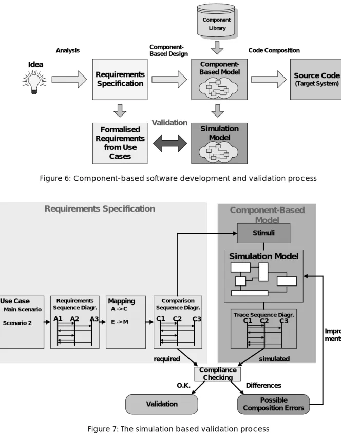
4.2 The Validation Process
The component-based software development and valida-tion process is shown in Figure 6. The development process starts with gathering requirements. The course-oriented part of the requirements is described in structured use cases presented in the previous chapter. After that the developer is building up the component-based model derived from the requirements and by selecting suitable components from the component library. The component-based model contains all structure and behaviour descrip-tions which are necessary for the simulation model and the code composition for the target system.
Requirements Specification Analysis
Component-Based Model Source Code
(Target System) Idea
Component Library
Component-Based Design Code Composition
Formalised Requirements from Use Cases Simulation Model Validation
Figure 6: Component-based software development and validation process
Compliance Checking Possible Composition Errors Validation Differences O.K.
Requirements Specification
required Use Case Main Scenario Scenario 2 Requirements Sequence Diagr. A1 A2 A3 Mapping A -> C E -> M Comparison Sequence Diagr. C1 C2 C3Component-Based
Model
Simulation Model
StimuliTrace Sequence Diagr.
Improve-ments
simulated
C1 C2 C3
Figure 7: The simulation based validation process
The validation (Figure 7) itself is based on compliance checking between the formalised required behaviour derived from the use cases and the simulated behaviour of the simulation model. The simulation model, which is described with an ADL, is a subset of the
component-based model and contains all information about the sub-model views structure, communication and execution of the modelled application.
The formalisation of the required behaviour starts with the structured use cases. Each scenario of the collected use
cases has to be transformed by the developer into a re-quirements sequence diagram, describing the ordered interactions between the analysed actors (Ax). The sequence diagrams are according to the UML standard [17].
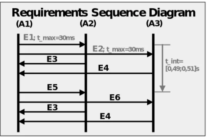
Requirements Sequence Diagram
E1; t_max=30ms E3 E4 E5 E6 E3 E4 t_int= [0,49;0,51]s E2; t_max=30ms
(A1) (A2) (A3)
Figure 8: Requirements sequence diagram
In addition to the causal ordering of event communication between the actors also real-time constraints can be specified in a sequence diagram. Timing requirements can be defined with a minimum time, a maximum time or with a time interval. Figure 8 contains the two different kinds of timing requirements:
• timed event
• delay
A timed event means that the actions connected to the event consume time. In Figure 8 the t_max specifies the maximum time for sending the event E1 from actor A1 until it influences the receiving actor A2 by receiving event E1. This is necessary because the actor-oriented view in the use case driven analysis model is different to the com-ponent view in the comcom-ponent-based simulation model. In the component-based simulation model, which is a subset of the component-based model, not every component is corresponding exactly to one actor. It is possible that a sent event is passed through many components in the modelled component structure until it affects the component corresponding to the receiving actor.
A delay is a timing requirement between the occurrence of two events which can also be seen in Figure 8. The time interval indicates that event E5 has to occur after the occurrence of event E1 with a delay time in the specified interval range.
In a further step, the requirements sequence diagrams have to be mapped to the name space of the component-based simulation model to supply an automated compliance check between requirements sequences and the recorded event trace sequences from the simulation. After that the
required behaviour is described in a set of comparison sequence diagrams which use corresponding component identifiers. Actors are mapped to components and events are mapped to messages of the connections between com-ponents. An interesting fact is that the stimuli for the simulation can be extracted from the initial events (messages) of the comparison sequence diagrams. In that way, all required courses from the use cases are simulated in the simulation model.
Each component in the original component-based model owns a behaviour description for simulation and code generation purposes. The simulation model consists of the connected components and their behaviour description. When using an ADL for modelling the structure and behaviour of an application it is even possible to simulate model parts which are incompletely specified. The simula-tion on an architecture level records event traces of the message traffic between the component’s interfaces, but not the events inside a component, for example between the component body and its interface. Usually event traces are just recorded in temporal order. The Rapide [2] simu-lation tools additionally enable causal ordering of the events, which helps filtering out causal dependencies from interleaved event sequences. The interleaved event sequences result for example from recording concurrent activities on different processor nodes in a distributed real-time system. The filtered sequences can also be depicted in trace sequence diagrams as shown in Figure 7. Differences between the required and recorded sequences detect possible composition or configuration errors, but have to be checked further by the developer.
First experiences with applying the structured use cases for simulation based validation seems to be very promising for the exposure of design errors. The sequence diagrams can also be used later on during integration test as a basis for test-suite construction.
5.
Example
5.1 Passenger Power Window
The following example presents first experiences with applying use cases for the validation of component-based software. The example is taken from the automotive body electronics domain as shown in Figure 9 concerning the power window control function of the front passenger window. The example seems to be quite simple but func-tional details as comfort opening with connection to the central locking system, anti-pinch protection and conflict situations exhibit unexpected complexity. An example for a conflict situation are different wishes of driver and passenger when both press their button for the passenger power window in opposite directions.
CAN-Bus Microcontroller Microcontroller Dashboard Driver Door Microcontroller Passenger Door
Figure 9: Body electronics system including the power window control
Figure 10: Snapshot from the component-based simulation model ‘power_window’
Figure 10 presents a snapshot from the simulation model of the component-based software. The simulation model has been developed with ObjecTime Developer [3] which provides basic properties for component-based modelling and simulation. The presented architecture component front passenger ‘power_window’ contains the components ‘power_window_control’, ‘motor’, ‘window_switch’, ‘hallsensor’ and the connections between the components.
5.2 Requirements Specification with Use Cases
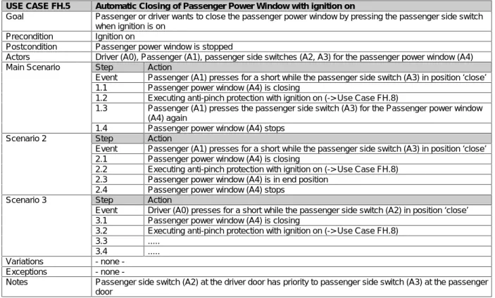
Requirements are gathered with the use case templates introduced in chapter 4.1. The following use case (Figure 11) shows an excerpt from the use case ‘Automatic Closing of Passenger Power Window with ignition on’. For a better understanding, all actors in the use case have been marked with an identifier (Ai) enclosed in the following brackets. Remarkable is also the ‘extends’-relationship of step 1.2 which refines the use case with another use case ‘Executing anti-pinch protection with ignition on’.USE CASE FH.5 Automatic Closing of Passenger Power Window with ignition on
Goal Passenger or driver wants to close the passenger power window by pressing the passenger side switch when ignition is on
Precondition Ignition on
Postcondition Passenger power window is stopped
Actors Driver (A0), Passenger (A1), passenger side switches (A2, A3) for the passenger power window (A4) Main Scenario Step Action
Event Passenger (A1) presses for a short while the passenger side switch (A3) in position ‘close’ 1.1 Passenger power window (A4) is closing
1.2 Executing anti-pinch protection with ignition on (-> Use Case FH.8)
1.3 Passenger (A1) presses the passenger side switch (A3) for the Passenger power window (A4) again
1.4 Passenger power window (A4) stops Scenario 2 Step Action
Event Passenger (A1) presses for a short while the passenger side switch (A3) in position ‘close’ 2.1 Passenger power window (A4) is closing
2.2 Executing anti-pinch protection with ignition on (-> Use Case FH.8) 2.3 Passenger power window (A4) is in end position
2.4 Passenger power window (A4) stops Scenario 3 Step Action
Event Driver (A0) presses for a short while the passenger side switch (A2) in position ‘close’ 3.1 Passenger power window (A4) is closing
3.2 Executing anti-pinch protection with ignition on (-> Use Case FH.8) 3.3 ...
3.4 ... Variations none -Exceptions none
-Notes Passenger side switch (A2) at the driver door has priority to passenger side switch (A3) at the passenger door
5.3 Extracting Requirements Sequence
Diagrams from Use Case Scenarios
Requirements Sequence Diagramclose execute Side switch (A3) Power Window (A4) Anti-Pinch-Protect.(UCFH.8) Passenger (A1) press press stop
Figure 12: Required behaviour in a sequence diagram extracted from the main scenario
The next step in preparing the course-oriented require-ments for the validation of component-based software is the extraction of the requirements sequence diagrams from the use case scenarios. This is done for all meaningful scenarios, variations and exceptions of each use case. The result is a large set of requirements sequence diagrams. Figure 12 shows the requirements sequence diagram extracted from the main scenario of the use case “Automatic Closing of Passenger Power Window with ignition on”. The interactions from the use case main scenario between the actors are described in sequential order. The ‘extends’-use case from step 1.2 becomes a
substitute for an actor in the requirements sequence diagram, because it also interacts with the other actors. To reduce complexity the possible timing requirements are not shown in Figure 12. The time axis would be running top down and temporal constraints would be specified for the execution of single events or between the occurrence of two events (note: the event is just one point without history or future on the time axis but in practise events are associated with actions which consume time).
5.4 Mapping the Requirements Sequence
Diagrams to the Comparison Sequence
Diagrams
Extensive work has to be dedicated to the mapping of the actor identifiers from the use case view to the component identifiers of the component-based simulation model. Actor names are mapped to corresponding component names and event names are mapped to connection-message names of the simulation model as it is shown in Figure 13. The result is the comparison sequence diagram. Finding the corresponding components and connection-messages is a remaining validation task which can not be automated. But after the mapping a computer aided compliance checking against the simulated event traces is feasible.
Actor -> Components: Passenger(A1) -> window_switch Side switch(A3)-> power_window_control Power Window(A4) -> motor Anti-Pinch-Protect.(UCFH.8) -> hallsensor Events -> Connection-Messages press -> AutoUp close -> Close execute -> GetValue stop -> Stop Mapping
Requirements Sequence Diagram
close execute Side switch (A3) Power Window (A4) Anti-Pinch-Protect.(UCFH.8) Passenger (A1) press press stop
Comparison Sequence Diagram AutoUp GetValue motor hallsensor window _switch power_window _control Stop Close AutoUp
Figure 13: Mapping of the requirements sequence diagram to the comparison sequence diagram
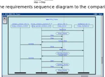
5.5 Simulation based Validation
Validation is done by compliance checking between the comparison sequence diagram (Figure 13) and the simu-lated event trace (Figure 14). Figure 14 shows a recorded event trace sequence diagram which embodies a possible design error because of a differing behaviour. After the initialisation, the ‘window_switch’ component sends an ‘AutoUp’ message to the ‘power_window_control’ com-ponent to assign the ‘motor’ comcom-ponent to ‘Close’ the window. When the ‘window_switch’ component sends the ‘AutoUp’ message again as specified in the use case, the ‘power_window_control’ component sends the wrong message ‘Open’ instead of the required ‘Stop’ to the ‘motor’ component. The logical conclusion is that the ‘power_window_control’ component has either been con-figured wrong or the composition of the components has been made faulty. The component-based model has to be improved.
6.
Conclusions and Further Steps
Component-based software development promises overall improved quality, manageablity and reduced time to mar-ket. It can not be concluded from the quality of single software components to the overall software quality of a composed real-time software. Although errors are limited to composition and configuration errors and the overall number of errors will be less, validation techniques have to be applied for the exposure of design errors. When apply-ing an interface connection architecture and applyapply-ing vali-dated software components in the context of the presented component model, current validation activities may only concentrate on analysing the architecture description. Simulation has been chosen for the validation of the dynamic behaviour of component-based real-time software in an early development phase.
Up to now, the compliance checking between the required and the simulated behaviour is done by hand and its auto-mation is a goal of further research. Extracting scenarios from the structured use cases is simple, but as mentioned before, for real-time systems use cases contain more sce-narios than ordinary transformational software. For that reason, writing a big amount of structured use cases and extracting the requirements sequence diagrams out of it would be more comfortable with tool support. A time-consuming part of the validation process is the mapping of the use case identifiers to the identifiers of the simulation model of the component-based software. This creative step will always need a developer for making the assignments, but it is conceivable to support even that with tool features. Compliance checking between the required comparison sequence diagrams and the recorded event trace sequence
diagrams from the simulation seems to be a feasible task. Deviations of the simulated behaviour from single re-quirements are always indicators for possible composition errors and have finally to be checked by the developer by hand.
7.
Literature
[1] Luckham, D.C. et al.: Specification and Analysis of
System Architecture Using Rapide, IEEE Transactions on
Software Engineering, 21 (4), April 1995, S. 336-355.
[2] Rapide Design Team: Guide to the Rapide 1.0 Language
Reference Manuals, Program Analysis and Verification
Group, Computer Systems Lab., Stanford University, version 1.0, July 1997.
[3] ObjecTime Developer 5.1: User Guide 1.0, ObjecTime
Limited, 340 March Road, Kanata, Ontario, August 1997. [4] Selic, B., Gullekson, G., Ward, P.T.: Real-Time
Object-Oriented Modeling, Wiley, New York, 1994.
[5] Bass, L., Clements, P., Kazman, R.: Software
Architec-ture in Practice, Addison Wesley, Reading, Mass., 1998.
[6] Göhner, Peter: Komponentenbasierte Entwicklung von
Automatisierungssystemen, GMA-Kongreß’98,
VDI-Berichte Nr. 1397, 1998, p. 513-521.
[7] Controller Area Network CAN: An In-Vehicle Serial
Communication Protocol, Handbook, SAE Press, 1992.
[8] Daimler-Benz AG : Presse Information PRI_0428.DOC,
Technologiepressekonferenz, Stuttgart, Sept. 1998. [9] Kytölä, T., Mathony, H.-J., Münich, A.: Objektorientierte
Software-Entwicklung für Karosserieelektronik-Anwendungen, VDI-Tagung ’98 Electronic Systems For Vehicles, VDI-Berichte Nr. 1415, 1998, p. 571-595. [10] Boehm, B. W.: Verifying and Validating Software
Requirements Specifications, IEEE Software Vol. 1, Nr. 1,
Januar 1984, S. 75-88.
[11] IEEE: ANSI/IEEE Std 830-1984, IEEE Guide to Software Requirements Specifications, 1984.
[12] Fleisch, W., Ringler, Th., Belschner, R.: Simulation of
Application Software for a TTP Real-Time Subsystem,
Proc. European Simulation MultiConference, Istanbul, Turkey, 1997, S. 553-558.
[13] Jacobsen, Ivar et al.: Object-Oriented Software
Engi-neering: A Use Case Driven Approach, Addison-Wesley,
Reading, Mass., 1992.
[14] Fleisch, Wolfgang: Validierung komponentenbasierter
Software für eingebettete Echtzeitsysteme,
GMA-Kongreß’98, VDI-Berichte Nr. 1397, 1998, p. 539-546. [15] Mattingly, LeRoy, Rao, Harsha: Writing Effective Use
Cases and Introducing Collaboration Cases ,The Journal
of Object-Oriented Programming, Vol. 11(6), 1998, p.77-87.
[16] Cockburn, Alistair: Structuring Use Cases with Goals, The Journal of Object-Oriented Programming, Vol. 10 (5/6), Sept.-Dec. 1997.
[17] Unified Modeling Language - UML - Notation Guide
version 1.1, Rational Software Corporation, Santa Clara,