REAL-TIME OPEN SOURCE TRAFFIC CONTROL SOFTWARE FOR THE ADVANCE TRAFFIC CONTROLLER
by
JUSTIN LOGAN KEY
B.S. University of Central Florida, 2004 M.S. University of Central Florida, 2005
A dissertation submitted in partial fulfillment of the requirements for the degree of Doctor of Philosophy
in the College of Graduate Studies at the University of Central Florida
Orlando, Florida
Fall Term 2012
ii
ABSTRACT
Under the initiative of Department of Transportation (DOT) a safety-critical, dual redundant, open source traffic signal control application is currently being developed. The system named SCOPE, for Signal Control Program Environment, currently implements standard 8-phase NEMA logic and the National Cooperative Highway Research Program 3-66 preemption logic. SCOPE is designed to be part of the Advanced Traffic Controller (ATC), making use of API standard 2.06b to integrate with the hardware. Safety-critical status is achieved through redundancy of application logic that constantly compares expected signal phase information. From baseline requirements, engineers independently program application code, one using Ada95 and the other using C++.
The Traffic EXperimental Analytical Simulation Model, a microscopic single-intersection vehicular simulation, was used for initial validation and testing of the functionality of the system. The second demonstration of the SCOPE, used actuated detector data collected from a recording of a live
intersection. Actuator calls were placed on SCOPE at the same times the vehicles triggered the detectors in the video (assuming the vehicles were not in-queue). Using SCOPE the real-world traffic was not only right-of-way safely yielded, but the traffic flow state time average time in-queue reduced. The final phase of testing will occur when the DOT performs Formal Qualification Testing, which is scheduled for 2013. Upon validation and subsequent release to the open source community SCOPE will provide users the ability to replace the proprietary application software residing in ATC cabinets. Transparency will be provided into another aspect of the traffic control signal thus taking the initiative of ATC one step further.
iii
This dissertation is dedicated to my parents for their love and support throughout my education and my life and to my fiancé for her love and support throughout my Ph.D. studies.
iv
TABLE OF CONTENTS
LIST OF FIGURES ... vii
LIST OF TABLES... ix
CHAPTER ONE: INTRODUCTION ... 1
Traffic Control Signal Definition ... 1
Need for Traffic Control Signals ... 3
CHAPTER TWO: LETRITURE REVIEW ... 7
Recent Strides for Controller Openness ... 7
Need for Redundant Traffic Control Signal Software ... 8
Safety Critical Software ... 8
Creating Safety Critical Software ... 9
N-Version Programming ... 9
Recovery Block / Consensus Recovery Block ... 11
Signal Timing ... 12
Definitions and Terminology ... 12
Ring And Barrier Structure ... 15
Actuated Control ... 16
Actuated Control Parameters ... 18
TS2 Cabinets ... 19
Evaluation of Existing Traffic Signal Control Programs ... 20
Summary of Criteria ... 21
Program 1 - California Partners for Advanced Transit and Highways (PATH) ... 22
Program 2 - ATI Dual Redundant Base Software ... 24
Program 3 - The InSync Adaptive Traffic Signal Controller ... 27
Program 4 – MIT Intelligent Transportation System Program (MITSIMLab) ... 27
Program 5 – Software Controller Interface Device (CID) II ... 29
Summary of Research Findings (Pros and Cons) ... 30
Software Selection for Phase II ... 32
CHAPTER THREE: RESEARCH OBJECTIVES AND METHODOLOGY ... 33
Research Objectives And Methodology ... 33
v
CHAPTER FOUR: SOFTWARE DESIGN ... 38
Software Description ... 38
Ada95/C++ Communication & Synchronization... 39
Preemption Design ... 40
ATC Integration ... 41
Interface to Primary Software ... 42
Primary / Secondary Command Names and Values ... 43
Data sent from the Primary to the Secondary ... 43
Data sent from the Secondary to the Primary ... 57
Data sent from the Primary to the GUI ... 59
Data sent from the GUI to the Primary ... 61
TEXAS Model Interface ... 62
CHAPTER FIVE: SOFTWARE TEST ... 65
Test & Validation Considerations ... 65
Tools & Methods ... 66
Testing with Traffic Simulator ... 66
Integrating with Peek ATC-1000 ... 69
Formal Qualification Testing ... 72
CHAPTER SIX: RESEARCH METHODOLOGY ... 75
Experiment Definition ... 76
Hypotheses ... 76
Existing System / Live Intersection ... 77
Comparison to SCOPE ... 77 Experiment Design ... 78 Assumptions/ Estimation ... 79 Data Collection ... 82 Detectors ... 84 Data Extraction ... 86 Data Preparation ... 87 Data Analysis ... 88 Simulation... 90
vi
CHAPTER SEVEN: ANALYSIS AND RESULTS ... 93
Gemini Boulevard & Plaza Drive ... 93
Simulation... 95
Minimum Recall ... 96
Maximum Recall ... 98
Max Out ... 100
Gap Out ... 102
CHAPTER EIGHT: CONCLUSION ... 106
CHAPTER TEN: FUTURE WORK ... 108
APPENDIX A: INDUSTRY INTEREST IN RESEARCH ... 110
Industry Interest In Research... 111
APPENDIX B: UML DIAGRAMS ... 113
Unified Modeling Language (UML) ... 114
Class Diagram ... 114
Class Operations And Attributes ... 115
Sequence Flow ... 120
Initialization ... 120
Incoming Message... 121
Incoming Time ... 121
APPENDIX C: LIVE DATA CAPTURE ... 123
APPENDIX D: LIVE DATA CAPTURE ... 133
Lane 6 Time In-Queue (249 Vehicles) ... 134
Lane 2 Time In-Queue (201 Vehicles) ... 135
Lane 8 Time In-Queue (78 Vehicles) ... 136
Lane 4 Time In-Queue (57 Vehicles) ... 137
vii
LIST OF FIGURES
Figure 1: N-Version Programming ... 11
Figure 2: (a) Phasing Diagram (b) Movement Diagram ... 13
Figure 3: (a) Phase Pair Diagram (b) Ring And Barrier Diagram ... 15
Figure 4: Actuated Interval Concept ... 17
Figure 5: Overview of ATC using SCOPE Application ... 39
Figure 6: Optimal SCOPE System Overview. ... 41
Figure 7: Data Flow Diagram ... 42
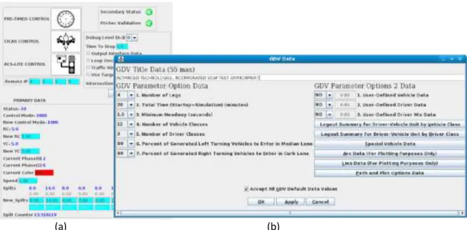
Figure 8. (a) Original Stand Alone GUI designed for SCOPE. (b)TEXAS Model Interface Panel. ... 67
Figure 9. TEXAS Model Modified to use SCOPE. ... 68
Figure 10. (a) 4 Legged. (b) Y shaped 3 Legged. (c) TEXAS Diamond. ... 69
Figure 11. (a) SCOPE Running on Peek ATC communicating with Android Phone App. (b) VC 3500 Virtual Cabinet Interface. ... 70
Figure 12: Android Tablet App Startup Screen ... 70
Figure 13: Android Tablet App Pre-timed Status Screen ... 71
Figure 14: Android Tablet App Settings Screen ... 71
Figure 15: TFHRC Test Site ... 73
Figure 16: PATH Test Site ... 74
Figure 17: Simulation Flowchart for In-Queue Time Per Lane ... 79
Figure 18: Dilemma Zone for 35 mi/h approach (representative of Gemini Blvd) ... 81
Figure 19: Frame of Video Capture from Intersection ... 82
Figure 20: (left) Map of Intersection. (right)Signal at Intersection. ... 83
Figure 21: Idaho Transportation Department Suggested Detector Placement ... 84
Figure 22: Example Simulator Format Data File ... 88
Figure 23: Flow Rates per Lane During Peak Hour ... 90
Figure 24: (Top) Actuated Call Interface (Bottom) Pedestrian Call Interface ... 91
Figure 25: (Top) Simulation Visualization (Bottom) Main Console ... 92
Figure 26: Actuated Parameters for Run #4 ... 97
viii
Figure 28: Actuated Parameters for Run #3 ... 99
Figure 29: Actuated Parameters for Run #4 ... 99
Figure 30: Actuated Parameters for Run #5 ... 101
Figure 31: Actuated Parameters for Run #6 ... 102
Figure 32: Actuated Parameters for Run #7 ... 104
Figure 33: Actuated Parameters for Run #8 ... 105
Figure 34: NTCIP Framework ... 108
ix
LIST OF TABLES
Table 1: Requirements applicable to secondary software for SCOPE project ... 36
Table 2: Derived requirements for completing research objectives ... 37
Table 3: Commands ... 43
Table 4: Sending Time Structure ... 44
Table 5: Send Results Structure ... 44
Table 6: Change Clear Time Structure ... 45
Table 7 : Change Split Time Structure ... 45
Table 8: Change Mode Structure ... 46
Table 9: Preempt Command Structure ... 47
Table 10: Set Minimum Green Time Structure ... 47
Table 11: Max Green Original Value Structure ... 48
Table 12: True Max Time Structure ... 49
Table 13: Extension Time Structure ... 49
Table 14: Consecutive Failure Constant Structure ... 51
Table 15 : Adjustment Structure ... 51
Table 16: Actuated Trigger structure ... 52
Table 17: Recall Mode structure ... 53
Table 18: Gap Time structure ... 53
Table 19: Time Before Reduction structure ... 54
Table 20 : Time To Reduce structure ... 54
Table 21: Minimum Gap Time structure ... 55
Table 22: Send Sync Structure ... 55
Table 23: Debug Level Structure ... 57
Table 24 : Heartbeat Structure ... 57
Table 25: Secondary State Structure ... 58
Table 26: GUI Display Data Structure ... 60
Table 27: GUI To Primary Data Structure ... 61
x
Table 29: SCOPE To TEXAS Model Structure... 64
Table 30: Dilemma Zone – Probability of Stopping ... 80
Table 31: FHWA Traffic Detector Handbook Suggested Detector Placement ... 85
Table 32: Example Data File ... 88
Table 33: Percentage of Vehicles Stopped Per Lane ... 94
Table 34: Average Time In-Queue for Vehicles Stopped Per Lane ... 94
Table 35: Average Time Per Lane & Total Time of Vehicles In-Queue at Gemini/Plaza ... 95
Table 36: Average Time Per Lane & Total Time of Vehicles In-Queue Using Simulation with Minimum Recall Mode (Left) Run #1 (Right) Run #2 ... 97
Table 37: Average Time Per Lane & Total Time of Vehicles In-Queue Using Simulation with Maximum Recall Mode (Left) Run #3 (Right) Run #4 ... 100
Table 38: Average Time Per Lane & Total Time of Vehicles In-Queue Using Simulation with Max Out Mode (Left) Run #5 (Right) Run #6 ... 102
Table 39: Average Time Per Lane & Total Time of Vehicles In-Queue Using Simulation with Gap Out Mode (Left) Run #7 (Right) Run #8 ... 105
1
CHAPTER ONE: INTRODUCTION
Under the initiative of U.S. Department of Transportation a safety-critical, dual redundant, open source traffic signal control application is currently being developed. The system named SCOPE, for Signal Control Program Environment, currently implements standard 8-phase NEMA logic and some concept of the National Cooperative Highway Research Program 3-66. SCOPE is designed to be part of the
Advanced Traffic Controller (ATC), making use of API standard 2.06b to integrate with the hardware. In addition to executing on the ATC platform, SCOPE can run on desktop workstations and PowerPC Linux based prototype boards. It is easily ported to any CPU. Safety-critical status is achieved through redundancy of application logic that constantly compares expected signal phase information. From baseline requirements, engineers independently program application code, one using the strongly typed Ada95 which is popular for mission critical systems and the other using the statically typed C++ which is popular for embedded systems. The Traffic EXperimental Analytical Simulation (TEXAS) Model is currently used for validation and testing with Formal Qualification Testing to occur late in 2011. Upon validation and subsequent release to the open source community SCOPE will provide users the ability to replace the proprietary application software residing in ATC cabinets. Transparency will be provided into another aspect of the traffic control signal thus taking the initiative of ATC one step further.
Traffic Control Signal Definition
Traffic signal controllers are a signaling mechanism positioned at road intersections and pedestrian crosswalks to control competing flows of traffic and ensure that conflicting or dangerous traffic signals are not permitted. They are responsible for synchronizing solid-state lamp switching of any number of traffic lights, also known as traffic signals, and stop lights in an area. Virtually everyone in every city in
2
the developed world places their own and their passengers' physical safety in a signal's allocation of right-of-way. When properly implemented, traffic signal controllers provide significant decreases in travel time, fuel consumption, and emissions, as well as some increases in safety.
The operation of a traffic signal controller can be described in terms of cycle length, signal phases, offsets, scope and mode. The cycle length is the total time required to complete one sequence of signal phases, and it typically lasts 60 to 120 seconds for a four-legged intersection. A phasing plan defines when a traffic signal changes states. The offset between successive traffic signals is the difference in time between the start of their respective green light states. The scope is the level of interaction the traffic signal controller has with other controllers, for this research the focus will only be on:
Individual Intersection Control – A single traffic signal operates without affecting the operation of other traffic signals.
Finally traffic signal controllers are categorized by their individual mode of operation, for an individual intersection the operations include:
Pre-timed – The controller sets signal phases and the cycle length based on a predetermined schedule which is created from historical data.
Actuated – Cycle length and phases can be adjusted, with possibility of some phases being skipped, based on traffic flow. The green time for is a function of the traffic flow that can be varied between minimum and maximum lengths.
3
minor street detector and is best suited for locations with low volume minor street traffic.
Full Actuated - All approaches to an intersection have detectors and assignments of the right of way are made in accordance with traffic demand. This control is best where the demand proportions from each leg of the intersection are less predictable.
Traffic Responsive – A signal, or group of signals, use inputs from detectors to chose an appropriate timing scheme from a library of different schemes. Libraries can be selected based on various data analyzing procedures, whether it is current or future prediction, pattern matching of traffic patterns.
Adaptive Control Strategies (ACS) - The most advanced traffic signals, they receive real-time data through detectors to create a timing plan. No library of timing plans is needed, which is ideal for areas with high rates of growth, where libraries would be outdated frequently.
Need for Traffic Control Signals
As the population continues to grow, the demand on the existing transportation infrastructure will become increasingly hard to meet. With roads and highways unlikely to keep pace due to cost and dwindling land supply, the use of traffic control signals will be critical to operating our current roadway systems at maximum capacity. Traffic signals generally provide the greatest payoff for reducing surface street congestion when compared with other methods, such as widening roads (1). These devices can help ease congestion without the cost and environmental impact of road expansion. When properly implemented, traffic signal controllers provide significant decreases in travel time and fuel consumption. These decreases provide a great cost and environmental benefit, as the fuel consumed by vehicles stopping and idling accounts for approximately 40% of network wide vehicular fuel consumption (2).
4
When a traffic control signal is properly timed, it is invaluable for safety of motorists and pedestrians. In particular, signals reduce high-fatality rate accidents such as motorist-pedestrian and right angle (T-bone) collisions (3).
As beneficial as properly placed and maintained traffic control signal can be, an unwarranted or improper timed signal can lead to just the opposite effects. Increases in accident frequency, fuel consumption, delay, disobedience of signals, and use of inadequate alternate routes are all consequences of poor timing (4). Once installed traffic control signals are given little thought, and are often ignored unless citizens complain about their operation. Under normal circumstances new installations, maintenance, and retiming activities are often delayed or canceled due to budget issues. The current economic situation faced by many local governments only amplifies this problem. In fact, more than half of the signals in North America are in need of repair, replacement, or upgrading (4).
Many of the nation’s signals in need of repair could be improved by updating equipment or by simply adjusting and updating timing plans (5). Many agencies have no program for monitoring the applicability of signal timing plans to the current traffic patterns, and it is not uncommon to find agencies that have not re-timed coordinated signals for five years (6). However for the vast majority of signals a paradigm change to a modern advance controller would yield the greatest benefit. Despite a slow start, computer models have begun replacing manual settings and optimization of signal timing plans. These powerful models use historical data and computer simulation to create an optimal signal timing plan that either maximizes bandwidth or minimizes total delay. Today’s traffic signal control varies in complexity, from simple systems that use pre-timed plans based on historical data, to adaptive, also known as advanced, signal control which optimize in real-time plans for a network of signals according to traffic conditions.
5
While pre-timed signal plans are expensive to prepare and keep up to date (7), moving to a more advanced signal controller scheme is not without expense either. These signals incur a higher up-front cost, and while the maintenance cost may be reduced, proper maintenance is still required. For new signals, local governments are faced with the dilemma of whether or not to stretch their budget to invest in the more expensive system. While officials may understand new signals will save them money in the long run, justifying the cost to citizens and their current year’s budget might not be an easy task. For locations with existing infrastructure the dilemma can be even greater, should they remove the old system or hang on to what they have?
No matter what equipment or design decisions are chosen, upgrading a traffic control system has a hefty price tag. The process cannot be done without thorough studies and planning by a qualified traffic engineer. However, the cost associated with signal installation and improvement doesn’t have to be as great as it is today. Most traffic signals are proprietary, sole-source acquisitions which tie local governments into long-term contracts. The equipment and contracts have inflated costs, promote non-competitive business tactics, and requires use of their product for future installations. These “tie-in” sales practices have led to litigation, calls for non-proprietary industry standards, and the creation of in-house systems(8)(9)(10).
In addition to inflated costs that proprietary software tends to incur, there also exist problems with the proprietary nature of the software performance data. Statistics such as the number of software faults and conflicting traffic signals are not made public. Conflict Management Units (CMUs) are system-independent electronic devices attached to traffic signal controllers that prevent conflicting signals from being displayed. To the average citizen, CMUs cause the blinking “all-red” signal, that they see every
6
once in a while when the traffic signal is out. While CMUs prevent accidents from occurring, they provide little insight into the software logic causing the failure. That data remains property of provider, and while the CMU makes the system safety-critical the software is not.
7
CHAPTER TWO: LETRITURE REVIEW
Recent Strides for Controller Openness
In 2000 when the city of New York went to upgrade their aging traffic control signals they made sure to protect the interests of the City over the long term. Having begun to upgrade their system in the past and stopped due to ballooning costs they knew not to repeat their mistakes. This time the vendor was required to provide the source code and a full development system. All equipment had to adopt the National Transportation Communications for ITS Protocol (NTCIP) standards for actuated signal control, no "custom" (or semi-custom) implementations of NTCIP would be allowed. The City and subsequent third parties were allowed to make modifications to the software. Ownership of the software was left to the vendor; license rights allowed the City to deploy the software or derivative products at all intersections within the City. While making a significant push for openness in software, the solution fell short on adhering to a standard on the controller front. The city, “decided that the 2070 construct (with all internally interchangeable modules) was too expensive for the relatively simple intersections within the City.” (8) They mandated a functional and size compatible solution, but the internal construction, including the processor and memory, was left to the vendor.
In 2004 the State Attorney General Bill Lockyer filed an antitrust lawsuit against Econolite Control Products claiming that the “tie-in” sales practice of traffic signal equipment was illegal. The lawsuit stated Econolite was forcing contractors bidding on public projects to buy certain equipment at inflated prices as a condition for using other "proprietary" equipment which only the company can provide and this had cost Southern California taxpayers millions of dollars (10). A spokesman for Lockyer’s office stated, “when electrical contractors pay inflated prices…they are passed on to the taxpayers. Primarily what we're looking at is to make sure that these guys stop so that taxpayers don't get stuck with the
8
tab." (10) According to the lawsuit the use of the Econolite signal controller required use of Econolite signal lights and preemption systems that may have been purchased elsewhere for less. In 2006, a court agreed and found Econolite liable for the use of “tie-in” sales practices (11).
Need for Redundant Traffic Control Signal Software
Present day traffic control systems are essentially ancillary in nature, i.e. they do not directly control the motorist but simply provide indication (12). However a faulty indication, as say with conflicting green signals, could easily cause a hazard resulting in any combination of property damage, serious injury, or death. The traffic signal’s ability to provide control or mitigation of hazards is the reason it is considered safety-critical. For many safety critical systems, redundancy is the only acceptable method to achieve high operational reliability (13), yet the capabilities of existing traffic controllers do not include software redundancy.
Safety Critical Software
Medical devices, aircraft flight control, weapons, and nuclear reactors are common examples of safety-critical software as their failure would most likely directly lead to the loss of human life. However some examples may be less obvious, from out of order traffic lights that contribute to individuals being
involved in an accident, to structural engineering design tools whose fault leads to a building collapse, to a bug in the compiler used in the create another piece of safety-critical code. A safety-critical system is simply any system whose failure could result in loss of life, significant property damage, or damage to the environment (14). Simply put safety-critical software must be reliable because someone’s life depends on it.
9
Creating Safety Critical Software
The usual method to attain reliability of software operation is fault-avoidance (or intolerance) (15). This simply means that all defects are eliminated prior to the software being fielded. However in most software the elimination of all defects is never attained and a crash or an erroneous result is inevitable. This observation leads to the conjecture that for reliable software operation, redundant software in some form is required to detect, to isolate, or recover from effects of undetected software defects (16). Three important methods of creating fault-tolerant software systems have been developed, namely N-Version Programming, Recovery Block, and Consensus Recovery Block (13). For all these methods, increasing the redundancy, within the software system is essential.
N-Version Programming
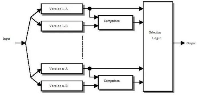
N-version programming (NVP) is defined as the independent generation of N>2 functionally equivalent programs from the same initial specification. More simply stated, NVP is a method or process in software engineering where multiple functionally equivalent programs are independently generated from the same initial specifications (17). The major objectives of the NVP process are to maximize the independence of version development and to employ design diversity in order to minimize the probability that two or more member versions will produce similar erroneous results that coincide in time for a decision (consensus) action (18). In turn the result is more reliable software operation due to built-in fault tolerance and redundancy.
In general the steps of N-version programming are:
Creation of an initial specification of the presenting the functional requirements of the software being developed. The specification should unambiguously define (17):
10
1. the function to be implemented by an N-version software unit;
2. data formats for the special mechanisms: comparison vectors (“c-vectors"), comparison status indicators (“cs-indicators"), and synchronization mechanisms
3. the cross-check points (“cc-points") for c-vector generation; 4. the comparison (matching or voting) algorithm; and
5. the response to the possible outcomes of matching or voting
Using the specifications, two or more versions of the program are independently developed, each by a group that does not interact with the others. Whenever possible the implementations of these functionally equivalent programs use different algorithms and programming languages (13).
Some N-version execution environment (NVX) is developed which runs the N-version software and makes final decisions of the N-version programs as a whole given the output of each individual N-version program (13).
11
Figure 1: N-Version Programming
Recovery Block / Consensus Recovery Block
The Consensus Recovery Blocks approach combines N-Version Programming and Recovery Blocks to improve the reliability over that achievable by using just one of the approaches. Acceptance tests in the Recovery Blocks suffer from lack of guidelines for their development and a general proneness to design faults due to the inherent difficulty in creating effective tests. The use of voters as in N-Version Programming may not be appropriate in all situations, especially when multiple correct outputs are possible (13). Consensus Recovery Blocks uses a decision algorithm similar to N-Version Programming as a first layer of decision and a second layer using acceptance tests (Recovery Blocks). Although more complex than either of the individual techniques, the this combined approach, if properly implemented, can result in more reliable results.
12
Signal Timing
Definitions and Terminology
Traffic signal controllers implement a timing plan that consists of a pre-timed or actuated mode, or a combination of the two. A pre-timed controller has a predetermined and fixed cycle length, phase plan, and phase times. This makes coordinating with adjacent pre-timed signals easy, since the start and end of green are predictable. Pre-timed control is ideally suited to closely spaced intersections where traffic volumes and patterns are consistent on a daily or day-of-week basis. Such conditions are often found in downtown areas. They are also better suited to intersections where three or fewer phases are needed (19). For an actuated controller cycle length, phase plan and phase times are controlled by detector actuations. Phasing represents the fundamental method by which a traffic signal accommodates the various users at an intersection in a safe and efficient manner.
Many of the terms used to describe pre-timed and actuated control are often used incorrectly by professionals or publications (20). The Signal Timing Manual uses the following terminology when describing signal control:
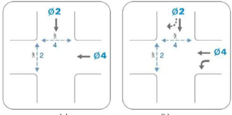
Phase – the total of the green, red and yellow interval for a given movement(s) (Figure 2a). Split – The time assigned to a phase (green and the greater of the yellow plus all-red or the pedestrian walk and clearance times) during coordinated operations. May be expressed in seconds or percent.
Movement – describes the user type (vehicle or pedestrian) and action (turning movement) at an intersection. Two different types of movements include those that have the right of way and
13
those that must yield consistent with the rules of the road or the Uniform Vehicle Code (Figure 2b).
(a) (b)
Figure 2: (a) Phasing Diagram (b) Movement Diagram
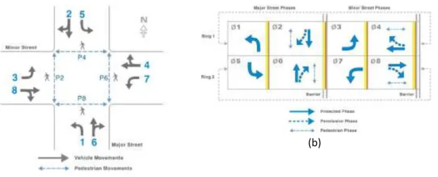
Phase Pair – A combination of two phases allowed within the same ring and between the same
barriers. For example phase pair 1&2 can operate concurrently with 5&6, and 3&4 can operate concurrently with 7+8 (Figure 3a).
Ring – A series of conflicting phases that operate in sequence.
Barrier - A separation of intersecting movements in separate rings to prevent operating conflicting phases at the same time.
and the following terms when describing actuated control:
Minimum Gap - A volume density parameter that specifies the minimum green extension when
gap reduction is used.
Minimum Green - A parameter that defines the shortest allowable duration of the green interval.
14
Extend - A detector parameter that increases the duration of a detector actuation by a defined fixed amount.
Gap Out - A type of actuated operation for a given phase where the phase terminates due to a lack of vehicle calls within a specific period of time (passage time).
Max Out - A type of actuated operation for a given phase where the phase terminates due to reaching the designated maximum green time for the phase.
Queue -A line of vehicles, bicycles, or persons waiting to be served by a phase in which the flow rate from the front of the queue determines the average speed within the queue. Slowly moving vehicles or people joining the rear of the queue are usually considered part of the queue.
Call - An indication within a controller that a vehicle or pedestrian is awaiting service from a particular phase or that a recall has been placed on the phase.
Recall - A call is placed for a specified phase each time the controller is servicing a conflicting phase. This will ensure that the specified phase will be serviced again. Types of recall include soft, minimum, maximum, and pedestrian.
Minimum Recall - A parameter which results in a phase being called and timed for at least its minimum green time whether or not a vehicle is present.
Maximum Recall - The maximum recall parameter causes the controller to place a continuous
call for vehicle service on the phase. It results in the presentation of the green indication for its maximum duration every cycle as defined by the maximum green parameter for the phase. When the maximum recall parameter is selected for a phase, the maximum green timer begins timing at the beginning of the phase’s green interval, regardless of the presence of a conflicting call or lack thereof.
15
(a)(b)
Figure 3: (a) Phase Pair Diagram (b) Ring And Barrier Diagram
Ring And Barrier Structure
The modern U.S. practice groups phases into a continuous loop (or ring) and separates the crossing or conflicting traffic streams with time between when they are allowed to operate (20). By making movements sequential or adding a barrier between the movements conflicting phases are avoided. In Figure 3b a dual ring controller, which uses a maximum of eight phases (or traffic control lights) to accommodate the eight movements. Ring 1 contains phases 1 through 4, and ring 2 contains phases 5 through 8. The two rings operate independently, except that their control must cross the “barrier” at the same time (20). The barrier separates the east-west movements from the north-south movements so as to operate without giving the right-of-way to conflicting movements at the same time. This allows phase pair 1 and 2 can operate concurrently with phase pair 5+6. Phase pair 3+4 can operate
concurrently with phase pair 7+8. These phase pairs are also known as concurrency groups because they can time together.
16
Actuated ControlResearch has shown that the best form of isolated operation occurs when fully-actuated controllers are used. Actuated controllers operate most effectively when timed in a manner that permits them to respond rapidly to fluctuations in vehicle demand (21). Basic actuated control relies on the phasing parameters that change in accordance with sensor inputs. The minimum green time attempts to allocate just enough time for stopped vehicles to partially cross the intersection or pedestrians to cross the street. One method that can be used to calculate the minimum green is:
Minimum Green = 5 + 2n Where:
n is the number of vehicles that can be stored between the stop line and the far detector in one lane. This is determined by dividing the distance (in feet) between the stop line and the detector by 25, since 25 is the average vehicle length plus stopped-headway in feet (22).
Each vehicle requires enough green time to travel from the detector to the intersection. This is referred to as passage time, vehicle extension, or gap. Gap refers to the distance between vehicles as well as the time between vehicles. Each successive vehicle actuation increases the phase green time and when no opposing calls exist, the controller rests. Extensions continue to be timed, but with no effect on the green interval. Passage time is calculated as follows:
Passage Time = D / S Where:
D is the distance from the stop line to the detector in feet.
17
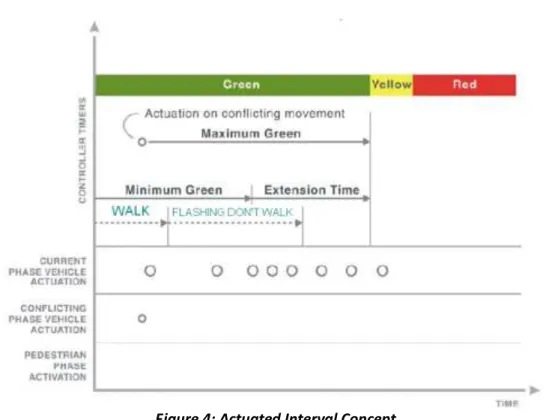
When opposing traffic does exist, the maximum time the green interval can be extended is referred to as the maximum green time (Figure 4).
Figure 4: Actuated Interval Concept
When actuation is triggered from another phase, the maximum green timer is started. The current green will be held until the time between actuations is greater than the preset unit extension or gap. If a gap is detected, the yellow change interval will begin and the controller will transition to the next phase in sequence. If the change to the next phase is due to detection of a gap it is referred to as a gap-out, if it is due to the maximum green time being reached it is referred to as termination by maximum green or max-out.
At the completion of the green interval, the yellow interval begins. The yellow signal alerts drivers that the red signals is imminent and proceed if too close to stop other to stop. The following equation is generally used to determine the proper change interval:
18
Yellow Time = t + S / (2a +- 64.4 g)Where:
t is the perception/reaction time of the driver in seconds (typically 1.0 second).
S is the speed on the approach in feet per second.
a is the deceleration rate in feet per second (typically taken as 10 feet per second squared).
g = approach grade, percent of grade divided by 100 (add for up-grade and subtract for downgrade) (22).
The all-red interval follows the yellow interval, and gives vehicles in the intersection time to clear before conflicting lanes are given right of way. It is common for the all-red interval to be one to two seconds, but on slower speed approaches, it is not unusual to use a very short duration of 0.0 to 0.5 seconds.
Red Time = (W + L) / S
Where:
W is the Width of intersection in feet.
L is the length of vehicle in feet (typically taken as 20 feet).
S is the speed on the approach in feet per second (22).
Actuated Control Parameters
19
used (20). Phase recall, passage time, simultaneous gap, and dual entry are all common parameters used when designing an actuated controller. A recall places a call for a conflicting phase, whether there are any detector triggered calls for that phase. According to the NTCIP these phase option parameters have four variations: minimum recall (also known as vehicle recall), maximum recall, pedestrian recall, and soft recall (23).
The most commonly used recall mode is minimum recall, and it is timed for at least the minimum green whether a detector has been triggered or not. The call is cleared upon start of green for the affected phase and placed upon start of the yellow change interval. It is frequently used to give major road traffic the right-of-way regardless of demand on minor roads. Maximum recall places a continuous call on the phase, resulting in the maximum green time. The maximum recall is desirable if a fixed-time operation is desired, detectors are not used or out of service or , or left-turns are associated with thru traffic and gap-out is not desired. Similarly for pedestrian recall, a continuous call is placed for pedestrian service on the phase. The use of the pedestrian recall is applicable when pedestrian detection is not used or out of service, or there is high pedestrian traffic. The soft recall parameter places a call on the phase in the absence of a serviceable conflicting call, resulting in the minimum green time being used. The use of soft recall is applicable when there is a desire to give major-road green time when demand for the conflicting phases is absent.
TS2 Cabinets
The National Electrical Manufacturers Association (NEMA) standardizes equipment used to facilitate and expedite the safe movement of pedestrians and vehicular traffic. As new technologies become available they seek industry help in developing these standards to accommodate technology advances and new
20
incorporate standard practices. The NEMA Standards Publications define three major specifications for a traffic controller. These specifications include environmental (i.e., temperature, shock, etc.), traffic control logic (i.e,. phases, rings, safety, etc.) and the cabinet interface (i.e., A, B, C connectors and BIU SDLC interface).
Most jurisdictions use NEMA TS-1 and TS-2 or Model 170 actuated controllers (22), with TS2 being the newest standard. TS2 specifies controllers and cabinets more fully than the TS1 or 170/179 standards by covering auxiliary functions. These auxiliary functions include coordination of multiple intersections, preemption for emergency vehicles or trains, time-based control which varies signal coordination throughout the day, and an automatic flash triggered by a manual switch, time switch or system
command. It also assures safer operation and enhanced diagnostics when compared to the older TS1 or 170/179 standards (24). However, The TS2 lacks requirements that enable interchangeability of sub-components or software between controllers form different manufacturers (FHWA Traffic control system handbook 2005). The TS2 standards assume that the whole controller will be replaced when the system changes. Controllers that follow the TS 2 standards are called NEMA controllers and the
manufacturer provide the software along with the controller. TS2 controllers offer more flexibility in assigning traffic signal phases in order to control many complex or unique situations. There are four timing rings, up to sixteen vehicle and pedestrian phases, and each phase can be assigned to any ring (25).
Evaluation of Existing Traffic Signal Control Programs
Programs were considered to serve as the core of SCOPE and complexity metrics analysis was used to determine their suitability. McCabe metric analysis was chosen over Halstead methods because of the
21
availability of free analysis tools. A structured software procedure, method, or function should have a McCabe Cyclomatic complexity of less than or equal to 12 (McCabe suggests 10, other projectshave been very successful using a limit of 15). The McCabe complexity is a measure of quantity, where calculations measure the number of linearly independent paths through a program's source code. Another type of metric analysis is Essential Complexity which measures the “quality” of a software system. It is
calculated by removing all primitives from a procedure's control flow and then computing the Cyclomatic complexity on what remains. There is no magic number for Essential Complexity.
Summary of Criteria
Although the requirements of the project have changed since the project began, the open source programs where analyzed using the following criteria:
1. Can it be ported to an Advanced Traffic Controller Architecture?
2. Can NCHRP 3-66 concepts be incorporated?
3. Can it be interfaced to CICAS? 4. Can it be interfaced to ACS Lite? 5. Does it have a default steady state? 6. Is the software well documented? 7. Does it make use of exception handling?
8. Does its McCabe Cyclomatic complexity fall within the recommend value of less than or equal to 12?
9. What is its Essential Complexity and how does that compare to others under analysis? 10.Is the nesting level of loops reasonable?
22
Program 1 - California Partners for Advanced Transit and Highways (PATH)
Dr. Marco Zennaro developed the Berkeley Adaptive Traffic Control System Protocol (Berkeley
ATCP2070) at the University of California Berkeley. It was developed specifically for the Econolite Model 2070 Advanced Traffic Controller. It was released under GPLv2 in May of 2008 and its current (and only) version is 1.0. According to Dr. Zennaro, it is meant to provide interoperability and scalability.
Unfortunately, only the “core” program (batcp.cpp) was available. The core program includes several C++ header files (such as modes.h, types.h, signal.h, and process.h) which are needed for compilation. In addition, the batcp.cpp is coupled to the operating system (OS9) through the include of OS9def.h.
Base Evaluation Criteria
Can it be ported to an Advanced Traffic Controller Architecture?
YES. It already runs on an Advanced Traffic Controller. It is not running under Linux but can be ported.
• Can NCHRP 3-66 concepts be incorporated?
YES, but not easily done. The application software is a single file, batcp.cpp. • Can it be interfaced to CICAS?
YES. but not easily done. See above (single file problem). • Can it be interfaced to ACS Lite?
YES. but not easily done. Same as above (single file problem). • Does it have a default steady state?
YES.
• Is the software well documented?
23
• Does it make use of exception handling?NO. There are zero exception handlers. Errors are not caught which could lead to software crashes. • Does its McCabe Cyclomatic complexity of fall within the recommend value of less than or equal
to 12?
NO. The McCabe Cyclomatic complexity for the PATH software averaged 19.94.
• Does its McCabe Essential Cyclomatic complexity fall within the recommend value of of less than or equal to 12?
NOT PERFORMED. The free tool used to perform metric analysis on the PATH program did not contain an essential cyclomatic function.
• Is the nesting level of loops reasonable?
YES . Hand inspection of the software showed no nested looping. • Is the error diagnostic system comprehensive and straight forward?
NO. There is no diagnostic error system.
Additional Criteria from SCOPE requirements
• Is the software Open Source?
YES. It is released under GPLv2
• Does it already contain or use industry standard NTCIP protocols?
NO. But they can be added (again, not easily)
• Can it be integrated or is it integrated with the TEXAS Mode, a single-intersection vehicular traffic simulation, to validate the results?
24
YES. Before it is integrated into the TEXAS Model, each procedure in the program would have to be broken out into separate modules. The program does not make use of any object oriented attributes (inheritance, dynamic polymorphism, encapsulation, etc). The program would need to be re-designed and an interface to the TEXAS Model added.
• Can it be integrated with CORSIM?
YES. Last response applies here also.
Program 2 - ATI Dual Redundant Base Software
Advanced Technologies, Incorporated (ATI) developed a dual redundant base traffic intersection
controller prototype as part of the Phase I effort for 06-FH1. This prototype could control an intersection and contained the railroad preemption concept of NCHRP 3-66. The prototype used a configuration file to “define” the intersection. The number of intersection approaches, traffic signals, lanes, and crosswalks are all modifiable without software constraints.
Base Evaluation Criteria
Can it be ported to an Advanced Traffic Controller Architecture?
YES. The software developed by ATI can be ported to any software or hardware environment. It already runs under Linux and Windows.
Can NCHRP 3-66 concepts be incorporated?
YES. The software developed by ATI has already incorporated the train preemption concept of NCHRP 3-66. The software is modular and object oriented. The employees of ATI who are working on this Phase II effort know the software well because they wrote it.
25
YES. Currently, there is not a formal specification for the interface between CICAS-V and the traffic controller. ATI's primary Ada95 software is object oriented. Adding an interface module is doable.
Can it be interfaced to ACS Lite?
YES. Current implementations of ACS Lite use the NTCIP standard. ATI's Statement of Work states we will be NTCIP compliant.
Does it have a default steady state?
YES. The current Phase I prototype includes steady state processing of an intersection. However it does not include transitioning to a default state upon detection of errors. Many different error detection techniques are included in the software. A detected error was displayed as a warning (miscompare and/or log message) but the prototype did not drop into the steady state.
• Is the software well documented?
YES. The primary software has a comment to code ratio of 22%. The comment to code ration of the secondary software is 23%. The code is easily understood. Both the secondary software and primary software were written using formal coding standards.
• Does it make use of exception handling?
YES. There are 395 exception handlers in the primary software alone.
• Does its McCabe Cyclomatic complexity fall within the recommend value of of less than or equal to 12?
YES. The McCabe Cyclomatic complexity measurements for ATI's auto-generated and redundant software are well under 12 (1.5 and 1.21 respectively).
26
• Does its McCabe Essential Cyclomatic complexity fall within the recommend value of of less than or equal to 12?
YES. The McCabe Essential Complexity measurements for ATI's auto-generated and redundant software are well under 12 (1.5 and 2.27 respectively).
• Is the nesting level of loops reasonable?
YES. The analysis provided by our software case tools showed looping levels of less than 1 for both the auto-generated code and the ATI written code. This implies there is no delay induced because of nested loops.
• Is the error diagnostic system comprehensive and straight forward?
YES. Errors are handled by a central error handling system.
Additional Criteria from SCOPE requirements
• Is the software Open Source?
YES. All software developed by ATI under this contract is by definition open source. • Does it already contain or use industry standard NTCIP protocols?
NO. NTCIP standards and protocols were not used in Phase I because we did not have to interface to outside systems.
• Can it be integrated or is it integrated with the TEXAS Model, a single-intersection vehicular traffic simulation, to validate the results?
YES. ATI's primary Ada95 software is object oriented. Adding an interface module is simple. • Can it be integrated with CORSIM?
27
YES. We will dynamically link interface libraries with CORSIM on a Windows based PC to allow CORSIM to drive our software (containing the TSCP) executing on the development board. This is the way the University of Idaho uses CORSIM.
Program 3 - The InSync Adaptive Traffic Signal Controller
InSync is an adaptive traffic signal system developed by Rhythm Engineering©. The system is claimed to automatically optimize local traffic signals and coordinates signals along roadway arterials based on real-time traffic demand. The system utilizes cameras coupled with image processing of vehicles queues to adjust traffic signal timings in an adaptive fashion. The software is written is written in C++ language and it is a proprietary software (not open source system). The software is capable of communicating with NEMA and 2070 controllers alike (InSync Traffic-Adaptive System White Paper).
When a sensor of this system is placed in emergency/fog mode, InSync will access 4-weeks of historic green split data for specific TOD/DOW at that particular approach. This data is then normalized into a split time to place in the controller until the sensor is functioning again properly. If communications between networked intersections fail, individual processors will continue to perform local optimization functions. Because the software is not open source, it was not considered for SCOPE, however, the functionality of the system was studied.
Program 4 – MIT Intelligent Transportation System Program (MITSIMLab)
MIT’s Intelligent Transportation Systems (ITS) program developed the MITSIM Lab to evaluate
the impact of the alternative of the traffic management system design. According to the MIT
28
incorporates a traffic management simulator (TMS) that can be used to evaluate:
1. Ramp control (ramp metering)
2. Freeway mainline control
a. Lane control signals (LCS) b. Variable speed limit signs (VSLS) c. Portal signals at tunnel entrances (PS) 3. Intersection control
4. Variable Message signs (VMS)
5. In-vehicle route guidance
The software has an open source version that requires the Linux operation system. It calls for the “Redhat Linux 7.3 distribution” to compile the source code. The files can be downloaded from the MIT’s Intelligent Transportation System Program website at: http://mit.edu/its/MITSIMLabOSnew.html. MITSIM was examined to see how other open source traffic programs are implemented Some files contain excellent headers with attributes: Class Name, File Name, Class Type, Derivation, Layered, Friends, C++ Version, Calls to, and Library, while some did not. The software has detailed installation instructions and a 116 page user’s manual. Similar to the ATI's Phase I prototype, there is a way to simulate an eight-phase dual-ring traffic signal controller. The Traffic Management System (TMS) portion of this software was considered for the core logic of the SCOPE system. However, the software is extremely complex. The average McCabe complexity figure for the TMS C++ classes is 23.92. That might be overlooked if the code was adequately commented. But, the comment to code ratio is only 10
29
percent. This is significantly less than both the PATH software and the ATI Phase I prototype software under consideration.
Program 5 – Software Controller Interface Device (CID) II
The National Institute for Advanced Transportation Technology, University of Idaho, developed a real-time interface between a 170, 2070 and NEMA TS 1 and TS 2 traffic controllers and application software running on Windows 98, Windows ME or Windows 2000 (Brian Johnson et al, 2001).
Listed below are applications of the software:
1. A real-time interface between the TSIS/CORSIM traffic simulation running on a computer and 170, 2070 and NEMA TS1 and TS2 traffic controllers (hardware-in the-loop simulation). The simulation runs with the real traffic controller instead of a generic model in the simulation, resulting in more realistic simulations that can be used to test traffic signal plans or train new engineers.
2. A suitcase tester, in which a laptop computer and a CID are used to test the settings of a traffic controller and simulate full operation of the controller. This allows signal timing and progression to be checked under multiple scenarios prior to field installation.
3. A hardware tester that can be used to test the operation of the CID periodically and test the continuity in the cables connecting the CID to the traffic controller.
In addition, the AASHTO Green book and the MUTCD were reviewed, both books only include suggestions for the logic to be used in the signal operation and the signal timing, but there was no mention of the software operating traffic signal controllers.
30
Summary of Research Findings (Pros and Cons) INSYNC ADAPTIVE TRAFFIC SIGNAL CONTROLLERNot open source, was not considered to be used as base software for SCOPE.
MITSIMLab
Open source, however, not considered for core base logic because of the complexity of the software and lack of extensive comments that might overcome the complexity.
PATH SOFTWARE PROS:
The main benefit to the software developed by Dr. Marco Zennaro is it has been run on an Advanced Traffic Controller (Econolite Model 2070).
The software is well commented.
The software creates an ATCP sensor server, an ATCP actuator server and a “lookup” server.
CONS:
The software uses hard-coded strings to specify paths. There is no error handling.
It is not POSIX compliant.
It does not run under Linux but instead is tied to OS9. All initialization logic is hard-coded.
Magic numbers are used.
31
Most of the logic is contained in a single file that has an C++ extension but does not use C++ the way it is meant to be used.
No easy method to scale software.
INTERSECTION SOFTWARE DEVELOPED BY ATI:
PROS:
Safety Critical (Dual Redundant, Software Watchdog Timers, Protected Types, Exception Handling).
The software is well commented.
Auto-Generated from UML Design.
Object Oriented techniques used (inheritance, encapsulation,and association)
Tasking model allows easy incorporation of preemption.
The software is not complex based upon metric analysis.
The software is modular and can be easily interfaced to other systems. The software uses an initialization file to define an intersection. This makes
scalability simple.
The software is portable. The primary software already runs under Linux and Windows. It should also run under any POSIX compliant operating system.
CONS:
The software uses terminology unfamiliar to subject matter experts.
The dual-redundant approach, while it promotes safety, requires additional independent programmers for the redundant software.
32
Headers are currently missing from the redundant implementation.
Software Selection for Phase II
The software developed by ATI during Phase I was selected for Phase II with the following caveats derived from the Task 1 research:
1) Use Canny Quach's in-depth knowledge of the LA-TSCP software to ensure our software contains the same base functionality.
2) Use the interfaces developed by Dr. Marco Zennaro to guide us when porting our finished software to an Advanced Traffic Controller.
3) Use the MIT developed MITSIM documentation as a guide when developing our SCOPE
installation instructions and user's manual.
Advantages of Approach
1) ATI's principle investigator and other engineers wrote the software and are intimately familiar with it.
2) Unlike other software examined, the ATI code itself has safety mechanisms built in. 3) The ATI software is the least complex and best documented of all programs evaluated.
4) The ATI primary software is written in Ada95, the same language used in flight control systems, nuclear power plants, and other safety critical applications.
33
CHAPTER THREE: RESEARCH OBJECTIVES AND
METHODOLOGY
Research Objectives And Methodology
The Signal Control Program Environment (SCOPE), is a safety-critical, software logic redundant, open source traffic signal control software initiative currently being developed under the initiative of U.S. Department of Transportation. SCOPE is being developed on Advanced Traffic Controller (ATC) compliant PowerPC hardware. Once complete, SCOPE will provide the ability to replace the proprietary application software residing in ATC cabinets. SCOPE will take the city of New York’s solution to traffic control systems one step further, while at the same time increasing the safety of the software. Source code will be made public and communication standards will be followed. The benefits of this approach might include:
Increased software efficiency as evaluation of logic, algorithms, and design by industry professionals, researchers, and programmers will be made possible.
Increased software stability and safety as countless developers will have the ability to search code for bugs and exceptions.
Spurred interest in traffic signal control as software will no longer be proprietary or require large licensing fees.
Ability of corporations and municipalities to alter traffic control logic to best meet a given city’s needs.
Ability of government traffic engineers to perform signal re-timing.
34
SCOPE is unique in the fact that it is open source software, developed using only open source toolsets from requirements though formal qualification testing. By creating SCOPE in this open source fashion, it will provide a platform for industries (see Appendix page 111) and researchers not only to enhance and expand the SCOPE software but to try out and create new sensors and algorithms. The most exciting prospect and budding research could be to use SCOPE to advance the DOT’s initiative of the Connected Vehicle. The idea behind the Connected Vehicle Research program is to create interoperable networked wireless communications among vehicles, the infrastructure, and passengers' personal communication devices to make driving safer, smarter and greener [26]. Two-way Digital Short Range Communication provides connectivity between the vehicle and intersection computers warning drivers of upcoming traffic signal changes and possible traffic violations. There is also a possibility of this technology being used for advanced situations such as crash avoidance, cruise control adjustments and autonomous driving. Intellidrive is currently being tested in Texas to help avoid collisions at intersections between emergency vehicles and conflicting traffic. SCOPE can play a major role in expanding the development and creativity of this initiative to smaller entities that would have been barred in the past due to proprietary nature of other systems.
Another characteristic that makes SCOPE unique is that it is safety-critical software that makes use of N-version programming (NVP), or more simply redundant algorithms for fault detection. NVP is defined as the independent generation of N>2 functionally equivalent programs from the same initial specification. More simply stated, NVP is a method or process in software engineering where multiple functionally equivalent programs are independently generated from the same initial specifications (14). The major objectives of the NVP process are to maximize the independence of version development and to employ design diversity in order to minimize the probability that two or more member versions will produce
35
similar erroneous results that coincide in time for a decision (consensus) action (18). In turn the result is more reliable software operation due to built-in fault tolerance and redundancy. For SCOPE, NVP is achieved by two independently programmed versions of the traffic signal control logic running concurrently on the ATC. Before the command is issued to execute the next split the results of the Ada95 and C++ logic are compared, with a miscompare resulting in the blinking all-red condition.
Research Tasks / Requirements
The design of SCOPE calls for independently programmed dual redundant timing control logic. The logic controlling the primary software (Ada95) will be completed by engineers at ATI. The secondary logic (C++) and user interfaces are being be developed for this of the candidacy proposal. While SCOPE is part of a large scale project for the DOT with many requirements, the following requirements pertain to the design of the secondary software.
36
Table 1: Requirements applicable to secondary software for SCOPE project
Requirement Priority Verification &
Validation
Software shall be open source High Inspection
Software shall be dual redundant Medium Inspection
Secondary shall be programmed in C++ Medium Inspection
Secondary shall receive time at 10 Hz rate from primary and perform timing calculations
High Testing
Secondary shall process heartbeat at 1 Hz rate from primary Low Testing
The system shall fall into steady state after 5 miscompares High Testing
Watchdog timers shall be used to monitor software High Testing
3-legged, 4-legged and Texas Diamond intersection types shall be implemented
High Testing
Industry standard nomenclature shall be used High Inspection
Pre-timed logic shall be implemented High Testing
Selected NCHRP 3-66 algorithms shall be implemented High Testing
UML shall be used to design code Medium Inspection
Configuration management software shall be used for code repository High Inspection
Code shall be documented High Inspection
Code shall be commented High Inspection
Code shall be capable of running on PowerPC platform High Testing
Code shall be capable of running on ATC High Testing
Code shall be capable of interfacing with Houston cabinet High Testing
37
The following requirements were delivered as tasks need to be completed for the research objectives of this candidacy proposal to be met.
Table 2: Derived requirements for completing research objectives
Derived Requirements Derived
Priority
Verification & Validation
Investigate existing traffic control software High Inspection
Translate PATH software to C++ High Inspection
Implement logic for various intersection types High Testing
Implement logic for pre-timed control High Testing
Implement logic for actuated control High Testing
Intergrate with TEXAS Model Medium Testing
Create a JAVA GUI for entering parameters Low Testing
Create an Android Tablet app for entering parameters Low Testing
Port C++ code to PowerPC platform High Testing
Port C++ code to ATC High Testing
Port C++ to Houston cabinet High Testing
38
CHAPTER FOUR: SOFTWARE DESIGN
Software Description
Prior to embarking on the design, evaluation of the project requirements and existing traffic control systems was performed. The creation of a large-scale system, needed to integrate with, and make use of, several industry standards required careful planning. The software designed had to produce a safety-critical traffic signal control program that could easily incorporate new algorithms such as those developed under NCHRP 3-66. Slated as the application logic for the ATC, the software was required to use the communication protocol defined by the ATC API standard 2.06b. The decision was made to develop the application using Ada95 as the primary logic, with C++ as the secondary logic. Using a baseline of requirements and an agreed upon interface API, the Ada95 and C++ software was independently developed by two software engineers, one specializing in Ada95 and the other C++. The Unified Modeling Language (UML) tool Umbrello was extensively used to document the requirements and designs, but like the source code was never shared between engineers.
39
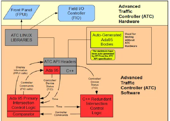
Figure 5: Overview of ATC using SCOPE Application Ada95/C++ Communication & Synchronization
The Ada95 software (primary) communicates with the C++ software (secondary) through the use of standard socket connections. The primary software acts as a server, creating a socket and accepting connections from the C++ client if it can be found. If a connection is not made after several attempts, the primary software begins execution of the control loop. The primary software still runs and controls the intersection without the redundant software executing. Under normal operating conditions a connection is established and the primary sends the secondary an initial message containing the current time. Periodically, time and request for status packets are sent to the secondary software by the primary software. In turn, the secondary software sets its clock or replies to the status request. The reply status of the secondary is compared to the primary status to determine if the software is in sync and producing
40
the same results. Up/down redundancy counters and thresholds are used to determine critical faults.
Both the primary software and the secondary software periodically register with watchdog timers set at two second intervals. If the watchdog timer expires without hearing from the primary and secondary software an indication is currently displayed on the GUI, for the testing phase, and later will be logged as a failure to the ATC. A future enhancement being considered for SCOPE is secondary taking the role of the primary if for any reason the primary stopped communication with the watchdog.
Preemption Design
One of the key elements of designing ATC compliant software is the ability to immediately respond to preemption events (train, ambulance, pedestrian, etc). For example, a preemption event would be the approach of an ambulance triggering an “all-red” intersection. Another example would be a pedestrian preemption altering minimum green times to accommodate the pedestrian clearance interval. Phase I of SCOPE incorporated NCHRP 3-66's railroad crossing preemption algorithm. Preemption is handled by checking for an event every 50 milliseconds when the primary software is in steady state. Instead of using hardware interrupts, SCOPE's main thread used the delay feature of Ada95 to release control of the processor and allow external events to be processed by subtasks. This method ensured that the software had no greater than a 50 millisecond response time to a preemption event.
For Phase II, the SCOPE primary processing uses a more deterministic method of execution. Instead of assigning a separate task to every independent traffic phase, SCOPE has a main task that contains a sequential execution loop. The loop executes at an adjustable rate (currently set to 100 ms). Polling for external events occurs at the end of each pass. As part of Phase II, SCOPE's sponsors chose additional NCHRP 3-66 actuated concepts to be incorporated into SCOPE. This six month task began after SCOPE