OPTICAL SYSTEMS I LASERS & MATERIAL PROCESSING I INDUSTRIAL METROLOGY I TRAFFIC SOLUTIONS I DEFENSE & CIVIL SYSTEMS
ProgRes
®
MAC CapturePro 2.7
User advice
Dear user,
Please read the instructions in this manual carefully before starting to operate the software ProgRes® MAC CapturePro 2.7.
Editorial deadline: April 2009
Document number: 014102-100-98-02-0904-en
JENOPTIK I Optical Systems
Business Unit Digital Imaging Goeschwitzer Str. 25 07745 Jena Germany Tel.: +49 3641 65-2143 Fax: +49 3641 65-2144 E-Mail: [email protected] www.progres-camera.com Revision state
Date Release Revision
February 2010 001 002
CE
Note:No part of this manual may be reproduced in any form (print, photoco-py, microfilm or any other process) nor may it be processed, duplicated or distributed using electronic systems without a prior written per-mission of JENOPTIK. The manual was produced with the appropriate care. No liability will be accepted in the case of damages arising from the non-observance of the information contained herein.
We reserve the right to modify this document following technical advancements.
User advice
Signs and symbols
•
EnumerationC
Advice / Important / Important adviceg
Reference (to a text passage or image)Warning symbols
Warning: Warning against the risk of damage or injury.
Caution: Warns against potential damage or malfunction of the product.
Information: Refers to important data or details.
This symbol refers to special guidelines that have to be followed when disposing the product.
Contents
Table of contents
Signs and symbols ...3
Warning symbols ...3
1 Introduction ...7
1.1 Welcome ...7
1.2 Intended operation of the ProgRes® cameras ...8
1.3 Feedback: approval, criticism, suggestions ...9
2 Safety instructions ...10
2.1 General safety information ...10
2.2 Operating, storage and transportation conditions ...11
2.3 Application fields of the ProgRes® cameras ...12
2.4 Electrical installation conditions ...12
2.5 Advice for handling and operating the camera ...13
2.6 Cleaning and maintenance ...13
2.7 Exemption from statutory liability for accidents ...14
2.8 Exemption from warranty ...14
2.9 Safety note for use in the United States of America ...14
2.10 Disposal ...15
3 Installation and software start ...16
3.1 Installing the software ProgRes® MAC CapturePro ...16
3.2 Starting the ProgRes® MAC CapturePro ...19
3.3 Mounting the ProgRes® camera to a microscope ...19
3.4 Connecting the ProgRes® camera to a computer ...19
4 Software user interface ...21
5 Menu bar ...23
5.1 The menu “ProgRes®“ ...23
5.2 The menu “File” ...24
5.3 The menu “Edit” ...25
5.4 The menu “Camera” ...25
5.5 The menu “Window” ...25
6 Image display and acquisition ...26
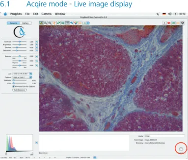
6.1 Acqire mode - Live image display ...26
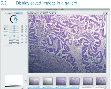
6.2 Display saved images in a gallery ...27
6.2.1 Load an image from the gallery ...28
6.2.2 Edit an image in the gallery ...28
6.3 The icon bar ...29
6.3.1 Display exposure warnings ...29
Contents
6.3.3 Setting and saving image crops ...30
6.3.4 White balance ...30
6.3.5 Black balance ...31
6.3.6 Change color mode ...31
6.3.7 Measurement layer ...31
7 Operational windows ...33
7.1 Setting preferences ...34
7.1.1 Image info ...34
7.1.2 Acquire ...35
7.1.2.1 Setting prefix and format ...35
7.1.2.2 Auto Save ...36 7.1.2.3 Auto Open ...37 7.1.2.4 Options ...38 7.1.3 User interface ...38 7.1.4 Timelapse ...39 7.1.4.1 Save images in ...40 7.1.4.2 Save images as ...40 7.1.4.3 Save Protocol ... 40 7.1.4.4 Time Control ...41 7.1.5 Measurement ...42 7.1.6 Fluorescence ...44
7.2 Timelapse: time-controlled image capturing ...45
7.3 Calibration... 47
7.3.1 Black shading calibration ...48
7.3.2 White Shading Calibration ...48
7.3.3 Scanner calibration ...49
7.3.4 Activate cooling ...53
7.4 Measurement window ...54
7.4.1 Create or edit a calibration ...54
7.4.2 Insert a new unit or edit a unit ...56
7.5 Fluorescence image capturing ...57
7.5.1 Carry out a fluorescence project ...58
7.5.2 Adjust captured fluorescence images...59
7.5.3 Load fluorescence projects ...61
8 Operating Panel ...62
8.1 Adjust brightness, contrast, gamma and saturation ...62
8.2 Adjust balance ...63
8.3 Image resolution ...64
Contents
8.4.1 Adjust exposure ...64
8.4.2 Adjust gain ...65
8.5 Histogram ...67
9 Image description area ...68
10 Image information bar ...69
11 Service and support ...70
11.1 Manufacturer service & support...70
11.2 Return address for goods in case of service incidents ...70
11.3 Camera registration and software updates ...70
11.4 Further Information ...70
12 Technical specifications of ProgRes® cameras ...71
12.1 Generals ...71
12.1.1 Type plate and order numbers ...71
12.1.2 Scope of delivery ...72
12.1.3 Certificates and approvements ...73
12.1.4 System requirements ...73
12.2 Image resolution of the ProgRes®-cameras ...74
12.3 Technical data sheets ...80
12.3.1 ProgRes® CCD research cameras ...80
12.3.2 ProgRes® CMOS cameras ...83
12.3.3 ProgRes® CCD routine cameras ...85
Introduction
1
Introduction
1.1
Welcome
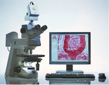
Welcome to your new Jenoptik ProgRes® digital camera system. You
have purchased a reliable state-of-the-art digital microscope camera for image analysis and documentation with the operational software ProgRes® MAC CapturePro for operating your microscope camera from
a Macintosh computer.
Fig. 1 / 1 Microscope Workstation with ProgRes® camera.
The following manual applies to the operation of the ProgRes®
microscope cameras using the ProgRes® MAC CapturePro application
software.
In case that any differences occur in operating the camera types, you will be explicitly informed about these differences.
Operating your ProgRes® camera with the new ProgRes® MAC
Introduction
take the time to read through this operating manual in order to get familiar with the camera, the software and the safety advice.
C
Important note: Please take the time to register as a ProgRes® user on our web site at www.progres-camera. com. As a registered user, you will have access to software downloads, and you will be automatically informed when a software update is available.1.2
Intended operation of the ProgRes
®cameras
ProgRes® microscope cameras are intended for the operation with a
microscope and for the operation and image analysis with the suitable software. Application software is available for the operating systems MAC OS and WINDOWS. In this manual, the software for MAC OS is described.
C
Important note: Presently, only ProgRes® microscopecameras with a Firewire interface can be operated using MAC OS and the software ProgRes® MAC CapturePro. If you would
like to work with a USB-camera, please contact your expert dealer or the technical support of the manufacturer. ProgRes® cameras are suitable for applications in science and research
as well as in production that require high quality microscopic image reproduction. Typical application fields are:
• Material science (metallography, quality control) • Life science (genetics, pathology, biology) • Forensics (securing of evidences)
ProgRes® digital cameras are designed and manufactured for the use in
clean and dry locations (according to EN60950). They are intended for digital image acquisition. Any use in human medical technology accor-ding to IEC601-1-1 is not allowed and herewith is excluded explicitly.
Introduction
1.3
Feedback: approval, criticism, suggestions
We strongly rely on your most welcome feedback for improving our products according to your needs. Please let us know what you like about the ProgRes® cameras and the ProgRes® MAC CapturePro
soft-ware, tell us what you dislike and also what you are missing.
We will try to consider your feedback in the further development of our products – and in this way we will let you benefit from such improve-ments.
Please send your feedback to: [email protected]
We wish you every success with your ProgRes® microscope camera!
Safety instructions
2
Safety instructions
The ProgRes® digital microscope camera is manufactured and tested
ac-cording to the regulations specified in EN60950 / VDE0805, and was in perfect working condition when leaving the manufacturer’s premises. In order to maintain this standard and to avoid any risk when opera-ting the system, please make sure to comply with the advice and the warnings contained in this manual.
No warranty will be assumed by the manufacturer during the warran-ty period if the equipment is operated without observing the safewarran-ty regulations. In any such case, JENOPTIK shall be exempt from statutory liability for accidents resulting from any operation.
Please read this chapter carefully and observe the regulations in order to ensure your safety, and to operate the ProgRes® camera as intended.
Please observe the warnings and notes printed in this manual and on the unit.
2.1
General safety information
Expansions and alterations
The system must be operated in accordance with the instructions. Any expansions, re-adjustments, alterations and repairs may only be carried out by persons who have been authorized by JENOPTIK. The electrical installations of the room where the system is set up must be in accordance with IEC requirements. Please refer to chapter 2.4 “Electrical installations“ for the electrical installation conditions, and observe the information contained in that chapter.
Safety instructions
Danger
In the following cases, the use of the camera can imply the danger of-personal injury or of damage to the instrument. Please do not operate the camera in the following cases:
•
The camera is visibly damaged.•
The camera has been stored under adverse conditions over a long period.•
The camera has been transported under adverse conditions. In these cases, the camera has to be switched off and protected against unintentional use. Please contact your dealer or the technical support of the manufacturer.2.2
Operating, storage and transportation conditions
Operating temperature: +5 °C ... +35 °C
Humidity: 5 % ... 80 %, non-condensing
Storage temperature: -10 °C ... +50 °C
Please store the camera in a dry and cool place.
Environmental conditions
ProgRes® digital cameras are manufactured for the use in clean and dry
environments (according to EN60950). Please do not expose your ca-mera to extreme environmental conditions. Keep it away from extreme temperatures, high humidity, fluids, chemical gases or high electroma-gnetic fields. Details can be found in the technical specifications.
Static electricity
Static electricity can damage or even destroy the delicate electronics of your camera. Before you connect the camera to a computer or a microscope, please make sure that it is free of electrostatic charge. Ground yourself by touching the metallic housing or the reverse side of your computer or microscope, which both have to be grounded via a power socket.
Safety instructions
Ventilation
Ensure the sufficient ventilation of the camera. Make sure that the louvers on the camera back are not covered. Avoid direct sun exposure and the location nearby any heat sources (radiators, stoves). Overhea-ting can cause poor image quality. To avoid the risk of fire, do not use the camera near inflammable liquids or gases.
Transportation
The camera has to be protected against mechanical impact, and there-fore may only be transported or stored in the supplied carrying case. When the camera is transported or stored, please use the supplied C-mount cover.
2.3
Application
fields of the ProgRes
®cameras
ProgRes® digital cameras are designed and manufactured for the use in
clean and dry locations (according to EN60950). They are intended for digital image acquisition. Any use in human medical technology accor-ding to IEC601-1-1 is not allowed, and herewith is excluded explicitly.
2.4
Electrical installation conditions
The electrical installations of the room where the system is to be set up must be in accordance with IEC requirements.
Voltage
supply 8 ... 33 VDC (via IEEE1394 connector) Power
con-sumption Variable according to the camera type. Please refer to the technical data sheet of your camera in chapter 12 in this manual.
To interrupt the power supply of your camera, please unplug the IEEE-1394 FireWire cable.
Only use the cables supplied by the manufacturer. No warranty will be assumed for damages or injuries arising from the non-compliance with this advice. Do not allow any cables, particularly power cords, to trail
Safety instructions
across the floor.
The electrical cables have to be protected against mechanical impact. Connect and disconnect the cables by pulling the connector.
2.5
Advice for handling and operating the camera
Your digital ProgRes® camera is an optical, fine mechanical precision
device. Please handle it with the due care. The reliability and perfor-mance as well as the longevity of the system can only be guaranteed if all safety instructions are observed.
The built-in IR filter glass has to be protected against mechanical impact such as shock or scratching as well as against dirt.
Do not remove the ferrite which is mounted to the IEEE-1394 FireWire cable on the computer side.
Avoid especially any agitation of your camera during operation, as the image quality may deteriorate in this case.
To avoid the risk of fire, do not use the camera near inflammable liquids or gases.
2.6
Cleaning and maintenance
Cleaning the camera casing
If the camera casing is slightly soiled, clean it with a soft slightly moi-stened piece of cloth. Take care that no water enters the camera casing and gets in contact with the internal parts of the camera.
Do not use any aggressive substances or solvents to clean the camera.
Cleaning the IR-filter glass
The built-in IR filter glass has to be protected against mechanical impact such as shock or scratching as well as against dirt. Avoid fingerprints on the glass, and do not touch the aperture of the C-mount connection.
Safety instructions
Commercial detergents must not be used for cleaning the filter glass. Please contact your dealer if cleaning of the filter glass should become necessary.
Use a brush to remove dust. For the transportation and the storage of your camera, please use the supplied C-mount cover.
2.7 Exemption from statutory liability for accidents
JENOPTIK shall be exempt from statutory liability for accidents in the case of non-observance of the safety regulations by any operating person.
2.8
Exemption from warranty
JENOPTIK shall be exempt from warranty during the warranty period if the equipment is operated without observing the safety regulations. In any such case, JENOPTIK shall be exempt from statutory liability for accidents resulting from any operation.
The camera was in perfect working condition when leaving the manufacturer’s premises. In order to retain this standard and to avoid any risk when operating the system, the user must comply with the advice and warnings contained in this manual.
2.9
Safety note for use in the United States of America
This device complies with Part 15 of the FCC Rules. Operation is subject to the following two conditions:
(1) this device may not cause harmful interference, and
(2) this device must accept any interference received, including inter-ference that may cause undesired operation.
Safety instructions
2.10
Disposal
Special environmental protection guidelines apply when disposing the ProgRes® microscope cameras. Do not dispose your ProgRes®
micro-scope camera with the usual domestic refuse. Contact your dealer in case of any questions.
Installation and software start
3
Installation and software start
The ProgRes® microscope cameras are operated using the ProgRes®
MAC CapturePro software. For a safe installation, observe the following advice.
C
Important note: Before connecting the ProgRes® camera toyour Macintosh computer, it is necessary to install the appli-cation software, which also includes drivers for the ProgRes®
cameras.
3.1
Installing the software ProgRes
®MAC CapturePro
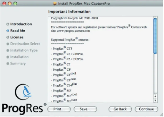
Double-click on the installer icon and follow the instructions displayed on the screen. The installation routine is started.
Fig. 3 / 1: Installation - “Readme“-screen
The “readme“-screen provides information about the available ProgRes®-cameras, the system requirements and the contact data.
Installation and software start
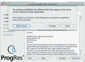
Fig. 3 / 2: End user license agreement
In the next screen, the end user license is displayed. The license must be accepted. When “Continue“ is clicked, a dialogue window is displayed where the end user license can be accepted.
Fig. 3 / 3: Select destination
In this screen, the installation location can be selected. If you click “Change Install Location“, a window opens where the installation loca-tion can be selected. If no installaloca-tion localoca-tion is selected, the program is installed automatically in the directory “Applications“. By clicking
Installation and software start
“Continue“, the installation will be continued.
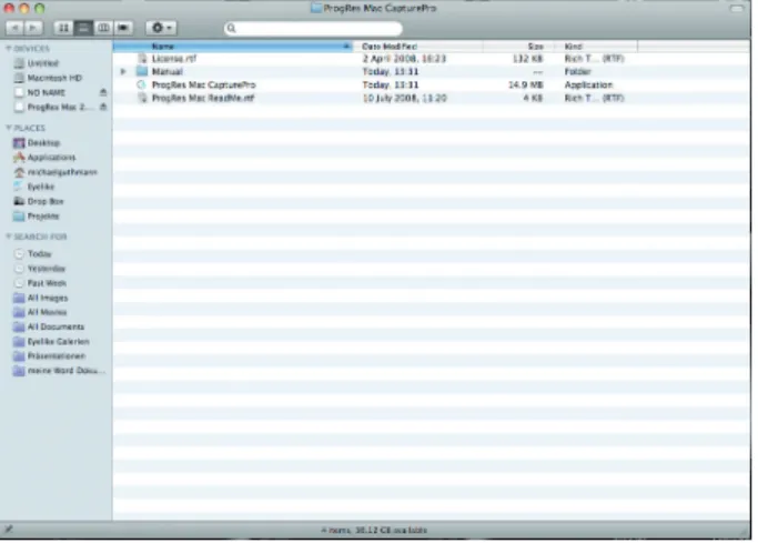
Fig. 3 / 4: Display folders
The application software is installed. The folder Progres Mac Capture-Pro is created, and the files contained in this folder are displayed in the screen.
After installing the application software, the ProgRes® camera can be
connected to your computer by the supplied FireWire cable.
C
Note: It is recommended to deactivate the “Power Save” settings of your computer while working with the ProgRes®Installation and software start
3.2
Starting the ProgRes
®MAC CapturePro
Connect your ProgRes® camera to your computer with the supplied
FireWire cable. You can operate ProgRes® cameras that are equipped by
a Firewire interface using the ProgRes® MAC CapturePro software.
Start ProgRes® MAC CapturePro by double-clicking the
ProgRes® software icon.
The software will recognize the connected ProgRes® camera during
the start, and the specific camera data will be loaded (e.g. camera type, serial number, live image and image capture modes).
3.3
Mounting the ProgRes
®camera to a microscope
The camera is equipped with a C-Mount interface. The camera is mounted to the microscope via this interface. For mounting, a C-mount adapter is used. The adapter type depends on the microscope you are using and is not included in the delivery.
3.4
Connecting the ProgRes
®camera to a computer
Depending on the camera type, the ProgRes® cameras can be operated
via Firewire (IEEE-1394) or USB. When the camera is mounted on the microscope, set up the connection with the respective USB or firewire cable.
C
When operating the ProgRes® cameras using MAC OS andProgRes® MAC CapturePro, the camera can only be operated via
Installation and software start
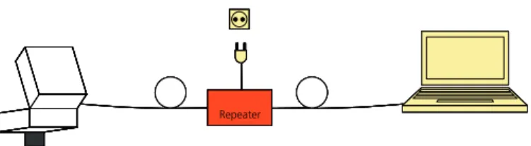
Repeater Repeater Repeater Repeater RepeaterFig. 3 / 5: Connecting the ProgRes® camera to a laptop computer via Firewire
USB
Power supply and data communication are realised via USB for PC and Laptop computers. No additional power supply is necessary. Connect the camera to your laptop or PC using the USB-cable.
Firewire
When operating the ProgRes® cameras from a desktop computer,
power is supplied using the Firewire cable. When a laptop computer is used, power has to be supplied additionally using the suitable repeater.
C
Suitable PCIMCIA-cards and Firewire boards are listed in chapter 12 “Technical specifications“.Software user interface
4
Software user interface
Fig. 4 / 1: Software user interface
The software user interface is divided into the following areas: Menu bar (orange frame)
In the menu bar, the features and functions for the general operation of the ProgRes® MAC CapturePro software are found, g chapter 5
“Menu bar“.
Buttons “Acquire“ and “Gallery“ (red frame)
The main section buttons „Acquire“ and „Gallery“ enable image acqui-sition and the display of saved images in a gallery, g chapter 6 “Image display and acquisition“.
Image window (yellow frame)
In the image window, the live image or the images loaded from the gallery are displayed.
Software user interface
Icon bar (green frame)
The buttons in the icon bar enable the access to several image settings, g chapter 6.3 “The icon bar“.
Buttons for operational windows (brown frame)
By clicking these buttons, operational windows are opened on the right side oft the software interface enabling the setting of preferences, the time-set image capturing, shading calibration, measurement calibration and fluorescence image capturing.
Operating panel (blue frame)
The operating panel enables functions for the setting of the image resolution of the live image and the captured image, and for the adjust-ment of exposure and gain. Furthermore, the setting of image contrast, brightness and saturation and the adjustment of the color channels can be selected. The color channels are visualized in a histogram in the lower part of the panel. The operation panel is described in more detail in chapter 8 “Operating Panel“.
Image description area (pink frame)
In this area, comments to the captured image and the image prefix can be entered. These data are stored when the image is captured by pressing the button “Acquire” . Please refer to chapter 9 “Image description area“ for more details.
Image information bar (black frame)
This bar indicates the current image values, like cursor position, frame rates or the camera type connected. The image information bar is described in chapter 10 “Image information bar“.
The functions of the software user interface will be described in more detail in the following chapters.
Menu bar
5
Menu bar
Fig. 5 / 1: Menu bar
The menu bar contains general features and functions.
5.1
The menu “ProgRes
®“
The items of the menu “Progres®“ are
described in the following section.
Fig. 5 / 2: Menu “ProgRes®“
About ProgRes® MAC CapturePro
Here, information about the software versions, camera drivers etc. are dis-played. Click onto the window to hide the window.
Menu bar
Preferences…
With a click on this menu item, the dialogue “Preferences” opens. This dialogue is also available with a click on the button “Preferences” and will be explained in chapter 7.1 Setting preferences.
Reset to Factory Settings
Resets the application settings and the camera settings to the settings preset in the factory.
Load Settings
Loads the camera settings and the settings of the software application that have been previously saved.
Save Settings
Saves the settings which are currently used in the software appli-cation. The settings can be loaded by selecting “Load settings”.
Hide ProgRes®
This option places the ProgRes® screen in the background of
your working operation.
Hide Others
Places screens of other operations in the background.
Show All
Shows all applications that are currently open.
Quit ProgRes®
Closes the application.
5.2
The menu “File”
Menu bar
5.3
The menu “Edit”
Fig. 5 / 4 Menu “Edit“
The menu “Edit“ offers the standard MAC options for editing.
5.4
The menu “Camera”
Fig. 5 / 5: Camera menu
Acquire
Displays the live image screen. From here, images can be ac-quired (g chapter 6.1 “ `Acquire´-mode”).
Gallery
Displays the captured images in a gallery. The images can be displayed and edited (g chapter 6.2 “Display saved images in a gallery”) for further information.
5.5
The menu “Window”
This menu contains options concerning the size and the display of the general application window as preset in the MAC operating system.
Image display and acquisition
6
Image display and acquisition
Fig. 6 / 1: Main section buttonsThe image acquisition and the gallery display are carried out using the buttons “Acquire“ and “Gallery“.
6.1
Acqire mode - Live image display
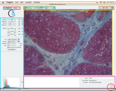
Fig.6 / 2: Acquire screen
After connecting your camera, the live image from the microscope is displayed in the software user interface. The image is continuously refreshed and will not be stored on your hard disk drive unless captured with a click on the button ”Acquire”. You can either use the button ”Acquire“ above of the operating panel, or in the lower right corner (marked with a red circle).
If the image exceeds the size of the image window, you can use the scroll bars below and at the right side for moving the image.
Image display and acquisition
image window.
Settings for the camera and the image adjustments can be selected. The operation panel left of the main image display window offers func-tions for the definition of the following settings:
• Image resolution for live mode, capture mode, exposure and gain • Contrast, brightness, gamma and saturation
• Color balance adjustment
A detailed description of the operating panel and its functions, and the details of the resolution of the different camera types can be found in chapter 8 “Operating panel“.
6.2
Display saved images in a gallery
Fig. 6 / 3: Image screen with gallery
By pressing the button “Gallery“, captured images that have been saved in a folder are displayed. The folder for the captured images is selected in the dialogue “Preferences” (g chapter 7.1 “Setting preferences“). In the gallery mode, the images of the folder last opened are displayed.
Image display and acquisition
If the software is reopened, the last used gallery will be displayed. If another image is captured, it will be added to this gallery automatically if no other folder for image storage has been selected.
6.2.1 Load an image from the gallery
To display an image from the gallery in the main window, please click on the respective image in the gallery.
If you wish to open another gallery, please click the button in the icon bar. This button is only available in the gallery mode. The finder opens where the folder can be selected.
C
Please note: An image stored in a folder can only be loadedin the main window by displaying the images of the folder in the gallery and selecting the respective image from there.
6.2.2 Edit an image in the gallery
An image in a gallery can be edited by CTRL+click on the respective image. A dialogue opens that offers the following functions for editing the image.
Rename
Renames an image. The new image name can be entered into the text box under the image after selecting this function. Click [Enter] to apply the name.
Duplicate
Duplicates the image. The image will be automatically added to the images in the gallery.
Delete
Deletes the selected image.
Show in finder
Shows the storage place of the selected image.
Show image info
Image display and acquisition
can be set under “Image info” in the dialogue “Preferences”
(g chapter 7.1 “`Setting Preferences…‘” for further information). To leave the gallery mode, click “Acquire”.
6.3
The icon bar
With the buttons of the icon bar, settings for the image display can be defined and a measurement layer can be applied.
6.3.1 Display exposure warnings
With a click on the button “Exposure warning”, the areas in the image which are under- or overexposed will be displayed in color. The colors have to be selected and the display of these areas has to be activated in the file card “User interface” under “Preferences” (g chapter 7.1.3 “User interface“).
6.3.2 Zoom and rotation
With the “Zoom”-buttons, the image size can be enlarged or reduced. If the image is larger than the display window, scrollbars appear on the right and the lower side of the image and can be used to navigate within the image. The function “Zoom-to-fit“ enables the adaptation of the microscopic image to the image window in the software user interface. The function is opened by right-clicking onto the “Zoom“-buttons.
In the upper area, the zoom-factor (percentage) can be selected.
The “Zoom-to-fit“-function adapts the image automatical-ly to the software user interface.
Image display and acquisition
The “Hand“-tool can be used to navigate within an enlar-ged image. Click left into the image and pull the mouse into the desired direction. The image region in the display window will be shifted accordingly.
Using the “Rotate”-button, the image can be rotated in steps of 90°.
6.3.3 Setting and saving image crops
Using the button “Crop”, an image region can be defined that can be saved. A rectangle appears for the selection of this image area. The selected crop region can be saved with a click on the button “Acquire”. The crop images can be displayed and loaded in a gallery. Using crop images, saving time and storage capacity can be reduced. The dimensions of this area can be changed with a click on the corners of the rectangle and by moving the mouse simultaneously. The position of the rectangle is changed by a click into the rectangle and by moving the mouse. When the button “Crop” is clicked again, the rectangle disappears. With a repeated click on the “Crop”-button, the rectangle appears again in the dimensions which have been recently defined.
6.3.4 White balance
In the software window, slight deviations to the micro-scopic image in white / neutral colors may occur due to camera internal settings. With a white balance adjustment, these deviations can be compensated.
Image display and acquisition
Activate the pipette tool and click onto a position that depicts a neutral area in your specimen. The image will be changed accordingly. Please note that the areas in the image will be adjusted to a neutral color, not to pure white. The reset button resets the white balance to def-ault.
C
Note: Before using another function of the icon bar, please click the button “White Balance” again to deactivate the function.6.3.5 Black balance
The function “White Balance“ changes to “Black Balance” in the fluorescence mode or in the black and white mode. With a black balance, areas in the image can be defined that are to be displayed in black (RGB-values=0).
Use the black pipette to carry out a black balance at any location in the image. If an unsuitable location in the image has been selected, the black balance can be reset using the arrow.
6.3.6 Change color mode
With this button, the image color can be changed to black and white or to RGB-color. Depending on the color mode which is currently active, the button will change.
6.3.7 Measurement layer
A measurement layer comprises one or more shapes which can be inserted into the image.
With a click on this button, the measurement layer can be shown or hidden.
To select a measurement layer option, click on the arrow buttons next. A drop-down menu opens where the mea-surement shape can be selected.
Image display and acquisition
A line or a horizontal / vertical scale can be inserted into the image. The size of these shapes can be changed with a click on the dots at the corners of the shapes. To change the size of the measurement shapes retroactively, click on the shape and pull the corner dots with the mouse. When the button “Acquire” is clicked, the layer will be saved with the image. The layer of a saved image cannot be edited retroactively. When the layer is hidden, it will not be saved with the image.
Operational windows
7
Operational windows
The buttons “Preferences“, “Timelapse“, “Calibration“, “Measure“ and “Fluorescence“ enable the access to further operations of the software. By clicking the buttons, a window opens for defining settings or perfor-ming image capture functions.
The buttons are located in the upper right area above of the image display and enable the following functions:
Preferences
Set preferences for image capturing and saving. The preferences can also be set in the menu “ProgRes“.
Timelapse
Set time-controlled image capture and saving. Calibration
Perform shading and scanner calibration. Measure
Select settings for measurement in the image. Fluorescence
Perform fluorescence image capturing.
C
Note: The functions “Timelapse“, “Calibration“ and “Measure“ are not available in the Gallery-mode.Operational windows - Setting preferences
7.1
Setting preferences
In the dialogue “Preferences”, settings for the image acquisition and measurement as well as display settings for the user interface can be selected. The screen “Preferences…” is divided into 6 register cards. Clicking “Preferences…” automatically opens the last register card left with “OK”. With the first software start, the register card “Image Info” is opened.
Fig. 7 / 1: Menu bar in the dialogue “Preferences”
It is recommended to adjust your camera and microscope according to your requirements before starting your working session. All settings will influence the operation of the camera, and will be automatically saved when closing the software. After restart, these adjustments will be available again.
The following buttons are available in each index card:
• With “Reset”, all settings in the image are reset to factory settings. • With “OK”, the changes inserted in the window are applied. • With “Cancel”, the application is reset to the action last performed.
7.1.1 Image info
Operational windows - Setting preferences
Information about the author, the user and the company, and an image description can be entered into the input boxes that will be saved as a meta file with the captured image. By marking the respective checkbox the image information to be saved with the captured image can be selected. The detailed comment will be displayed in the description box under the image in the “Acquire”-mode.
C
Note: The saving of the image information reduces the cap-ture performance in time lapse capcap-ture.C
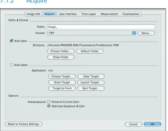
Important note: The image information can only be stored with the file formats TIFF, Photoshop, JPEG and JPEG 2000.7.1.2 Acquire
Fig. 7 / 3: Dialogue “Preferences – Acquire”
In this register card, the storage location of the captured images, the target application for working with ProgRes TWAIN and the image options can be defined.
7.1.2.1 Setting prefix and format
Enter an image name prefix for image saving. When “Auto Save“ is enabled, images will be saved automatically using the name prefix combined with an ascending number.
Operational windows - Setting preferences
Click onto the arrow buttons to open the dialogue for selecting the file formats. The file formats and bit depths that can be selected are shown in Fig. 7 / 4 „Storage formats“.
Fig. 7 / 4: Storage formats
Clicking the button “Setup“, a dialo-gue is opened where the settings for the respective file format can be de-fined. This dialogue varies according to the selected format.
Fig. 7 / 5 shows the options for a JPG-image.
Fig. 7 / 5: Adjustments
7.1.2.2 Auto Save
If “Auto Save“ is enabled by marking the respective checkbox, the cap-tured images will automatically be saved in a folder without a request for file name and location. The folder can be specified by clicking the button “Choose folder”. The name of the folder will be displayed below the checkbox over the buttons.
• Choose Folder:
Chooses the folder where the captured images will be stored automatically.
• Default Folder:
Creates a folder on your desktop with the current date as folder name.
Operational windows - Setting preferences
• Show Folder:
Opens the folder you have selected for Auto Save.
C
Note: To open a captured image, the folder where the image is stored has to be displayed as a gallery. The image can be shown in the display window by selecting it from the gallery (g chapter 6.2 “Display saved images in a Gallery´”).7.1.2.3 Auto Open
If “Auto Open“ is enabled, the captured images will be stored tem-porarily on the hard drive of your computer, and will be automatically opened with the selected target application program (for example Adobe Photoshop).
Choose Target
When working with the TWAIN application, first choose the target application for opening your captured images. The finder will open where you can select your target application. By a click on “Open”, the target application will be assigned to the ProgRes® MAC CapturePro
application. It will be started with a click on “Launch target”.
Clear Target
Resets the assigned target application for AutoOpen.
Show Target
Shows the selected target application in the finder.
Launch Target
Starts the target application in the background of ProgRes® MAC
CapturePro.
Target to Front
Brings the target application window to the front. When the “Command”-key is pressed while clicking the “Capture”-button, the image in the target application will appear in the front and can be edited.
Quit Target
Operational windows - Setting preferences
7.1.2.4 Options
Here the AutoExposure settings can be selected. Mark the respective options to preserve the gain currently set in the image or select the automatic optimization of exposure and gain. With a click on “Reset”, any settings in the index card “Acquire” are reset to the factory settings.
7.1.3 User interface
Fig. 7 / 6: Dialogue “User interface” with color selection box
In the dialogue “User interface“, the display of over- or underexposed areas in the image can be selected.
Mark the checkbox to activate the display of the exposure warning. Click the arrow buttons to adjust the theshold value for the over- or un-derexposed areas. It is recommended to set a value of 250 grey values for overexposure and of 5 grey values for underexposure.
To select the color for the under- and overexposed areas, click on the colored boxes. A dialogue opens where the color for the display of exposure warnings can be selected. The colored areas in the image will indicate under- or over-exposed areas.
Operational windows - Setting preferences
By a click on the button in the icon bar, the under- or overexposed areas in the image selected in the register card are shown or hidden. With “Reset to Factory Settings”, the settings in the index card “User interface” are reset to the factory settings.
With “OK”, the changes inserted in the window will be applied. Click “Cancel” to reset the changes to the factory settings.
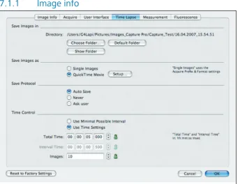
7.1.4 Timelapse
Fig. 7 / 7: Index card “Timelapse“
In the index card “Timelapse”, the settings for time-controlled image capturing can be defined. The time-controlled image capturing is started with a click on the button, g chapter 7.2 “Timelapse: Time-controlled image capturing“ for further information.
Operational windows - Setting preferences
7.1.4.1 Save images in
Choose the storage place for the time-controlled capturing of images.
• Choose Folder
Choose the folder for saving the images in the finder. • Default folder
A folder will be created on your desktop with the current date as a folder name. The images will be stored in this folder.
• Show folder
The folder where the images will be stored is displayed on the screen.
7.1.4.2 Save images as
Chooses the file format for the images to be stored. The images can be stored as a sequence of single images or as a QuickTime Movie.
Fig. 7 / 8: Select movie format Both formats will be stored in the folder
specified under “Save images in”. When the images are captured as a se-quence of single images, the file format as selected on the index card “Acquire” (g chapter 6.1 “Acquire-mode“) will be used. For a QuickTime Movie, the format can be specified with a click on the button “Setup”. A menu opens where the format for the movie can be selected.
7.1.4.3 Save Protocol
The settings for saving the protocol of the time-controlled image cap-turing can be defined. The protocol is saved as a text file together with the captured images in the selected folder.
Auto Save
Operational windows - Setting preferences
Never
No protocol will be saved with the images.
Ask user
The user will be asked whether the protocol is to be saved with the images.
7.1.4.4 Time Control
Fig. 7 / 9: Preferences – Time control settings
Here the settings for the time-controlled image capturing are defined. The image capturing can be performed either by using the minimal possible interval or by using the time settings which are inserted by the user. Depending on the selected option, the input boxes “Total time” and “Interval” will be active or will change automatically.
Use Minimal Possible Interval
When this option is selected, the images will be captured as fast as possible. The image number has to be inserted into the box “Images”. The input boxes “Total Time“ or “Interval Time“ will be deactivated.
Use Time Settings
Here the total recording time (Total Time), the time interval between two captured images (Interval Time) and the total number of images can be inserted. By clicking on the padlock symbol, one option can be set as fixed. The data of the other options will be adjusted automatical-ly if one of them is changed.
Example: A fixed time interval between two captured images is set, which cannot be altered. When the number of images is changed, the total recording time is adapted automatically.
Operational windows - Setting preferences
7.1.5 Measurement
Fig. 7 / 10: Index card “Measurement“
In the index card “Measurement”, the settings for the display of the measurement overlay in the image can be defined.
Lines
The color and the width of the lines can be set. A line width of one pixel is set by default. The line width can be altered using the arrow buttons. The line color can be selected with a click on the color box. A dialogue opens where the color can be selected. When the button “Use Font Color” is pressed, the color selected for the font will be applied to the lines.
Font
The font color can be defined with a click on the color box and by selecting the color in the subsequently opened window. The font can be set by a click on the button “Set Font” and by defining the font parameters in the subsequently opened window.
Operational windows - Setting preferences
Fig. 7 / 12: Select settings for the font of the overlay
Fig. 7 / 11: Set line and font color
Scale
Sets the display settings of the scale. Using the arrow buttons, the number of subdivisions (max. 20) can be altered. 5 subdivisions are set by default. By marking the checkbox “Show Frame”, the scale will be displayed with a frame.
A scale for referencing distances in the image can be set by clicking in the icon bar. Clicking the arrow buttons of the function enables the subsequent selection of a horizontal or vertical scale.
Label
Marking the checkbox “Show Length“, the length of the scale and the measurement elements in the image are displayed.
Images
When the checkbox is marked, grayscale images are saved as color images.
Operational windows - Setting preferences
7.1.6 Fluorescence
Fig. 7 / 13: Index card “Fluorescence”
In this index card, the filters used for capturing multi-channel fluores-cence images can be activated and edited. Please see chapter 7.5 “Fluorescence image capturing“ for further information.
Filters
To add a filter, click the button and insert the dye name and the emission in nm in the dialogue which opens. Click “OK” to add the filter to the list in the table window. To edit a filter, double-click on the filter or mark the filter and click the button “Edit”, and change the dye name and the emission (in nm) in the subsequently appearing window. Using the checkbox “Active”, the filter can be activated and deacti-vated. The activation of a filter can also be carried out in the column “Active” in the display window of the filters.
To delete a filter, mark the filter in the display window and click the button . The filter will be deleted.
Options
Here a prefix for merged images can be inserted. When an image is captured using different filters, the different images can be
super-Operational windows - Timelapse
imposed and will form one image, in which the respective areas are displayed in different colors (g chapter 7.5 “Fluorescence image capturing“).
7.2 Timelapse: time-controlled image capturing
With a click on the button “Timelapse” , a window opens enabling the time-controlled image capturing. The settings are selected in the index card “Preferences – Timelapse”(g chapter 7.1.4 “Timelapse“).
Fig. 7 / 14: Image display with drawer “Timelapse“
When the button “Start Time Lapse now” is clicked, the time-controlled image capture is started immediately.
When “Start Time Lapse delayed” is clicked, a window opens where the delay of the start of the image capturing can be inserted.
With a click on “Start”, the “Count down” to the start of the image re-cording is started and displayed in a window. With a click on “Cancel”, the process can be cancelled.
Operational windows - Timelapse
Fig. 7 / 15: Insert delay of image capture Fig. 7 / 16: Display of remaining time to start
The progress of the image recording can be viewed in a display window in the image, and in the protocol in the window “Timelapse”. In the window, the recorded images with the capture time are listed. When the time lapse image capture is complete, “Timelapse stopped” appears at the end of the list.
If the saving of the protocol is activated in the index card “Preferences – Timelapse”, the protocol will be saved as a text file in the same folder which has been defined for the captured images.
C
Note: When the function „As fast as possible“ is selected, the images are saved during the transfer from the camera to the mo-nitor. This saving procedure achieves high frame rates, however the saving intervals are not constant.C
When the time-controlled image saving is selected, constant frame rates are achieved. The Live-mode is stopped, the image resolution is adapted and the image is saved in the directory. Be-cause of these intermediate steps, it might occur that the frame rates are slower than selected, depending on the performance of your system.Operational windows - Calibration
7.3
Calibration
With a click on the button “Calibration” , a window opens enabling the following calibration functions:
• Black shading calibration • White shading calibration • Scanner calibration
The following functions are available in the calibration window:
Information
Displays the camera type, the serial number and the firmware version number.
Black Shading Calibration
With a click on this button, a black shading calibration is started.
With a click on “Reset Black Shading”, the calibration is reset. Mark the checkbox “Apply…” to apply the calibration to the live image.
White Shading Calibration
Perform a white shading calibration. With a click on “Reset white shading”, the white shading calibration is can-celled. Mark the checkbox “Apply…” to apply the calibration to the image.
Scanner calibration
The scanner can be calibrated with a click on the respective button. Mark the checkbox to show the calibration rectangle in the image display.
Fig. 7 / 17: Window “Calibration“ If a calibration has already been set, “Available” and the date of creati-on are displayed next to the “Shading”-buttcreati-on.
Operational windows - Calibration
Cooling
Mark the checkbox to activate the cooling of the camera.
With a click on the button “ Help“ a window opens displaying detailed explanations of the respective calibration procedure.
7.3.1 Black shading calibration
With a black shading calibration, the sensor noise at exposure times > 1 sec. second can be reduced by subtracting a black reference image from the captured image.
1. Ensure that no light is falling onto the CCD sensor. It may be necessary to remove the camera from the microscope and to put the CCD protection cap on, or to place the camera onto an even ground.
2. With a click on “Black Shading“, the black shading algorithm is started. After the black reference has been carried out successfully, the software will display the date.
3. Mark the checkbox “Apply black shading if available“ if you would like to apply the black shading correction to the live images. 4. The background correction will be applied automatically to any
newly captured images until it is switched off by removing the checkmark from the “Apply“- checkbox.
5. If a new black shading correction is created, the software will over-write the existing file automatically.
C
Note: The background correction will not be applied toimages in binning mode.
7.3.2 White Shading Calibration
With a white shading calibration, irregularities in the image area caused by boundary light falloff in the optical system (vignetting) or by non-homogeneous lighting can be compensated.
Operational windows - Calibration
C
Note: Before a white shading calibration can be carried out, a black shading calibration has to be available!1. Remove the object slide from the light beam.
2. Ensure that the displayed image is not overexposed at any loca-tion. The exposure in the live image can be checked by a click on the slider “Exposure“.
3. Click “White Shading“ to start the white shading algorithm. After the successful creation of a white reference image, the software will display the date of the creation of the white shading. 4. Mark the checkbox “Apply white shading if available“ if you
would like to apply the white shading correction to the captured images.
5. The white shading correction will be applied automatically to any newly captured images (only full resolution) until it is switched off by removing the checkmark from the “Apply“- checkbox. 6. If a new white shading correction is created, the software will
overwrite the existing file automatically.
C
Note: A shading correction is not applied to images in bin-ning mode.7.3.3 Scanner calibration
The calibration of the piezo-driven scanner is a requirement for micro- scanning with ProgRes® C14plus , ProgRes® MFscan and ProgRes® CFscan
cameras. With the scanner calibration, the piezo-electric elements that move the sensor during the micro scanning process are adjusted and the image quality is optimized. The calibration has been preset by the manufacturer, however, a re-calibration should be carried out occasio-nally to achieve an optimum image quality.
How does scanning work?
During image capturing in the micro scanning mode (4x-shot, 9x-shot, 16x-9x-shot, 36x-shot), the sensor is moved between the individual images by fractions of a micrometer. In 4x-shot micro scanning, the sensor is displaced by exactly one pixel width, in 16x- and 36x-shot, the CCD sensor is moved by only one half or one third of a pixel width.
Operational windows - Calibration
From these individual images captured by the sensor movement, one high-resolution final image is calculated by the software. An extremely high precision of the displacement is therefore a prerequisite for micro scanning.
During calibration, the camera first captures a high-resolution image of the calibration pattern in the micro scanning mode. Calibration patterns are included in your delivery. Within a section of this image, the extent of the displacement of the individual images is determined by the pattern structure. Using these data, the voltage values for the piezo ac-tuators are calculated and corrected if necessary. If the data exceed or fall below specific limit values, a new high-resolution image is captured in a further iteration stage, and the calculation is carried out again with the consideration of the values of the previous stage. This process will be repeated until the scanner is successfully calibrated.
Why is calibration necessary?
The scanner displacement is controlled by a mechanical system using piezo actuators, known as “scanners“. These actuators consist of piezo-electric crystals, which deform slightly when subjected to piezo-electric cur-rent. This slight deformation is sufficient to achieve the microscopically small displacement necessary for micro scanning. The extent of this deformation at a particular voltage is individual for each element, and can be affected by external factors such as environment temperature and humidity. Since the displacement has to be carried out precisely and reproducibly, the scanners have to be calibrated occasionally.
When should a scanner be calibrated?
The scanner is calibrated by the manufacturer and can be used im-mediately. This preset calibration is permanently saved in the camera EPROM, and is as a basic principle recommended for re-calibration. A re-calibration may be necessary if:
• Environmental conditions (e.g. temperature or humidity) have changed considerably since the last calibration,
• The camera has not been in use for a long time,
Operational windows - Calibration
If the camera is used under normal conditions, and if the environmental conditions have not changed, it is usually sufficient to check the calibra-tion once a month.
C
Please note: The deterioration of the image quality due to incorrect scanner calibration can be recognized at the horizontal or vertical smooth edges in the image. Transitions between black and white at a high image resolution (> 200 %) are especially suitable to check the scanner calibration: if these edges appear jagged, the scanner calibration may be incorrect.How to carry out a calibration?
To carry out a successful calibration of the camera, a pattern with sharp light and dark contrasts within a measurement section is necessary (calibration patterns are included in delivery with the ProgRes® C14plus,
ProgRes® CFscan and ProgRes® MFscan). For a calibration using a
micro-scope, an object carrier with two different gratings is included in your delivery. For the calibration of a C-mount lens, a special calibration pattern is included in the appendix of this manual.
Setting up the calibration pattern
Operational windows - Calibration
The following criteria have to be considered:
Position:
The calibration pattern has to be set up parallel to the image capture plane, i.e. perpendicular to the optical axis. This is always the case when a microscope is used. The orientation of the pattern is not important for the calibration, i.e. the chequerboard pattern does not have to be parallel to the window edges. Check the adjustment of the calibration pattern in the live image.
Pattern:
Within the image frame, several black and white squares have to be visible to check the transitions. The image frame will be visible if “Show Calibration Rectangle” has been activated in the window “Calibrati-on“. If necessary, the magnification, the focal depth of the lens or the distance of the pattern can be changed.
Exposure:
The pattern should be amply exposed, however, overexposure has to be avoided. Optimum exposure can be achieved by a click on “AutoEx-posure“ in the operating panel.
Sharpness:
For a successful scanner calibration, the calibration pattern must be slightly out of focus.
Operational windows - Calibration
Start calibration
Click on the respective button to start the calibration. When the scanner calibration has been suc-cessful, the software displays the date of its creation. The software automatically uses the calibra-tion files. If you create a new scanner calibration, the software will overwrite the existing file automatically.
Fig. 7 / 19: Scanner calibration field
If you click the “Factory Calibration”-button, all calibration files are deleted and set to factory calibration values.
C
Important note: It is important to ensure that camera andpattern are well secured, and are not subject to any vibration.
7.3.4 Activate cooling
You can mark the checkbox to activate the cooling (peltier element and fan) for the cooled cameras ProgRes® C14plus, ProgRes® CFscan, ProgRes®
CFcool , ProgRes® MFcool and ProgRes® MFscan. When the software is
first started, the cooling is deactivated to reduce the camera power consumption.
Operational windows - Measurement
7.4
Measurement window
Clicking the button , a measurement window opens for carrying out measurement calibrations. With these measurement calibrations, distances and units in the image can be referenced. In the measure-ment calibration window, distances can be set and edited.
In the area “Calibrations“, the available calibrations are listed. “Pixels” is the standard calibration preset in the facto-ry. When this calibration is selected, the lengths of the shapes in the image are shown in pixels.
In the area “Units”, the units of the shapes displayed in the window can be selected. When a new unit is selected, it will be immediately updated in the image.
Fig. 7 / 20: Window “Measurement calibration“
With a click on the buttons , an existing calibration or unit can be added or deleted . With a click on the button “Edit”, an existing calibration or unit can be edited.
In the area “Scale”, the length of the previously set scale is displayed using the currently selected unit.
C
Note: The change of the units is only possible when a user-defined calibration has been set.7.4.1 Create or edit a calibration
The calibration of the measurement units is carried out with a line for referencing distances in the image. The calibration “Pixels” is set by default. Unless a user-defined calibration is created, all distances in the image are displayed in pixels.
Operational windows - Measurement
Place the calibration slide under the microscopic lens. Click on the button to add a new calibration. In the image window, a line will appear. Using the mouse, the length and position of this line can be set that serves as a reference for the new calibration.
To edit an existing calibration, mark the calibration and click the button “Edit”. The window “New Calibration” opens and displays a line.
Fig. 7 / 21: Set a new calibration
The line has to be configured adequately for the calibration. The size of the calibration line can be changed by clicking on the blue dots and by pulling the mouse. The place of the line in the image can be changed by a click on the line and by pulling the mouse.
In the lower part of the window, the distance and the unit can be inserted corresponding to the line, and the name of the calibration can be inserted.
Operational windows - Measurement
If a calibration has been edited, the existing data will be overwritten. Click “Cancel” to reset the changes made in the window.
The name of the calibration will appear in the area “Calibrations” in the window. The selected calibration will now be used for referencing the length of the measurement shapes in the image. The desired calibra-tion can be selected by a click onto the name of the calibracalibra-tion in the respective area of the measurement window.
7.4.2 Insert a new unit or edit a unit
In the window “Units”, the available units are displayed. When a new unit is selected, the reference of the distances for the shapes in the image is updated immediately.
The following units are set by default: µm, mm, cm, m, inch and mil. If further units are desired, for example country-specific measurement units, they can be added with a click on . A window opens where the name of the unit and the length of the unit can be inserted in mm. Click “OK” to apply the settings.
Fig. 7 / 22: Insert new unit
With a click on , a selected unit can be removed. When the unit is selected and “Edit” is clicked, the unit can be edited.
C
Note: Only the units that have been individually defined by the user can be edited or removed. The units which have been set by default cannot be changed by the user. When a scale is inserted into the image, the length of the scale will be shown in the box in the area “Scale” using the selected unit. If several scales have been inserted into the image, a particular scale can be selected.Operational windows - Fluorescence
7.5
Fluorescence image capturing
With a click on the button “Fluorescence” , a window opens offering functions for fluorescence measurement.
With the button “New Session“, a new fluore-scence session is started. With the button “Last Session”, the fluorescence project which was last created is opened.
In the field “Acquire”, functions for fluorescence image acquisition can be selected. When the checkbox “Apply Filter Color” is marked, the fluorescence image is displayed in the respective filter color that has been preset in the window preferences, otherwise it is displayed in black-and-white-mode.
The field “Gallery” becomes active after the com-pletion of the fluorescence project, and enables the adjustment of the color display and the inten-sity as well as the merging of images.
Fig. 7 / 23: Fluorescence mode
In the area “Pixelshift”, the superimposed individual images can be ad-justed. Displacement due incorrect alignment of the fluorescence filters can be compensated. By a click on the button “Save merged image”, the merged image can be saved and will be displayed in the gallery.
Operational windows - Fluorescence
7.5.1 Carry out a fluorescence project
Set fluorescence filters
Before starting the fluorescence project, insert the names of the filters in the index card “Fluorescence” under “Preferences” (g chapter 7.5 “Fluorescence image capturing“). In the window “Fluorescence“, mark the filters you will use in the checkbox “Active”. Adjust the fluorescence slide preparation under the microscope and set the correct image focus.
Start session
Click the button “Start session”. A dialogue appears requesting the activation of the first fluorescence filter on your microscope. Unless the checkbox “Apply Filter Color” is marked, the fluorescence image will be displayed in black-and-white-mode. Adjust the focus and carry out a white shading if necessary.
Apply black shading
The black shading function is available if a monochrome camera is used or if the black-and-white mode is selected. The black balance serves for reducing auto-fluorescence in the image. The pipette tool for the white balance will change to a black pipette and can be used to perform a black balance, g chapter 6.3.5 “Black balance“. With this pipette tool, the areas in the image with grey values of the selected spot are set to black (RGB-values=0).
Adjust image settings
In the operating panel, image resolution, exposure, gain, contrast, brightness and gamma can be adjusted in the fluorescence mode (g chapter 8 “Operating Panel“). When you are pleased with the image, click the button “Capture”.
After capturing the image, a dialogue appears requesting you to acti-vate the next filter. The process will be repeated until the last image is captured.
Operational windows - Fluorescence
7.5.2 Adjust captured fluorescence images
After the completion of the fluorescence project, the captured images are displayed in a gallery under the main image display, and the area “Gallery” becomes active under the fluorescence image display. The name of the filter used for capturing the image is automatically assi-gned to the respective image.
Operational windows - Fluorescence
Adjust color intensity and merge images
Fig. 7 / 25 Gallery options
Color intensity adjustment and image merging can be carried out in the area “Gallery“.
The captured images can be displayed monochrome (i.e. in black-and-white mode), in color (i.e. in the respective fil-ter color) or merged. When “Merged” is activated, the area “Pixelshift” becomes active, too.
For a multi-channel fluorescence image, the individual images included in the merged image can be selected by marking the checkbox under “Merge”. With the slider control bars, the intensity of each image can be changed. If you are not pleased with the adjustments, click the button “Reset intensity”.
Pixelshifting
Fig. 7 / 26: Area “Pixelshift” in the drawer “Fluorescence”
When “Merge“ is activated in the area “Show captured images“, the area “Pixelshift“ becomes active.
Here the displacements of the superim-posed individual fluorescence images can be adjusted.
Mark the respective image in the gallery. The name of the image is displayed in the area “Pixelshift“ (here: TRITC).
Use the arrow buttons to shift the image. By a click on the cross in the middle, the last performed step of the pixelshifting can be reset. With a click on “Reset Pixelshift”, the pixel shift applied to the image in this session can be reset.
Operational windows - Fluorescence
When “Save Merged Image” is clicked, the merged image is saved and added to the fluorescence project. It is added to the gallery, and will be available when the fluorescence project is saved and loaded.
7.5.3 Load fluorescence projects
With a click on the button “Last Session” in the window “Fluore-scence“, the last fluorescence project can be loaded.
To load another fluorescence project, click the button “Gallery” in the icon bar. A dialogue opens where the folder can be selected.