Abstract
This paper presents an analysis of the cross slotted waveguide antenna using the field equivalent theorem and method of moment. Numerical results from
MATLABâ show optimized parameters including slot
length, width, crossing angle, and offset providing minimum axial ratio of circular polarization and VSWR. The constructed antenna with optimized parameters was measured, resulting the minimum axial ratio of 1.09 and VSWR of 1.01 comparable to theoretical calculations. Some other key characteristics such as characteristic impedance and radiation power at the operating frequency of 8.7 GHz were also studied and measured.
Keywords: Cross slot, slotted waveguide antenna,
circular polarization.
1. Introduction
Slotted waveguide antennas have been studied experimentally and theoretically for a period of time. Recently, a cross slotted waveguide antenna has been an attractive candidate to be a radiation element for several applications especially at very high frequency because of its low manufacturing cost and high efficiency. The method of moment has been widely used to numerically solve the slot analysis problems [1-3]. The analysis of scattering and resonant properties of a single offset cross slot was proposed by Rengarajan [4], using method of moment, whereas Hongyu et al. [5] used Galerkin method with a global sinusoidal basis. This research additionally considers on the cross
Optimizing Cross Slot Parameters for Circular Polarization
of Rectangular Waveguide Antenna
Prayoot Akkaraekthalin [email protected] *
Vech Vivek [email protected] * and Preecha Thongdit *
slot parameters affecting on axial ratio of circular polarization and VSWR using the method of moment with a sinusoidal basis function.
* Department of Electrical Engineering, Faculty of Engineering, King Mongkut’s Institute of Technology North Bangkok.
° β 2 ° 1 β ° 2 β z x 0 2 l 1 l ) , (pq ) , 0 ( q 1 w w2 1 # 2 # a
a
′
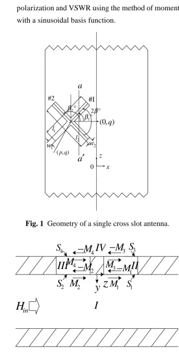
Fig. 1 Geometry of a single cross slot antenna.
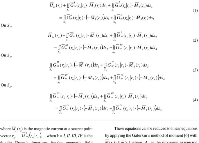
Fig. 2 Magnetic currents on the cross slot.
in
H
2M
2S
I
z
y
M
1S
1II
III
1M
−
3M
3S
3M
−
IV
4S
4M
−
2M
−
4M
2. Theory
Fig. 1 shows the geometry of a single offset cross slot in the broadwall of rectangular waveguide with finite length. It consists of the superimposition of slot
#1 (length l1 and width w1) and slot #2 (length l2 and
width w2) with the common geometry center, equal
offset p and crossing angle 2b.
Before analyzing, the following assumptions were made: (a) the waveguide wall is perfectly conducting, (b) an infinite plane of perfect electric conductor is placed at the external surface of the waveguide wall, and (c) all rectangular slots are very narrow so that the electrical field on each slot aperture has only a component in the direction of
(
)
(
)
∫∫ ⋅(
−)
∫∫ ⋅ − + = ∫∫ ⋅ + ∫∫ ⋅ − 4 3 4 2 4 4 3 3 4 4 2 2 ) ( ) ( ) ( ) ( ) ( ) ( ) ( ) ( S s s o IV m S s s o IV m S s s o III m S s s o III m ds r M r r G ds r M r r G ds r M r r G ds r M r r G(
)
∫∫ ⋅ ∫∫ ⋅ − + = ∫∫ ⋅ + ∫∫ ⋅ + 3 1 2 1 3 3 1 1 2 2 1 1 ) ( ) ( ) ( ) ( ) ( ) ( ) ( ) ( ) ( S s s o II m S s s o II m S s s o I m S s s o I m o in ds r M r r G ds r M r r G ds r M r r G ds r M r r G r H(
)
∫∫ ⋅ ∫∫ ⋅ − + = ∫∫ ⋅ + ∫∫ ⋅ + 4 2 2 1 4 4 2 2 2 2 1 1 ) ( ) ( ) ( ) ( ) ( ) ( ) ( ) ( ) ( S s s o III m S s s o III m S s s o I m S s s o I m o in ds r M r r G ds r M r r G ds r M r r G ds r M r r G r H(
)
(
)
∫∫ ⋅(
−)
∫∫ ⋅ − + = ∫∫ ⋅ + ∫∫ ⋅ − 4 3 3 1 4 4 3 3 3 3 1 1 ) ( ) ( ) ( ) ( ) ( ) ( ) ( ) ( S o s s IV m S o s s IV m S o s s II m S o s s II m ds r M r r G ds r M r r G ds r M r r G ds r M r r G On S1, (1) On S2, (2) On S3, (3) On S4, (4) the slot width.The analysis model is divided into four regions; the waveguide region (region I), the wall-thickness regions (regions II and III) and the half-space region (region IV), as shown in Fig. 2. According to the field equivalent theorem, all cross slot apertures can be replaced by unknown equivalent magnetic currents
Mj , where j = 1, 2, 3, 4. If the cross slot apertures between
waveguide and wall-thickness regions of the slot #1
and #2 are denoted by S1 and S2, respectively and that
between the half-space and wall-thickness regions are
denoted by S3 and S4, respectively, the continuity
conditions for the tangential magnetic fields on the apertures can be written into integral equations as
These equations can be reduced to linear equations by applying the Galerkin’s method of moment [6] with
Mj(rs)=Ajmj(rs) where Aj is the unknown expansion
coefficient, mj(rs) is the basis function and mi(r0) is the
weighting function. Therefore, the linear equations can be obtained as the following
(5) 1 3 13 2 12 1 11 11 ) (YI +YII A +YIA −YIIA =−B
where Mj (rs) is the magnetic current at a source point
vector rs, , , when k = I, II, III, IV, is the
dyadic Green’s functions for the magnetic field produced by a unit magnetic current in the region
k (I is an infinitely long waveguide, II and III is a cavity, IV is a half free space and r0 is an observation point
vector), and Hin (r0) is the scattered magnetic field by
the slot apertures.
(
o s)
k m r r(6)
(7)
(8)
These can be written in a matrix form as
(9) where
(10)
(11)
Solving equation (9) will provide the unknown
expansion coefficient Aj, the useful value for determining
the electric fields and reflection coefficient of the antenna.
The electric fields can be determined as
On slot#1 (12) (13) On slot#2 (14) (15) (16) (17) (18)
By using superposition, these electric field parameters can be written as
(19)
(20)
Therefore, the axial ratio (AR) can be expressed as
(21)
where
(22)
(23)
The reflection coefficient (S11) and the transmission
coefficient (S21) can be found as
(24)
(25)
where is the scattered magnetic field in ± z
direction at TE10 mode.
The rational radiation power of cross slot is represented as
(26)
The input characteristic impedance (Zin) can be
calculated from
(
E
θjE
φ)
E
r=
+
2
1
(
E jE)
. El = θ − φ 2 1 2 1 θ θ θ E E E = +.
E
E
E
φ=
φ1+
φ2 l r l r E E E E AR − + = i y i y i x i x i x i y w k w k l k l jk l jk l f ) 2 ( sin 2 ) ( ) 2 ( exp ) 2 ( exp 2 2− − − − − = π π ) cos( sin 0 d d i x k k =θ
φ
−φ
). sin( sin 0 d d i y k k =θ
φ
−φ
0 ) ( 33 33 3 34 4 1 31 + + + = −YIIA YII YIV A YIVA . A Y Y A Y A Y42III 2+ 43IV 3+( 44III + 44IV) 4 =0 − − − = ⋅ + − + − − + − + 0 0 0 0 0 0 2 1 4 3 2 1 44 44 43 42 34 33 33 31 24 22 22 21 13 12 11 11 B B A A A A Y Y Y Y Y Y Y Y Y Y Y Y Y Y Y Y IV III IV III IV IV II II III III I I II I II I∫∫∫∫
⋅ ⋅ = i j S S o s s j s o k m o i k ij m r G r r m r dsds Y ( ) ( ) ( ) . ds r H r m B i S o o in o i i =∫∫ ( )⋅ ( ) ) ( sin )] sin cos ( sin [ exp ) ( exp 2 0 0 0 3 1 i d y d i d i d f q p jk r r jk jk A E φ φ φ φ θ π θ − + ⋅ − = ) ( cos cos )] sin cos ( sin [ exp ) ( exp 2 0 0 0 3 1 i d d y d i d i d f q p jk r r jk jk A E φ φ θ φ φ θ π φ − + ⋅ − = ) ( sin )] sin cos (pi φd +qi φd fy φd −φi ) ( cos cos )] sin cos (pi φd +qi φd fy θd φd−φi ⋅ + ⋅ =∫∫
+∫∫
+ 2 1 2 ) ( 10 2 2 1 ) ( 10 1 1 11 ( ) ( ) 2 1 S s S s H ds A m r H ds r m A S ⋅ + ⋅ + =∫∫
−∫∫
− 2 1 2 ) ( 10 2 2 1 ) ( 10 1 1 21 ( ) ( ) 2 1 1 S s S s H ds A m r H ds r m A S ) ( 10 ± H.
S
S
112 2121
−
−
2 4 24 2 22 22 1 21A (Y Y )A Y A B YI + I + III − III =− sin [ exp ) ( exp 2 0 0 0 4 2 jk d r r jk jk A E θ π θ ⋅ − = sin [ exp ) ( exp 2 0 0 0 4 2 jk d r r jk jk A E θ π φ ⋅ − = where(27)
where Z0 is the system characteristic impedance (50 W)
and S11 is the reflection coefficient.
3. Numerical and Experimental Results
In this research, the chosen basis function was
(28)
By using the dyadic Green’s function in the virtual cavity [7] to analyze equation (9), the unknown expansion coefficients were obtained. A standard X-band
waveguide was used as a model antenna. MATLABâ
program was utilized to solve the optimized cross slot parameters for the minimum axial ratio and VSWR at operating frequency around 8.7 GHz. Figs. 3 and 4 show the calculated axial ratios and the reflection
coefficients as functions of offset (p1 = p2 = -2.6, -3.0,
-3.4 and -3.8 mm) and crossing angle values (2b = 100o
to 120o). In Fig. 3, the minimum axial ratio values are
found at different crossing angles corresponding to each offset.
The optimized cross slot parameters of antenna
were found to be l1 = l2 = 14.5 mm, w1 = w2 = 1.5 mm,
p1 = p2 = -3.8 mm and 2b = 104o. The antenna was
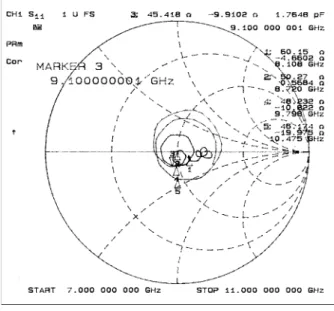
then constructed and terminated with a matched waveguide load at one end. The axial ratio was carefully measured to be 1.09. The VSWR and characteristic impedance of the antenna were also tested at the frequency range from 7.0 to 11.0 GHz by using a network analyzer, as the results shown in Figs. 5 and 6. The measured VSWR and characteristic impedance at frequency of 8.7 GHz were obviously
obtained to be 1.01 and 50.27 + j.057 W, respectively.
Finally, the percent of radiation power from the incident power as a function of slot length was calculated and measured, as results shown in Fig. 7, indicating a very good agreement.
Fig. 3 Calculated axial ratio with l1 = l2 = 14.5 mm
and w1 = w2 = 1.5 mm.
Fig. 4 Calculated VSWR with l1 = l2 = 14.5 mm
and w1 = w2 = 1.5 mm.
Fig. 5 Measured VSWR at frequency range from
7.0 to 11.0 GHz. 0 11 11 ) 1 ( ) 1 ( Z S S Zin ⋅ − + =
( )
x l x. l w r m j j j j s j ∧ + = 2 sin 1 π 100 105 110 115 120 0.9 1.0 1.1 1.2 1.3 1.4 1.5 1.6 1.7 1.8 1.9 2.0 2.1 A x ia l R ati oCrossing Angle (degree) p = -2.6 mm p = -3.0 mm p = -3.4 mm p = -3.8 mm 100 105 110 115 120 1.00 1.05 1.10 1.15 1.20 1.25 1.30 1.35 VS W R
C rossing A ngle (degree)
p = -2.6 m m p = -3.0 m m p = -3.4 m m p = -3.8 m m
4. Conclusions
The method of moment was used to analyze the antenna for the optimized cross slotted parameters. With these parameters, the antenna was built and tested. The results from calculation are in good agreement with real experiments at the operating frequency around 8.7 GHz, which verifies the accuracy of this method. The minimum axial ratio of 1.09 and VSWR of 1.01 were reported. The constructed antenna demonstrates a
broad operating frequency band (³ 2 GHz) and high
efficiency (³ 14 % radiation power). The antenna
efficiency is expected to be drastically improved by increasing a number of cross slots as an antenna array.
Fig. 6 Measured characteristic impedance at
frequency range from 7.0 to 11.0 GHz.
Fig. 7 Calculated and measured radiation powers
as a function of slot length.
5. Acknowledgment
This work has been supported by the Japan Society for Promotion of Science (JSPS) and the Thailand’s National Science and Technology Development Agency (NSTDA). The authors would like to express sincere gratitude to Prof.Dr. Jiro Hirokawa and Prof.Dr. Makoto Ando at Tokyo’s Institute of Technology for their invaluable advice and suggestion on this research.
References
1. Khac, T. V. and Carson, C. T. “Impedance
properties of a longitudinal slot antenna in the broad face of a rectangular waveguide.” IEEE
Trans. Antennas Propagat. 21, 9 (Sep. 1973):
708-710.
2. Lyon, R. W. and Sangster, A. J. “Efficient moment
method analysis of radiating slots in a thick-walled rectangular waveguide.” IEE Proc. Part H. 128, 4 (Aug. 1981): 197-205.
3. Stern, G. J. and Elliott, R. S. “Resonant length
of longitudinal slots and validity of circuit representation: theory and experiment.” IEEE
Trans. Antennas Propagat. 33, 11 (Nov.1985):
1264-1271.
4. Rengarajan, S. R. “Compound radiating slots in
a broad wall of a rectangular waveguide.”
IEEE Trans. Antennas Propagat. 37 (Sep.
1989): 1116-1123.
5. Hongyu, L., Zhenghe, F. and Qiji, Y.
“Analysis of an offset cross slot in the broadwall of rectangular waveguide using the Galerkin method.” IEEE Trans.
Antennas Propagat. Int. Symp. l.3 ( Jun.
1998): 1702-1705.
6. Harrington, R. F. Field Computation by
Moment Methods. Robert E. krieger Publishing,
1982.
7. Hirokawa, J., et al. “Matching slot pair for a
circularly polarized slotted waveguide array.” IEE
Proc. Part H. 137, 6 (Dec. 1990).
12.8 13.0 13.2 13.4 13.6 13.8 14.0 14.2 14.4 14.6 10 12 14 16 18 20 Ra di a ti o n Pow e r (% ) Slot Length (mm ) Calculate M easure