Position Control of 1-DOF High-Precision Rotary Table using
Adaptive Neuro-Fuzzy Inference System (ANFIS) Controller
Hendri Maja Saputra1), Abdurrahman Nurhakim2), Sapdo Utomo3)
Research Center for Electrical Power and Mechatronics1,3)
Indonesian Institute of Sciences
Jl. Cisitu No.21/154D Sangkuriang - Bandung 40135, Indonesia Department of Electrical Engineering 2)
UIN Sunan Gunung Djati Bandung
Jalan A.H Nasution 105, Cibiru - Bandung 40614, Indonesia Email: [email protected]), [email protected]2),
Received May 22, 2019; Revised August 28, 2019; Accepted October 24, 2019
Abstract
Research of position control of 1-DOF high-precision rotary table using adaptive Neuro-Fuzzy inference system (ANFIS) controller has been done. In the closed-loop system without a controller, the response was oscillating and pounding caused by inertial torque. It because a rotary table receives a considerable load. Based on this, the ANFIS controller is needed to eliminate oscillations and compensate for the inertia. The result shows that there was no oscillation or overshoot with the steady-state error value of 2.27% for the reference angle of 45°, valued at 0.10% reference angle of 180°, and valued at 0% reference angle of 360°. The result proves that ANFIS controllers can eliminate oscillations with and compensate for inertia.
Keywords: ANFIS, position control, BLDC motor, rotary table,
response time.
1. INTRODUCTION
The rotary table has been widely used in many areas such as synthetic aperture radar System (SAR)[1], industrial applications[2][3][4][5][6], calibration tools[7][8][9], transportation systems[10] and so on. In order to get a satisfactory result, the rotary table has to meet high precision output which in this case is an accurate position of determined angle. Nevertheless to get high precision of position angle is not easy. Many problems to be addressed, such as dynamic friction and dynamic load. These problems have an effect on
increasing the steady-state error and the nonlinearity problem[11]. As like general rotary table platform, a motor was used for the main actuator of the system. In this research, Brushless DC (BLDC) motor has chosen for the actuator. BLDC motor has advantages in lower noise, more reliable, higher torque, more efficient and smaller than Brushed DC motor [12][13][14] so it will solve any problems that brushed DC motor cannot handle. An experiment in the closed-loop system without controller has been conducted, and the result showed the response was oscillating and pounding caused by inertial torque. It because a rotary table receives a considerable load.
One of the valid methods to composite for the nonlinearity is to apply nonlinear control algorithm [11], and adaptive controls are still one of popular option in the scientific world [11] [14][15][16]. The adaptive control system method used in this research was an Adaptive Neuro-Fuzzy Inference System (ANFIS). To achieve high precision of angle of the rotary table, various closed-loop motor controls have been developed in previous research.
This research focuses on the implementation of ANFIS control system on the rotary table to reduce the oscillations on BLDC motor.
2. RELATED WORKS
The research using ANFIS has been done in several previous works such as in the paper [17], where the ANFIS controller was used for bipedal robot control to determine the movement of the robot's legs using a neuro-fuzzy technique. The other research related to the application of ANFIS control system was also carried out on paper [18], where the ANFIS control system was used for 6-DoF Robot Arm control.
ANFIS can be used to generate a trajectory on the excavator's arm [19]. The trajectory was designed at several special points, then inverse kinematics were used to determine the movement angle of the arm through determined points in the joint space. The ANFIS control system serves to smoothen arm movements. In paper [20], ANFIS-Inverse-Controlled was used to overcome the complex movement of the PUMA 560 3-DoF robot at all angles of the robot joint.
3. ORIGINALITY
Most of the previous research about ANFIS control system was used to perform speed control. The main contribution of this paper is to overcome the problem of the BLDC motor response on the rotary table position using ANFIS control system, where the BLDC motor was oscillating and pounding caused by inertial torque. It because a rotary table receives a considerable load. The use of ANFIS control system on the BLDC motor can increase the accuracy and precision of the rotary table position. The biggest advantage of using ANFIS controller is better accuracy rate than other controllers, Its also good to be applied to the nonlinear system [21]. The results of this study are expected to contribute on the fields of militaries, industrial applications, calibration tools,
transportation systems, and other fields that require a rotary table with high level of precision and accuracy.
4. SYSTEM DESIGN
4.1. ANFIS Controller Design
In this research, input on ANFIS system was calculated in the form of error (e) and derivative error (de) and the output of ANFIS system is speed which sent in the form of PWM signal. The equation (1) and equation (2) showed the calculation of error and derivative error (de) that was used in this research.
= − (1)
= [ ( − )]/ (2)
where θref is the reference angle, θ is the position of the actual angle, and dt is sampling time.
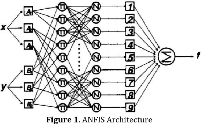
The ANFIS architecture used consists of two entries with nine rules, and each input has three membership sets. Figure 1 shows the ANFIS Architecture of this research.
Figure 1. ANFIS Architecture
Based on Figure 1, ANFIS architecture consists of layers described as follows:
Layer 1: in this layer, each input was mapped according to the classification.
Each node in this layer is adaptive with membership set of errors (e) and derivative error (de)[22],
= ( ) = 0 ≤ ≤ ≤ ≤ ≤ ≤
(3)
= ( ) = 0 ≤ ≤ ≤ ≤ ≤ ≤ (4)
Layer 2: there were nine rules in this layer. Each node in this layer represents
the activation level, which presented in the equation(5) [22][23],
= = ( ). ( ) (5)
Layer 3: the node in this layer calculates the ratio of total activation level,
which described in the equation (6) [22][23],
= =
⋯ (6)
Layer 4: adaptive node i in this layer calculates the combination of the rule. In
this layer, there are tree parameters (pi, qi, ri) whose values can be set according to the plant output. The equation (7) describes the calculation of the output [22][23],
= = ( . + . + ) (7)
where is the output of layer 3, and {pi, qi, ri} is the parameter set,
Layer 5: in this layer, all output from the fourth layer would be calculated by
adding the total signal output [22][23],
= ∑ =∑∑ (8)
Equations (5) to equation (8) were substituted as described in equation (9),
= Σ = Σ ( ). ( ) ( . + . + ) (9)
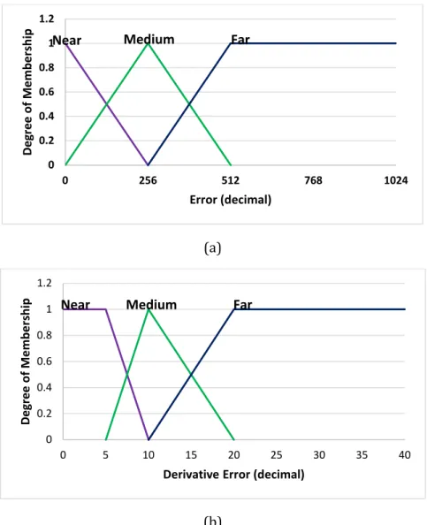
In this research, the membership functions used were triangles shape. Each input is mapped according to the classification chosen with linguistic variables (near, medium, far) that were used to describe each input condition[24] . The membership sets of error (e) and derivative error (de) were shown in Figure 2.
(a)
(b)
Figure 2. membership functions of (a) error (e) and (b) derivative error (de).
Based on Figure 2, there are two types of membership, namely error (e) and derivative error (de). In the clustering error process, the near condition the membership value is 1 to 0, for bit error range of 0 to 256. In the medium condition the membership value is 0 to 1, for bit error range of 0 to 256, and 1 to 0 for bit error range of 256 to 512. In far condition, the membership value is 0 to 1 for the bit error range of 256 to 512, and 1 for the 512 error bit range to 1023.
In the clustering process of derivative error, the near condition of membership value is 1 for derivative error range of 0 to 5, and 1 to 0 for the range 5 to 10. In medium condition, the membership value is 0 to 1 for derivative error range of 5 to 10, and 1 to 0 for derivative error range of 10 to 20. In far condition, the membership value is 0 to 1 for derivative error range of 10 to 20 and 1 for derivative error range of 20 to 40.
0 0.2 0.4 0.6 0.8 1 1.2 0 256 512 768 1024 Degree o f Me m be rship Error (decimal)
Near Medium Far
0 0.2 0.4 0.6 0.8 1 1.2 0 5 10 15 20 25 30 35 40 Degree o f Me m be rship
Derivative Error (decimal)
4.2 Hardware Design
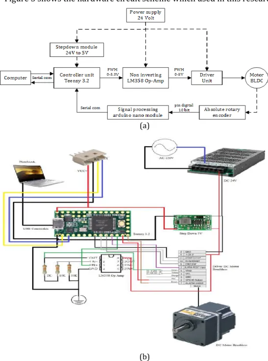
Figure 3 shows the hardware circuit scheme which used in this research.
(a)
(b)
Figure 3. Schematic circuit: (a) component scheme; and (b) wiring scheme
In this research, Teensy 3.2 was used as the controller unit. The controller unit receives feedback in the form of angular position data from absolute rotary encoder, which has previously been processed first on Arduino nano to converting the binary to decimal data. The type of absolute rotary encoder
which used is EP50S8-1024-2F-P-24. The angular position data was used as the actual value for the ANFIS control system to correct the reference value.
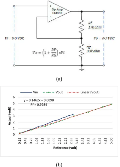
The output of the ANFIS control system was used to generate PWM pulses as input for the BLDC motor driver, where the PWM works at a frequency of 488.28 Hz. The type of BLDC motor which used is AXH5100KC-5 and the type of driver which used is AXHD100K. BLDC motor drivers require a voltage from 0 to 5 Volt to control speed, but the maximum voltage output of the pulse signal pin on the Teensy 3.2 is 3.3 Volt. It requires a signal amplifier circuit (non-inverting amplifier) to increase the voltage to 5 Volt. LM358 used as an op-amp on amplifier circuit. Figure 4 shows the schematic of the non-inverting amplifier circuit.
(a)
(b)
Figure 4. Non-inverting op-amp: (a) circuit scheme; and (b) output performance y = 0.1462x + 0.0098 R² = 0.9984 0 1 2 3 4 5 6 0.1 5 0.4 5 0.7 5 1.0 5 1.3 5 1.6 5 1.9 5 2.2 5 2.5 5 2.8 5 3.1 5 3.4 5 3.7 5 4.0 5 4.3 5 4.6 5 5.0 0 A ctual (volt ) Reference (volt)
Based on the circuit scheme in Figure 4 (a), the components used include the LM358 op-amp, resistor with value of 17K Ohm and 33K Ohm. In Figure 4 (b), the performance of the module looks linear with a linear regression value of R is 0.9984.
5. EXPERIMENT AND ANALYSIS
Figure 5 below describes the experimental set-up in this research.
Figure 5. Experimental Set-up
Based on Figure 5, the experiment was carried out on the body of the rotary table, which was controlled using Teensy 3.2 via the BLDC motor type AXH5100KC-5. The BLDC motor itself was operated using the AXH5D100K Motor Driver. The experiment was done by looking at how fast the response from a DC motor to reach a predetermined position. In this research, the input references used were 45 °, 90 °, 135 °, 180 °, 225 °, 270 °, 315 °, and 360°.
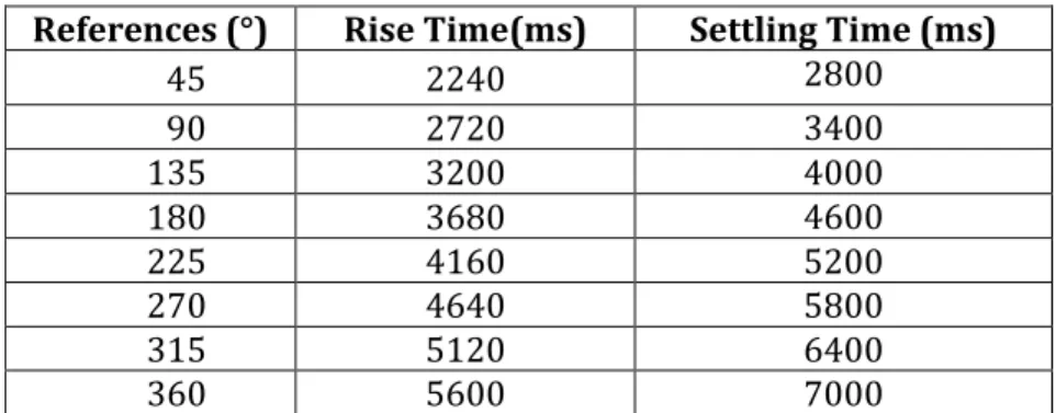
The quality of the control system response can be seen from the values of rising time and settling time. Rise time was the motor traveled time to reach the 2% tolerance band while settling time was the motor traveled time to reach steady-state condition. Rise time would be recorded when the motor has reached 98% of reference angle and the settling time would be recorded when the motor has reached steady-state condition. Table 1 presents the value of rise time and settling time in millisecond units.
Table 1. BLDC motor response with ANFIS Controller
References (°) Rise Time(ms) Settling Time (ms)
45 2240 2800 90 2720 3400 135 3200 4000 180 3680 4600 225 4160 5200 270 4640 5800 315 5120 6400 360 5600 7000
Based on Table 1, for a 45° reference angle, the rise time value was 2240 ms and the settling time value was 2800 ms, for 90° reference angle, the rise time value was 2720 ms and settling time value was 3400 ms, for 135° reference angle, the rise time value was 3200 ms and the settling time value was 4000 ms, for 180° reference angle, the rise time value was 3680 ms and the settling time value was 4600 ms, for 225° reference angle, the rise time value was 4160 ms and the settling time value was 5200 ms, for 270° reference angle, the rise time value was 4640 ms and the settling time value was 5800 ms, for 315° reference angle, the rise time value was 5120 ms and the settling time value was 6400 ms, and for 360° reference angle, the rise time value was 5600 ms and the settling time value was 7000 ms.
Three reference angle of experiment response signals were taken as a sample and presented in graphical form, namely 45°, 180°, and 360°. Figure 6 presented the graph of the test results that have been done.
(a)
(b)
(c)
Figure 6. Non-Controller versus with ANFIS Controller, with References: (a) 45°; (b)180°; and (c) 360° 0.00 10.00 20.00 30.00 40.00 50.00 60.00 0 2000 4000 6000 8000 10000 Angle (degree ) Time (ms)
Non Controller ANFIS Reference
0.00 50.00 100.00 150.00 200.00 -200 4800 9800 14800 19800 Angle (degree ) Time (ms)
Based on the graph in Figure 6, there were three response signals that have been compared between non-controller and ANFIS Controller, which was a reference angle of 45°, 180°, and 360°. On the non-controller graph, the output signal looks oscillated with it has an average difference value of 7.43° on reference angle of 45 °, 7.21° on the reference angle of 180°, and 7.74° on reference angle of 360°. Based on these observed signals, the oscillations have a large band fairly, so it required a control system to reduce it. On the other hand, the test result of ANFIS Controller output signal shown that the steady-state error value for a 45° reference angle was obtained at 2.27%, then 0.10% for the 180° reference angle, and 0% for 360° reference angle. That means the percentage of oscillations reduced by the controller is 16.51%, 4.01%, and 2.15% on the reference angle of 45°,180°, and 360° respectively. According to these results, the ANFIS Controller could fix the oscillation of the rotary table compared with the non-controller system.
6. CONCLUSION
Based on the result, an applied of ANFIS controller produced neither oscillation nor overshoot with the steady-state error value of 2.27%, 0.10%, and 0% for reference angle 45°, 180°, and 360° respectively. Therefore, it can be concluded that the rotary table controlled by an Adaptive Neuro-Fuzzy Inference System (ANFIS) shows a better response by eliminating overshoot and oscillation. So, high-level accuracy and precision of the rotary table could be achieved in this research.
Acknowledgments
We would like to thank Jeremiah Aria Setiana who helped in making the rotary encoder reader module, Virgilius Galih who helped in recording experiment data, and Mr. Rahmat who modified the mechanical device from the rotary table. Great respect for teammates in the Industrial Automation Research Group for permitting us to use the room for doing the experiment, and we also thank the Chairman of Research Center of Electrical Power and Mechatronics - LIPI who has realized the research budget as implied in the 2015-2019 research road-map.
REFERENCES
[1] C. Xu, Y. Li, Q. Liu, Y. Huang, H. Wang, and Y. Xia, Target Detection Based
on a Rotary Table-Mounted Synthetic Aperture Radar System, in
22nd International Conference on Digital Signal Processing (DSP), 2017.
[2] Y. Jiao, Z. Dong, Y. Ding, and P. Liu, Optimal arrangements of scanning
heads for self-calibration of angle encoders, IOP Sci., vol. 28, no. 10,
2017.
[3] F. W. Huo, D. M. Guo, G. Feng, R. K. Kang, and R. L. Wang, A new kinematics for ultra precision grinding of conical surfaces using a
45, 2012.
[4] A. T. M. Willemsen, C. Frigo, and H. B. K. Boom, Lower extremity angle
measurement with accelerometers - error and sensitivity analysis,
IEEE Trans. Biomed. Eng., vol. 38, no. 12, pp. 1186–1193, 1991.
[5] B. Denkena, D. Dahlmann, F. Floeter, and T. Bruehne, Conceptual design
for electromagnetic guided rotary table in machine tools, in
Procedia CIRP, 2014, vol. 24, no. Mic, pp. 80–85.
[6] F. Huo, D. Guo, Z. Li, G. Feng, and R. Kang, Generation of rotationally symmetric surfaces by infeed grinding with a rotary table and a cup
wheel, Precis. Eng., vol. 37, no. 2, pp. 286–298, 2013.
[7] W. Kokuyama, T. Watanabe, H. Nozato, and A. Ota, Measurement of Angle Error of Gyroscopes Using a Rotary Table Enhanced by
Self-calibratable Rotary Encoder, in International Symposium on Inertial
Sensors and Systems (ISISS) Proceedings, 2015, pp. 0–3.
[8] J. S. Lee, S. W. Jang, J. G. Choi, and T. G. Lee, North-Finding System using
Multi-Position Method with a 2-Axis Rotary Table for a Mortar, no.
c, pp. 1–6, 2016.
[9] R. V Ermakov, Angular Velocity Estimation of Rotary Table Bench Using Aggregate Information from the Sensors of Different Physical
Nature, in Conference of Russian Young Researchers in Electrical and
Electronic Engineering (EIConRus), 2017, pp. 820–825.
[10] K. Ito, W. Maebashi, J. Ikeda, and M. Iwasaki, Fast and Precise Positioning of Rotary Table Systems by Feedforward Disturbance
Compensation Considering Interference Force, in 37th Annual
Conference of the IEEE Industrial Electronics, 2011, pp. 3382–3387.
[11] J. Mo, Z. Qiu, J. Wei, and X. Zhang, Adaptive positioning control of an
ultrasonic linear motor system, Robot. Comput. Integr. Manuf., vol. 44,
pp. 156–173, 2017.
[12] R. Rahmayanti, S. Utomo, H. M. Saputra, Effect of Digital PWM
Command Signal on Steady State Speed Response of BLDC Motor, J.
Teknol. Indones., vol. 38, no. 3, 2015.
[13] M. R. Faieghi and S. M. Azimi, Design an Optimized PID Controller for Brushless DC Motor by Using PSO and Based on NARMAX Identified
Model with ANFIS, in 12th International Conference on Computer
Modelling and Simulation, 2010, no. 1, pp. 1–6.
[14] K. Premkumar and B. V Manikandan, Speed control of Brushless DC
motor using bat algorithm optimized Adaptive Neuro-Fuzzy
Inference System, Appl. Soft Comput. J., vol. 32, pp. 403–419, 2015.
[15] D. M. Karantonis, M. R. Narayanan, M. Mathie, N. H. Lovell, and B. G. Celler, Implementation of a real-time human movement classifier
using a triaxial accelerometer for ambulatory monitoring, IEEE
Trans. Inf. Technol. Biomed., vol. 10, no. 1, pp. 156–167, 2006.
[16] A. M. Zaki, M. El-bardini, F. A. S. Soliman, and M. Mabrouk, Embedded two level direct adaptive fuzzy controller for DC motor speed
[17] H. Wongsuwarn and D. Laowattana, Neuro-Fuzzy Algorithm for a
Biped Robotic System, vol. 10140, no. 3, pp. 858–864, 2008.
[18] W. M. Jasim and E. T. Yassen, High Order Robotics ARM Modelling
Based on ANFIS Technique, J. Engginering Appl. Sci., vol. 12, no. 9, 2017.
[19] N. T. Vu, N. P. Tran, and N. H. Nguyen, Adaptive Neuro-Fuzzy Inference
System Based Path Planning for Excavator Arm, J. Robot., vol. 2018,
p. 7, 2018.
[20] Y. I. Al and M. Mieee, ANFIS-Inverse-Controlled PUMA 560
Workspace Robot with Spherical Wrist, in International Symposium
on Robotics and Intelligent Sensors 2012 (IRIS 2012), 2012, vol. 41, pp.
700–709.
[21] A. V Gite, R. M. Bodade, and B. M. Raut, ANFIS Controller And Its
Application, Int. J. Eng. Res. Technol., vol. 2, no. 2, pp. 1–5, 2013.
[22] B. A. A. Omar, A. Y. M. Haikal, and F. F. G. Areed, Design adaptive
neuro-fuzzy speed controller for an electro-mechanical system, Ain Shams
Eng. J., vol. 2, no. 2, pp. 99–107, 2011.
[23] J. R. Jang, ANFIS : Adaptive-Network-Based Fuzzy Inference System, vol. 23, no. 3, pp. 665–685, 1993.
[24] I. Ferdiansyah, E. Purwanto, and N. A. Windarko, Fuzzy Gain Scheduling of PID ( FGS-PID ) for Speed Control Three Phase
Induction Motor Based on Indirect Field Oriented Control ( IFOC ),