Tribocorrosion and Electrochemical Behavior of DIN 1.4110 Martensitic Stainless Steels
After Cryogenic Heat Treatment
Leandro Brunholi Ramosa*, Leonardo Simonia, Rafael Gomes Mielczarskia, Maria Rita Ortega Vegaa, Roberto Moreira Schroedera, Célia de Fraga Malfattia
Received: May 02, 2016; Revised: December 15, 2016; Accepted: January 25, 2017
DIN 1.4110 martensitic stainless steel is largely used in the cutlery industry due to its high corrosion resistance associated with high mechanical resistance. However, when this material works under
corrosion and wear conditions at the same time, their synergistic effect can accelerate the degradation
process of the alloy. Cryogenic heat treatments have been proposed to improve the dimensional stability and mechanical properties, since they minimize the amount of retained austenite. The aim of this
work is to study the effect of deep cryogenic heat treatment at -80 ºC and at -196 ºC on the corrosion
resistance and tribocorrosion behavior of DIN 1.4110 martensitic stainless steel. The microstructure,
hardness, corrosion resistance and tribocorrosion behavior were evaluated. Although the heat-treated
samples presented higher hardness and lower corrosion current density (icorr) compared to samples in spheroidized condition, their material removal under tribocorrosion conditions increased, which demonstrated the synergy between corrosion and wear.
Keywords: DIN 1.4110; Cryogenic heat treatments; Corrosion; Tribocorrosion
* e-mail: leandrobrunholi.lbr@gmail.com
1. Introduction
DIN 1.4110 martensitic stainless steel is used extensively in general cutlery (i.e. food processing blades and cutting tools) due to its high corrosion and mechanical resistance, as well as high hardness and wear resistance1. This steel has a chemical composition similar to that of AISI 420 martensitic stainless steel, although its carbon content is higher. This alloy has an arrangement in carbon and chrome content to extend
the “gamma loop”; when heated to the austenitic phase field and fast cooled, it produces a martensitic microstructure - a
metastable microstructure that confers high hardness and wear resistance.
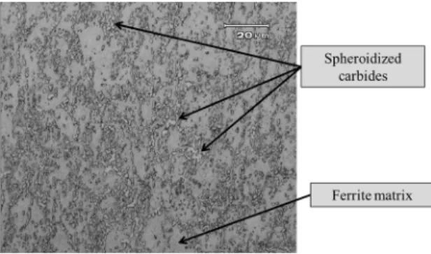
As spheroidized, DIN 1.4110 stainless steel shows a microstructure consisting of dispersed spheroidized carbides in a matrix of ferrite, resulting in an average hardness of 200 HV2.
Martensitic stainless steel (AISI 420, AISI 410, AISI 416 and AISI 403, for example) shows good corrosion resistance compared to low alloy steels. However, the martensitic stainless steel corrosion resistance is lower than that of austenitic and
ferritic steels. In particular, super-ferritic stainless steels present
an enhancement of their corrosion resistance because of the high chromium content that works as a ferrite stabilizer3. Hardness and wear resistance can be crucial for certain applications such as gas turbine blades4. Following this trend, some studies have proposed the plasma nitriding process and the addition of alloying elements such as nitrogen, nickel and molybdenum to increase corrosion and wear resistance3,5-7.
DIN 1.4110 martensitic stainless steel is largely used in the cutlery industry as cutting blades, which has motivated studies aiming to characterize and improve the tribological
properties of these materials. The combined corrosion-wear effect can result in serious problems for materials under wear and corrosion conditions. If wear (mechanical effect) and corrosion (chemical or electrochemical effect) processes act
simultaneously, it can lead to an enhanced level of material
loss due to their synergic effect8.
The studied material does not present a 100% martensitic microstructure after conventional quenching due to its high alloying elements and carbon content9. However, cryogenic
treatments are an option to increase martensite content after conventional quenching. As a consequence of the greater content of martensite, these treatments confer to the steel an increase in dimensional stability, hardness, and wear and fatigue resistance10-13. Cryogenic treatments are usually
carried out at -80 ºC and -196 ºC, corresponding to dry ice
sublimation temperature and liquid nitrogen boiling temperature, respectively12. Such treatments can influence the amount of retained austenite inside the steel, considering that the lower temperature of the treatment, depending on the steel martensite
finish (Mf) line, induces the transformation of a higher amount of austenite to martensite; consequently, a lower fraction of
retained austenite will remain in the steel. This can influence
the steel’s properties, since it is softer than martensite, reduces the dimensional precision of the components, and also shows a
different corrosion behavior compared to the martensitic matrix.
a Corrosion Research Laboratory - LAPEC, Federal University of Rio Grande do Sul - UFRGS,
Tempering temperature also plays an important role in retained austenite content. Besides stress relieving and hardness decrease, using an appropriate tempering temperature can lead to a decrease of its fraction, since this treatment transforms the retained austenite into ferrite and cementite14.
The main objective of this study is to interrogate the
influence of cryogenic heat treatment (-80 ºC and -196 ºC)
on the electrochemical and tribocorrosion behavior of DIN 1.4110 martensitic stainless steel.
2. Experimental
2.1. Materials
The material tested was DIN 1.4110 martensitic stainless steel, with chemical compositions shown in Table 1.
and polished to a 1 µm finish before being immersed in Marble
etchant (10 g CuSO4, 50 ml HCl and 50 ml H2O) to reveal any martensite and carbides present within the DIN 1.4110 martensitic stainless steel microstructure.
Three micro-hardness maps of the martensitic stainless
steel samples were measured using a Vickers microhardness tester (Tukon 2100 B) with a load of 1 kgf for 15 s.
Surface roughness measurements were performed with
a stylus profilometer (MarSurf XCR20) as standard ISO 12085:1998 at a load of 0.02 N cut-off of 0.8 mm and stylus
velocity of 0.5 mm.s-1 (11218 point measurements). The
roughness Ra (arithmetical average height (µm)), Rz (10-point
height (µm) and Rt (maximum height of the profile (µm))
values were measured29.
2.4. Corrosion test
Polarization curves, obtained in AUTOLAB PGSTAT 302N Potentiostat/Galvanostat equipment, were used to characterize the corrosion resistance of DIN 1.4110 martensitic
stainless steel in the as-received and heat-treated conditions
(Table 2). Table 3 shows the parameters used to characterize the corrosion resistance.
2.5. Tribocorrosion test
Sliding ball-on-flat wear tests under dry conditions and in
the presence of corrosive medium conditions (tribocorrosion) were carried out on the DIN 1.4110 martensitic stainless
steel in the as-received condition and with heat treatments
(Table 2). The tests were performed using a CETR Universal Material Tester (UMT) wear tester. The parameters used are shown in Table 4.
The conditions shown in Table 4 are necessary to evaluate
the synergistic effect of corrosion and wear on the metal
degradation6,15. Despite the wear test parameters (viz. normal load, frequency and stroke length) being similar in order to
compare the results, the studied parameters (Table 4) are different to those suggested by the standard ASTM G133-05: 201016.
Mathew et al.15 performed their study with low normal
load in the wear test to observe the synergistic effect of
corrosion and wear. Other authors8 also proposed to study
wear resistance with protective oxide films under low load values, because these films are brittle and thin; therefore, low
Table 1. Chemical composition in % weight of DIN 1.4110 martensitic
stainless steel of work material.
C Cr Si Mn Mo S P Fe
0.58 14.39 0.36 0.35 0.62 <0.001 <0.018 Balance
Samples were cut from LASER in a square section of 50
mm x 50 mm, and 3.5 mm thickness. The flat surfaces of the samples were wet-sanded using silicon carbide papers from 180 grit down to 600 grit.
All the tests were carried out in triplicate to ensure reproducibility.
2.2. Heat treatments
Three different heat treatments were carried out:
conventional quenching, cryogenic treatment at -80 ºC and cryogenic treatment at -196 ºC. They are all presented in
Table 2. The following tempering treatment was conducted
at 250 ºC for 1.5 hours.
Direct nebulization was applied for the cryogenic cooling. This technique consists of the nebulization of liquid nitrogen directly in a chamber using a fan. The latter allows a homogeneous temperature distribution to be obtained.
2.3. Characterization methods
The microstructure of the processed region was evaluated
using optical microscopy (Olympus CX31). The flat surfaces of the samples were wet-sanded using silicon carbide papers
Table 2. Studied samples of DIN 1.4110 martensitic stainless steel.
Sample Heat Treatments
As Received Process annealed (780 ºC and cooled in air)
Conventional Quenching 1 hour at 1080 ºC then air quenching. Following tempering treatment at 250 ºC for 1.5 hours. Cryogenic Treatment (-80 ºC) 1 hour at 1080 ºC then air quenching followed cryogenic treatment by direct nebulization in dry ice temperature (-80 ºC) for 6 hours. Following tempering treatment at 250 ºC for 1.5 hours. Cryogenic Treatment (-196 ºC) 1 hour at 1080 ºC then air quenching followed cryogenic treatment by direct immersion into liquid nitrogen (-196 ºC) for 6 hours. Following tempering treatment at 250 ºC for 1.5 hours.
Table 3. Parameters used for potentiodynamic polarization tests.
Parameters Details
Electrolyte 0.05 molL-1 NaCl
Open Circuit Potential
(OCP) monitoring 30 min
Sweep range -100 mV vs. OCP
+600 mV vs. OCP
Scan Rate 1 mV.s-1
Reference electrode Saturated calomel electrode (SCE)
Counter-electrode Platinum
Table 4. Parameters used for wear tests.
Parameters Dry Test Corrosive Medium Test
Ball (4.76 mm diameter) Alumina (Al2O3) Alumina (Al2O3)
Normal Load 2 N 2 N
Frequency 1 Hz 1 Hz
Stroke Length 2 mm 2 mm
Room Temperature 20 - 23 ºC 20 - 23 ºC
Air Relative Humidity 50% - 60% 50% - 60%
Electrolyte - 0.05 molL-1NaCl
Reference Electrode - Saturated calomel electrode (SCE)
loads must be applied to study the synergistic wear-corrosion and repassivation of the passive film.
Figure 1 shows the ball-on-flat configuration for the dry
test (a) and corrosive medium test (b). EG&G Princeton Applied Research (PAR) Potentiostat/Galvanostat equipment was used to monitor the open circuit potential (OCP) before, during, and after the wear tests (Figure 2). This methodology has been employed by other authors8,15.
Figure 1: System ball-on-flat. a) dry Test and b) corrosive medium Test.
Figure 2: Schematic set-up for tribocorrosion tests.
by a ferrite matrix with spheroidized carbides (Figure 3), as expected9.
Figure 3: Microstructure of martensitic stainless steel DIN 1.4110
in the as received condition.
The worn volume was obtained according to the ASTM
G133 - 05 (2010) standard16, section 9.3. Track profiles
were acquired with a profilometer Bruker Contour GT-K.
Then, the track area was measured using ImageJ software. Subsequently, the worn volume was calculated by multiplying this area by the stroke length.
3. Results and discussion
3.1. Microstructure
After etching with Marble solution, the sample in the
as-received condition shows a microstructure constituted
The sample quenched by the conventional heat treatment presents a microstructure composed of retained austenite and undissolved carbides distributed in a tempered martensitic matrix (Figure 4). This result has also been reported elsewhere2,9.
Figures 5 and 6 show images of samples submitted to
cryogenic quenching at -80 °C and -196 °C, respectively.
The microstructures correspond to quenched and tempered martensite with the presence of dispersed carbides and a fraction of retained austenite, as reported by other authors17.
conventional heat treatment is far from the expected Mf
temperature, which justifies the greater amount of retained austenite. The cryogenic heat treatment at -80 °C is closer
to the expected Mf line; the treatment at -196 °C is probably
under the Mf temperature. For the latter, the low air-cooling
rate during the quenching process, and the interruption of
the cooling to take the sample from air-cooling to cryogenic
cooling, can promote the austenite stabilization20. This explains the 3.01% of retained austenite in this sample, even when a temperature lower than Mf was achieved.
3.2. Hardness
The hardness values increase due to the structure
modification promoted by the different heat treatments
(Table 5). As mentioned before, the quenched and tempered samples have a tempered martensite structure and a percentage
of retained austenite, whereas the as-received sample had a
predominantly ferritic structure with spheroidized carbides.
Figure 4: Microstructuer of martensitic stainless steel DIN 1.4110
after quenching by conventional heat treatment and tempering at
250 °C for 1.5 h.
Figure 5: Microstructure of martensitic stainless steel DIN 1.4110
after cryogenic quenching at -80 °C and tempering at 250 °C for 1.5 h.
Figure 6: Microstructure of martensitic stainless steel DIN 1.4110 after
cryogenic quenching at -196 °C and tempering at 250 °C for 1.5 h.
The retained austenite content was determined using image analysis software (ImageJ). The carbide amount was
considered to be the same for the different heat treatments systems, and the reference sample corresponded to the
as-received one. The sample quenched by the conventional heat treatment achieved 6.12% of retained austenite; the content of this phase for the cryogenic quenching down to
-80 °C and -196 °C was 3.94% and 3.01%, respectively.
This result points out that the cryogenic treatment promoted the formation of less retained austenite, crucial for good dimensional stability during service18.
Medium-chrome and medium/high-carbon steels present their martensite finish (Mf) line, independent of other factors,
at roughly -120 °C19. Therefore, the sample submitted to
Table 5. Vickers microhardness values for each kind of sample
(1 kgf for 15 s).
Sample Vickers microhardness
As received 201 ± 3.7
Conventional quenching 553 ± 11.2
Cryogenic quenching (-80 ºC) 594 ± 6.3
Cryogenic quenching (-196 ºC) 612 ± 8.5
According to Farina et al.21, carbides dissolve in the austenitization step, depending on the austenitizing temperature and time. Since these parameters were common for the
different studied systems, the amount of dissolved carbides
at high temperatures during austenitizing, it is reasonable
to suppose that the final carbides content is similar among
the three heat treatments employed. As a consequence, the hardness increase can be associated with the decrease in retained austenite, which agrees with the higher amount of martensite formed during the heat treatment.
3.3. Roughness
The samples’ surface roughness values (Table 6), for all the samples after sanding with silicon carbide paper # 600, demonstrate the similar surface topography19,20.
3.4. Electrochemical behavior
The open circuit potential was monitored for 30 minutes (Figure 7). All the samples developed very similar potential values.
Figure 8 shows the potentiodynamic polarization curves
obtained in 0.05 mol.L-1 NaCl solution for all studied systems.
Table 6. Surface roughness values. Sample Ra [μm] Rz [μm] Rt [μm] As received 0.16 ± 0.04 1.19 ± 0.19 1.84 ± 0.38 Conventional quenching 0.14 ± 0.03 1.06 ± 0.19 1.73 ± 0.31 Cryogenic quenching (-80 ºC) 0.15 ± 0.03 1.13 ± 0.20 1.61 ± 0.31 Cryogenic quenching (-196 ºC) 0.13 ± 0.01 0.97 ± 0.08 1.64 ± 0.06
Figure 7: OCP monitoring in a 0.05 molL-1 NaCl solution.
polarization curves, including the corrosion potential (Ecorr) and corrosion current (Icorr) obtained by Tafel extrapolation using Nova® software, pitting potential (Epit), as well as the
passivation potential range (∆Epass). The latter can be read directly on the polarization curve, or calculated from the subtraction of Ecorr from Epit.
Figure 8: Potentiodynamic polarization curves in a 0.05 M NaCl
solution; -100 mV vs. OCP to +600 mV vs. OCP; 1 mV.s-1.
All polarization curves develop the same profile
(Figure 8), which reveals the same corrosion behavior. The
Tafel extrapolation values (Table 7) demonstrate the decrease of icorr for the heat-treated samples. However, deep heat
treatment is not steadily gaining acceptance as a process for
improving the corrosion resistance, as reported by Uygur et al.21. There is an improvement in the corrosion resistance, considering both the general and pitting corrosion, the latter being the kind of corrosion that too often attacks this class of steel22. Steels submitted to the quenching and tempering
processes have a higher pitting potential than the as-received
one. The increase in the pitting potential involved a more important passivation potential range. This behavior may be related to the decrease of spheroidized carbides amount
compared to the as-received steel (Figure 3). Carbides may
work as preferential sites for pitting corrosion initiation14. The amount of retained austenite in the studied martensitic
stainless steel DIN 1.4110 does not influence the corrosion potential, nor the pitting potential, as can be seen in Figure 8, and reported by Kimura et al.23. This is the reason why no
significant alteration of these values was observed among the different heat treatments applied and, as a consequence, among the different amounts of retained austenite in each microstructure (Figures 4-6).
3.5. Tribocorrosion behavior
Friction coefficient (COF) values were monitored for
all the samples under dry conditions and in a corrosive
medium (Table 8).
In the dry conditions, the COF values were similar for all the samples. The same behaviors were obtained in corrosive
conditions. This means that the different heat treatments do not have a significant effect on this response (COF) for this
type of martensitic stainless steel.
Tests conducted in the corrosive medium yielded COF values lower than those obtained for the dry conditions, since the sodium chloride solution works simultaneously with the electrolyte and as a surface lubricant. However, the reduction of COF does not necessarily involve a wear resistance increase; the presence of the electrolyte enhances the material loss probably by the corrosion process, indicating
the synergistic wear-corrosion effect8. From Figures 9-13,
Table 7. Tafel extrapolation results, pitting and passive region.
Sample Ecorr [mV] icorr [A.cm-2] EPit [mV] ΔEpass [mV]
As received -152 1.9 x 10-07 142 294
Conventional quenching -142 4.3 x 10-08 236 378
Cryogenic quenching (-80ºC) -136 4.8 x 10-08 273 409
Table 8. COF values for all the samples for dry and corrosive conditions.
Sample COF
Dry Corrosive medium
As received 0.80 ± 0.3 0.39 ± 0.2
Conventional quenching 0.72 ± 0.1 0.40 ± 0.2
Cryogenic quenching (-80ºC) 0.73 ± 0.1 0.37 ± 0.3
Cryogenic quenching (-196ºC) 0.72 ± 0.2 0.40 ± 0.1
it is possible to observe that the worn volume was higher than in the dry conditions, independent of the system. These results show that wear in the presence of a corrosive medium for martensitic stainless steel DIN 1.4110 is an aggressive
condition for the material’s integrity. Since chloride-containing
media are very common in cutlery and the food industry24, wear can strongly compromise the components’ integrity.
Figure 9: Worn volume loss for tests in dry condition and in
presence of corrosive medium for all the conditions: a) As received,
b) conventional quenching, c) cryogenic quenching (-80 °C), d) cryogenic quenching (-196 °C).
Figure 10: Profilometry results for the as-received sample in a) dry
condition and b) corrosive medium.
Figure 11: Profilometry results for the conventional quenching
sample in a) dry condition and b) corrosive medium.
Dodds et al.9 studied wear on a friction stir welding
process applied on martensitic AISI 420 stainless steel. They
compared three different layers from the surface towards the
Figure 12: Profilometry results for the cryogenic quenching (-80 °C)
sample in a) dry condition and b) corrosive medium.
Figure 13: Profilometry results for the cryogenic quenching (-196 °C)
sample in a) dry condition and b) corrosive medium.
material bulk in the as-received condition; then, they submitted
the steel to the conventional quenching and tempering heat
treatments, and verified the influence of the heat input. This is why they used a ball-on-flat system (the configuration also
used here), as a wear test; based on the track dimensions, they obtained the worn volume reduction and compared the
heat-treated steel to the spheroidized steel. They achieved a reduction in the track width of 40 % for the heat-treated steel.
Here, however, a similar approach was followed, yet the result
was not similar. The difference between the results can be
explained by the load employed in each test: since the aim of this study was to evaluate the tribocorrosion performance of the samples with their respective heat treatments, the applied load was not as high as that proposed by Dodds et al.9; other studies15 suggest the application of low normal forces when in a corrosive solution. The role of the load in tribocorrosion test is associated with the removal of the
passive film and its following repassivation. Low loads allow
the role of the corrosive medium in the degradation process
to be evaluated in the form of corrosion-wear synergistic.
Meanwhile, the wear test under dry conditions shows purely mechanical wear.
Although the heat treatments improve the corrosion
resistance of the studied material (Figure 8), they do not
modify the steel’s behavior under tribocorrosion conditions
where the synergistic effects of corrosion and wear are present (Figure 9). A very similar volume loss for all the samples
that, in this kind of steel, the heat treatment has as its main function an increase in the hardness and wear resistance to enhance the tribocorrosion resistance.
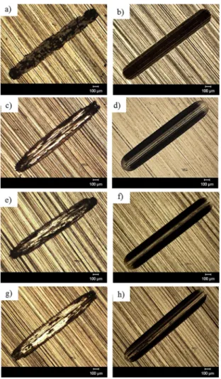
Figure 14 presents optical micrographs of the wear tracks of the samples in dry and medium conditions. Figure 14a shows plastic deformation and debris bed on the track for
the as-received sample. This suggests the predominant
mechanism of plowing28 for this sample; meanwhile, for
the heat-treated steels, the wear mechanism corresponded to cutting. For this reason, the worn volume for the as-received sample is difficult to determine (Figure 9a), and was less
than expected.
Figure 14: Optical microscopy of the worn tracks. a) As Received in
dry condition; b) As Received in corrosive medium; c) Conventional Quenching in dry condition; d) Conventional Quenching in corrosive
medium; e) Cryogenic Treatment (-80 ºC) in dry condition; f) Cryogenic Treatment (-80 ºC) in corrosive medium; g) Cryogenic Treatment (-196 ºC) in dry condition; e h) Cryogenic Treatment (-196 ºC) in corrosive medium.
The presence of a debris bed on the as-received steel
after the wear test (Figure 14a) could be caused by the oxide formation (darkest track on Figure 14a). This sample contains the highest carbide percentage, including chromium carbides. This reduces the amount of chromium available to
form a passive layer. On the other hand, for the same steel condition after the tribocorrosion test, the sodium chloride
medium influenced the wear mechanism, changing from
plowing to cutting.
The corrosion protection mechanism of stainless steels is
based on surface passivation (Figure 8). This is the formation
of a thin, adherent and dense chromium oxide layer on the steel surface3 in air atmosphere. During the wear test, the ball in relative movement removes the chromium oxide layer and exposes the steel to the aggressive environment,
which is confirmed by the decrease of the free potential
values in Figure 15.
Figure 15: Open circuit potential monitoring results before, during
and after wear test.
In the tribocorrosion tests, the sliding velocity is important
because it may influence the repassivation process. When the
ball slides on the surface, more active material is exposed to
the electrolyte; but while the ball removes the passive film,
the chromium oxide layer forms again (repassivation) on the opposite side of the track. This cycle of rupture, corrosion
and regeneration of the passive film brought about the increase in the worn volume (Figure 9). Moreover, wear is
more aggressive in a corrosive medium, although the latter
can also work as a lubricant fluid (Table 8)8. The as-received
steel, which has the lowest hardness, and the sample after
-196 °C cryogenic quenching (the hardest sample), both
show close worn volume values. In order to explain these results, further studies are necessary, because the results obtained here did not allow us to determine the causes of
these different and unexpected behaviors.
Samples of spheroidized steel developed an important potential decrease after the tribocorrosion test (Figure 15). This behavior could be associated with the presence of spheriodized carbides (Figure 3). The carbides are preferential sites for the corrosion process and hamper passivation, as already mentioned.
4. Conclusions
Our results can be summarized as follows:
• The microstructure is dependent on the heat treatment parameters employed. A decrease in the content of
retained austenite was observed, as a function of
the final quenching cooling temperature: 6.12% for conventional quenching, 3.94% for -80 ºC quenching and 3.01% for -196 ºC quenching. These results are
coherent with the Vickers microhardness results. • All the heat-treated samples showed a decrease of
icorr and an increase of pitting potential, compared
to the as-received samples. Consequently, the heat treatments extended the passive region (ΔEpass). The
martensite-rich samples therefore have a better
corrosion resistance than the spheroidized ones. Worn volume is higher for the tribocorrosion tests than for the wear test under dry conditions. • The sample obtained by cryogenic heat treatment
at -196 °C promoted the highest amount of worn
volume under tribocorrosion conditions. The sample
that went through cryogenic heat treatment at -80 °C yielded almost the same worn volume as the conventional heat-treated sample.
5. Acknowledgmentrs
Authors gratefully thank the financial support of the
Brazilian Government Agencies CAPES (Agency for Support and Evaluation of Graduate Education) and CNPq (National
Counsel of Technological and Scientific Development).
6. References
1. Verhoeven JD, Pendray AH, Clark HF. Wear tests of steel knife blades. Wear. 2008;265(7-8):1093-1099.
2. ASM International. ASM Handbook Volume 3: Alloy Phase
Diagrams. Materials Park: ASM International; 1992.
3. Sedriks AJ. Corrosion of stainless steels. 2nd ed. New York: John Wiley and Sons; 1996.
4. Khajavi MR, Shariat MH. Failure of first stage gas turbine
blades. Engineering Failure Analysis. 2004;11(4):589-597. 5. Xi YT, Liu DX, Han D. Improvement of corrosion and wear
resistances of AISI 420 martensitic stainless steel using plasma nitriding at low temperature. Surface and Coatings Technology.
2008;202(12):2577-2583.
6. Li CX, Bell T. Corrosion properties of plasma nitrided AISI 410
martensitic stainless steel in 3.5% NaCl and 1% HCl aqueous solutions. Corrosion Science. 2006;48(8):2036-2049. 7. Lo KH, Shek CH, Lai JKL. Recent developments in stainless
steels. Materials Science and Engineering: R: Reports.
2009;65(4-6):39-104.
8. Berradja A, Bratu F, Benea L, Willems G, Celis JP. Effect of
sliding wear on tribocorrosion behaviour of stainless steels in a Ringer’s solution. Wear. 2006;261(9):987-993.
9. Dodds S, Jones AH, Cater S. Tribological enhancement of AISI 420 martensitic stainless steel through friction-stir processing.
Wear. 2013;302(1-2):863-877.
10. Barron RF. Cryogenic treatment of tool steels. Manufacturing
Strategies. 1996;6:535-548.
11. Molinari A, Pellizzari M, Gialanella S, Straffelini G, Stiasny KH. Effect of deep cryogenic treatment on the mechanical
properties of tool steels. Journal of Materials Processing
Technology. 2001;118(1-3):350-355.
12. Barron RF. Cryogenic treatment of metals to improve wear resistance. Cryogenics. 1982;22(8):409-413.
13. Podgornik B, Majdic F, Leskovsek V, Vizintin J. Improving tribological properties of tool steels through combination
of deep-cryogenic treatment and plasma nitriding. Wear.
2012;288:88-93.
14. Isfahany AN, Saghafian H, Borhani G. The effect of heat
treatment on mechanical properties and corrosion behavior of AISI420 martensitic stainless steel. Journal of Alloys and
Compounds. 2011;509(9):3931-3936.
15. Mathew MT, Runa MJ, Laurent M, Jacobs JJ, Rocha LA Wimmer MA. Tribocorrosion behavior of CoCrMo alloy for hip prosthesis as a function of loads: A comparison between two testing systems. Wear. 2011;271(9-10):1210-1219.
16. ASTM International. ASTM G133-05. Standard Test Method
for Linearly Reciprocating Ball-on-Flat Sliding Wear. West
Conshohocken: ASTM International; 2010.
17. Rhyim YM, Han SH, Na YS, Lee JH. Effect of Deep Cryogenic
Treatment on Carbide Precipitation and Mechanical Properties of Tool Steel. Solid State Phenomena. 2006;118:9-14. 18. Sidoroff C, Perez M, Dierickx P, Girodin D. Advantages
and Shortcomings of Retained Austenite in Bearing Steels: a Review. In: Beswick J. Bearing Steel Technologies: 10th
Volume, Advances in Steel Technologies for Rolling Bearings.
West Conshohocken: ASTM International; 2014. p. 1-37. 19. Barlow LD, Du Toit M. Effect of Austenitizing Heat Treatment
on the Microstructure and Hardness of Martensitic Stainless Steel AISI 420. Journal of Materials Engineering and Performance. 2012;21(7):1327-1336.
20. Roberts G, Kennedy R, Krauss G. Tool Steels. 5th ed. West
Conshohocken: ASM International; 1998.
21. Farina PFS, Farina AB, Barbosa CA, Goldenstein H. Tratamento criogênico e de alívio de tensões em um aço AISI D2. Tecnologia
em Metalurgia, Materiais e Mineração. 2012;9(2):140-147.
22. Hilbert LR, Bagge-Ravn D, Kold J, Gram L. Influence of surface
roughness of stainless steel on microbial adhesion and corrosion resistance. International Biodeterioration & Biodegradation.
2003;52(3):175-185.
23. Sedlaček M, Podgornik B, Vižintin J. Influence of surface
preparation on roughness parameters, friction and wear. Wear.
2009;266(3-4):482-487.
24. Uygur I, Gerengi H, Arslan Y, Kurtay M. The Effects of
Cryogenic Treatment on the Corrosion of AISI D3 Steel.
Materials Research. 2015;18(3):569-574.
25. Frankel GS. Pitting Corrosion of Metals. A Review of the Critical Factors. Journal of The Electrochemical Society.
26. Kimura M, Miyata Y, Toyooka T, Kitahaba Y. Effect of Retained Austenite on Corrosion Performance for Modified 13%Cr Steel
Pipe. Corrosion. 2001;57(3):433-439.
27. Hidalgo PJ. Pitting corrosion of martensitic cutlery steels.
Surface Technology. 1980;10(3):193-208.
28. Ravi N, Markandeya R, Joshi SV. Effect of substrate roughness
on adhesion and tribological properties of nc-TiAlN/a-Si3 N4
nanocomposite coatings deposited by cathodic arc PVD process.
Surface Engineering. 2015;33(1):7-19.
29. Gadelmawla ES, Koura MM, Maksoud TMA, Elewa IM,
Soliman HH. Roughness parameters. Journal of Materials