�������
����������
��������������
In de x In te rfe ro m ete r A cc es so rie s A pp en dix Fil te rs M ou nt s Eta lo ns Po la riz er s Be am sp litt ers U ltr afa st C om po ne nt s M irr or s W av ep lat es Le ns es Pr ism s W in do w s In troPolarizers
Polarization Tutorial . . . 240
Polarizing Beamsplitter Cubes . . . . 243
High Energy Laser Polarizers. . . 247
Polarization Rotators . . . 253
Depolarizers . . . 254
Birefringent Polarizers. . . 255
� � � � ξ Ψ η � � � θ240
Americas (505) 296-9541 | Europe +44 (0) 1624 647000 | Asia +82 (0) 32 673-6114 | Order now at www.cvilaser.com W in do w s Pr is m s Le ns es M irr or s In tr o Be am sp lit te rs Po la ri ze rs W av ep la te s Et al on s Fi lte rs U ltr af as t C om po ne nt s In te rfe ro m et er A cc es so rie s A pp en di x M ou nt s In de xphases of the field components of the left and right circularly polarized components. Note that
3. Elliptical Representation
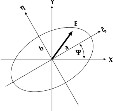
An arbitrary polarization state is generally elliptically polarized. This means that the tip of the electric field vector will describe an ellipse, rotating once per optical cycle. Let a be the semimajor and b be the semiminor axis of the polarization ellipse. Let ψ be the angle that the semimajor axis
makes with the X-axis. Let ξ and η be the axes of a right-handed coordinate system rotated by an angle +ψ with respect to the X-axis and aligned with the polarization ellipse as shown in the diagram below. The elliptical representation is:
Note that the phase shift δo above is required to adjust the time origin, and the parameter ψ is implicit in the rotation of the ξ, η axes with respect to the X, Y axes.
2. Circular Representation
In the circular representation, we resolve the field into circularly polarized components. The basic states are represented by the complex unit vectors
e+ is the unit vector for left circularly polarized light; for positive helicity light; for light that rotates counterclockwise in a fixed plane as viewed facing into the light wave; and for light whose electric field rotation obeys the right hand rule with thumb pointing in the direction of propagation.
e- is the unit vector for right circularly polarized light; for negative helicity light; for light that rotates clockwise in a fixed plane as viewed facing into the light wave; and for light whose electric field rotation disobeys the right hand rule with thumb pointing in the direction of propagation. As in the case of the Cartesian
representation, we write:
where E+ , E-, φ+, and φ- are four real numbers describing the magnitudes and
Technical Notes
Polarization
Figure 1. The polarization ellipse.
� � � � ξ Ψ η � Polarization States
Four numbers are required to describe a single plane wave Fourier component traveling in the +z direction. These can be thought of as the amplitude and phase shift of the field along two orthogonal directions.
1. Cartesian Representation
This is the simplest representation to think about. Ex , Ey, φx, and φy are four real numbers describing the magnitudes and phases of field components along two orthogonal unit vectors x and y. If the origin of time is irrelevant, only the relative phase shift need be specified.
E = (xE
xe
iφx + yE
ye
iφy) e
i(kz-ωt)φ
=
φ
x-
φ
yE = (e
+E
+e
iφ++ e
-E
-e
iφ-) e
i(kz-ωt)E
+= e
-· E
E
-= e
+· E
^ ^E = (aξ + bη)e
iδoe
i(kz-ωt)e
+= (1/
√
2)(x + iy)
e
-= (1/
√
2)(x - iy)
� � � �� �� �Circularly polarized light. Ex and Ey are out of
phase by angular frequency ω.
� � � �� �� �
Linearly polarized light. Ex and Ey are in phase.
Historically, the orientation of a polarized electromagnetic wave has been defined in the optical regime by the orientation of the electric vector. This is the convention that CVI uses.
Americas (505) 296-9541 | Europe +44 (0) 1624 647000 | Asia +82 (0) 32 673-6114 | Order now at www.cvilaser.com
241
In de x In te rfe ro m ete r A cc es so rie s A pp en dix Fil te rs M ou nt s Eta lo ns Po la riz er s Be am sp litt ers U ltr afa st C om po ne nt s M irr or s W av ep lat es Le ns es Pr ism s W in do w s In troA real polarizer has a pass transmission, T||, less than 1. The transmission of the rejected beam, T⊥, may not be 0. If r is a
unit vector along the rejected direction, then
Linear Polarizers
A linear polarizer is a device that creates a linear polarization state from an arbitrary input. It does this by removing the component orthogonal to the selected state. Some polarizers reflect the rejected state, creating a new, usable beam. Examples are the CVI Glan Laser Polarizers, Thin Film Polarizers, and many types of polarizing beamsplitter cubes. Other polarizers, such as Polocor™ and plastic sheet polarizers, absorb the rejected beam which turns into heat. As do polaroid sheet and Polarcor™ polarizers. Still others may refract the two polarized beams at different angles, thereby separating them. Examples are Wollaston and Rochon prism polarizers.
Suppose the pass direction of the polarizer is determined by unit vector p. Then the transmitted field E2, in terms of the incident field E1, is:
where the phase shift of the transmitted field has been ignored.
Technical Notes
Polarization
b. Cartesian to Elliptical Transformation
a. Cartesian to Circular Transformation
a = 1/2 (u + v)
b = 1/2 (-u + v)
ψ = 1/2 (φ
12- φ
34)
δ
o= 1/2 (
φ
12+
φ
34)
E
2= p(p · E
1)
E
2= (T
||)
1/2p(p · E
1)e
iφ||+
(T
⊥)
1/2r(r · E
1)e
iφ⊥T = T
||cos
2θ
+ T
⊥sin
2θ
g
1= E
xcosφ
x- E
ysinφ
yg
2= E
xsin
φ
x+ E
ycos
φ
yg
3= E
xcosφ
x+ E
ysinφ
yg
4= E
xsin
φ
x- E
ycos
φ
yu = +
[
(g
1)
2+ (g
2)
2]
1/2v = +
[
(g
3)
2+ (g
4)
2]
1/2φ
12= atan (g
1, g
2)
φ
34= atan (g
3, g
4)
E
+= v/
√
2
E
-= u/
√
2
φ
+=
φ
34φ
-=
φ
12 ^ ^ To summarize the three representations:Representation Complex Field Amplitude Parameters Specifying Polarization State
Cartesian xExeiφx + yEyeiφy Ex, φx, Ey, φy
Circular e+E+eiφ+ + e-E-eiφ- E+, φ+, E-, φ
-Elliptical (aξ + bη)eiδo a, b, ψ, δo
Conversion Between Representations
For brevity, we will provide only the Cartesian to Circular and Cartesian to Elliptical transformations. The inverse transformations are straightforward. We define the following quantities:
In the above, the phase shifts along the two directions must be retained. Similar expressions could be arrived at for the rejected beam. If θ is the angle between the field E1 and the polarizer pass direction p, the above equation predicts for the transmission:
The above equation shows that when the polarizer is aligned so that θ = 0, T = T||. When it is “crossed”, θ = π/2, and T = T⊥. The extinction ratio is ε = T|| / T⊥. A polarizer with perfect extinction
has T⊥ = 0, and thus T = T|| cos2θ, is a familiar result. Because cos2θ has a broad
maximum as a function of orientation angle, setting a polarizer at a maximum of transmission is generally not very accurate. One has to either map the cos2θ with
sufficient accuracy to find the θ = 0 point, or do a null measurement at θ = ± π/2. In the above, atan(x,y) is the four quadrant
arc tangent function. This means that atan(x,y) = atan(y/x) with the provision that the quadrant of the angle returned by the function is controlled by the signs of both x and y, not just the sign of their quotient; for example, if g2 = g1 = -1, then φ12 above is 5π/4 or -3π/4, not π/4.
242
Americas (505) 296-9541 | Europe +44 (0) 1624 647000 | Asia +82 (0) 32 673-6114 | Order now at www.cvilaser.com W in do w s Pr is m s Le ns es M irr or s In tr o Be am sp lit te rs Po la ri ze rs W av ep la te s Et al on s Fi lte rs U ltr af as t C om po ne nt s In te rfe ro m et er A cc es so rie s A pp en di x M ou nt s In de xSelection Guide
Polarizing Beamsplitter Cubes
�������� ���� ��������� ���� �������������� ����������� ���� ��������������
Dot marks preferred input face. This is the tested direction for transmitted wavefront. Damage threshold is also higher for this orientation as well.
1800 Prism Mounts with 3-Axis adjustment can
Americas (505) 296-9541 | Europe +44 (0) 1624 647000 | Asia +82 (0) 32 673-6114 | Order now at www.cvilaser.com
243
In de x In te rfe ro m ete r A cc es so rie s A pp en dix Fil te rs M ou nt s Eta lo ns Po la riz er s Be am sp litt ers U ltr afa st C om po ne nt s M irr or s W av ep lat es Le ns es Pr ism s W in do w s In troPolarizing Beamsplitter Cubes
Extinction Transmission
Operating Ratio Polarizing Efficiency
Diagram Product Type Conditions (TP/TS) Bandwidth (TP)
Selection Guide
Contacted Polarizing Beamsplitter Cubes PBSOl
250 10J/cm2, 20ns, 20Hz; 200MW/cm2 CW at 1064nm 20nm at 1064nm 95% at 1064nm 200:1 at 1064nm Broadband Polarizing Beamsplitter Cubes PBSKl
252 10J/cm2, 20ns, 20Hz; 1MW/cm2 CW at 1064nm 140nm at 532nm 92% at 800nm 103:1 at 1064nm Harmonic Polarizing Beamsplitter Cubes HPBSl
251 5J/cm2, 20ns, 20Hz; 1MW/cm2 CW at 1064nm for 1064nm, 532nm, 355nm, and 266nm operation 95% at 1064nm 103:1 at 1064nm Polarizing Beamsplitter Cubes PBSl
244 1J/cm2, 20ns, 20Hz at 1064nm 25nm at 515nm 95% 1000:1 UV Polarizing Beamsplitter Cubes UPBSl
245 10mJ/cm2, 20ns, 20Hz; 100W/cm2 CW at 266nm 5nm at 257nm 90% 100:1 Broadband Polarizing Beamsplitter Cubes PBSHl
246 500mJ/cm2, 20ns, 20Hz; 100W/cm2 CW at 515nm > 250nm at 532nm 90% 500:1244
Americas (505) 296-9541 | Europe +44 (0) 1624 647000 | Asia +82 (0) 32 673-6114 | Order now at www.cvilaser.com W in do w s Pr is m s Le ns es M irr or s In tr o Be am sp lit te rs Po la ri ze rs W av ep la te s Et al on s Fi lte rs U ltr af as t C om po ne nt s In te rfe ro m et er A cc es so rie s A pp en di x M ou nt s In de xPBS
Polarizing Beamsplitter Cubes
Polarizing Beamsplitter Cubes
Wavelength 5.0mm 10.0mm 0.50” 1.00” 1.50” 2.00” 488nm PBS-488-020 PBS-488-040 PBS-488-050 PBS-488-100 PBS-488-150 PBS-488-200 500nm PBS-500-020 PBS-500-040 PBS-500-050 PBS-500-100 PBS-500-150 PBS-500-200 515nm PBS-515-020 PBS-515-040 PBS-515-050 PBS-515-100 PBS-515-150 PBS-515-200 532nm PBS-532-020 PBS-532-040 PBS-532-050 PBS-532-100 PBS-532-150 PBS-532-200 633nm PBS-633-020 PBS-633-040 PBS-633-050 PBS-633-100 PBS-633-150 PBS-633-200 670nm PBS-670-020 PBS-670-040 PBS-670-050 PBS-670-100 PBS-670-150 PBS-670-200 780nm PBS-780-020 PBS-780-040 PBS-780-050 PBS-780-100 PBS-780-150 PBS-780-200 800nm PBS-800-020 PBS-800-040 PBS-800-050 PBS-800-100 PBS-800-150 PBS-800-200 810nm PBS-810-020 PBS-810-040 PBS-810-050 PBS-810-100 PBS-810-150 PBS-810-200 830nm PBS-830-020 PBS-830-040 PBS-830-050 PBS-830-100 PBS-830-150 PBS-830-200 850nm PBS-850-020 PBS-850-040 PBS-850-050 PBS-850-100 PBS-850-150 PBS-850-200 930nm PBS-930-020 PBS-930-040 PBS-930-050 PBS-930-100 PBS-930-150 PBS-930-200 1030nm PBS-1030-020 PBS-1030-040 PBS-1030-050 PBS-1030-100 PBS-1030-150 PBS-1030 -200 1047nm PBS-1047-020 PBS-1047-040 PBS-1047-050 PBS-1047-100 PBS-1047-150 PBS-1047-200 1053nm PBS-1053-020 PBS-1053-040 PBS-1053-050 PBS-1053-100 PBS-1053-150 PBS-1053-200 1064nm PBS-1064-020 PBS-1064-040 PBS-1064-050 PBS-1064-100 PBS-1064-150 PBS-1064-200 1319nm PBS-1319-020 PBS-1319-040 PBS-1319-050 PBS-1319-100 PBS-1319-150 PBS-1319-200 1550nm PBS-1550-020 PBS-1550-040 PBS-1550-050 PBS-1550-100 PBS-1550-150 PBS-1550-200 PBS
Projection systems, signal monitoring Color separation and recombination Optical coupling
Fewer ghost images than plate beamsplitters
Optical isolation (In combination with waveplate)
Continuously variable beamsplitter (In combination with waveplate)
Equal optical path lengths 1000:1 extinction ratio
Also called Laser Line Polarizer Cubes Rotary mounts and polarizer adapters available
l
339Polarizing beamsplitter cubes are used to split a laser beam into two orthogonally polarized components; P-polarization is transmitted straight through while S-polarization is reflected at 90º. PBS polarizer cubes utilize a durable all-dielectric coating at the internal cemented interface, and all external surfaces are anti-reflection coated for the wavelength specified. For best spectral performance and transmitted wavefront, cube beamsplitters should be used with collimated or near-collimated input light.
The PBS and other cemented beamsplitter cubes are easy to mount, mechanically durable and ideal for use up to 1J/cm2 at
1064nm. Rotary mounts and adapters for PBS cubes can be found
l
339. For UV wavelengths see product code UPBSl
245. For broadband polarizing cubes, see product code PBSHl
246. For high energy contacted cubes, see product codePBSO
l
250. For non-polarizing cubes, see product code NCBSl
205. For broadband, see PBSH, PBSK and, calcite polarizers.Substrate Material BK7 glass
Dimensional Tolerance ± 0.25mm
Dot marks preferred input face. This is the tested direction for transmitted wavefront. Damage threshold is also higher for this orientation as well.
Extinction Ratio TP / TS > 1000:1 Transmission Efficiency TP > 95%
Reflection Efficiency RS > 99.9%
Antireflection Coating R ≤ 0.25% per surface
Surface Quality 20-10 CVI Laser Quality defined on page 430 Transmitted Wavefront Distortion λ/4 for ≤ 1.00”, λ/2 for > 1.00” at 633nm
Clear Aperture Exceeds central 85% of dimension
Field of View ± 3°
Americas (505) 296-9541 | Europe +44 (0) 1624 647000 | Asia +82 (0) 32 673-6114 | Order now at www.cvilaser.com
245
In de x In te rfe ro m ete r A cc es so rie s A pp en dix Fil te rs M ou nt s Eta lo ns Po la riz er s Be am sp litt ers U ltr afa st C om po ne nt s M irr or s W av ep lat es Le ns es Pr ism s W in do w s In troUPBS
UV Polarizing Beamsplitter Cubes
Fused silica cube polarizers for doubled argon, tripled Nd:YAG, quadrupled Nd:YAG, and UV excimer lasers
100:1 extinction ratio
Transmission efficiency > 90% For use with fluences less than 10mJ/cm2
Contact CVI for 193nm polarizers Rotary mounts and polarizer adapters available
l
339Substrate Material UV grade fused silica
Dimensional Tolerance ± 0.25mm Product Code UPBS Wavelength nm 248 266 351 257 308 355
Size Code Cube Dimension
050 0.50”
100 1.00”
How To Order
UPBS 266 100Polarizing cube beamsplitters divide unpolarized collimated light into two orthogonal polarized beams at 90° to each other. The transmitted beam is polarized parallel to the plane of incidence (p-polarized), and the reflected beam is polarized perpendicular to the plane of incidence. Each beamsplitter consists of a pair of precision high tolerance right angle prisms, which are fixed in relation
to one another by cement. A multi-layer antireflective coating is applied to each face of the beamsplitter to produce maximum transmission efficiency. Laser-line cube beamsplitters are tuned for optimum performance at specific laser wavelengths. These polarizing cube beamsplitters are made from UV grade fused silica to improve UV performance.
UPBS
Dot marks preferred input face. This is the tested direction for transmitted wavefront. Damage threshold is also higher for this orientation as well.
Extinction Ratio TP / TS > 100:1 Transmission Efficiency TP > 90%
Reflection Efficiency RS > 99% Antireflection Coating R ≤ 0.25%
Surface Quality 20-10 CVI Laser Quality defined on page 430 Transmitted Wavefront Distortion λ/4 p-v at 633nm
Clear Aperture Exceeds central 85% of dimension
Field of View ± 2° typical
246
Americas (505) 296-9541 | Europe +44 (0) 1624 647000 | Asia +82 (0) 32 673-6114 | Order now at www.cvilaser.com W in do w s Pr is m s Le ns es M irr or s In tr o Be am sp lit te rs Po la ri ze rs W av ep la te s Et al on s Fi lte rs U ltr af as t C om po ne nt s In te rfe ro m et er A cc es so rie s A pp en di x M ou nt s In de xBroadband polarizing cube optimized for visible and near infrared
500:1 extinction ratio average across full bandwidth
Reflected and transmitted beams separated by 90°
For use with fluences < 500mJ/cm2
PBSH
Broadband Polarizing
Beamsplitter Cubes
Substrate Material SF2 glass
Dimensional Tolerance ± 0.25mm
These polarizing beamsplitter cubes are made from SF2 glass to improve broadband performance. For high energy applications, CVI recommends other materials such as Fused Silica or BK7 though they may not work as well over a wide wavelength range. Polarizing beamsplitter cubes divide unpolarized collimated light into two orthogonal polarized beams at 90° to each other. The transmitted beam is polarized parallel to the plane of incidence (p-polarized), and the reflected beam is polarized perpendicular to the plane of incidence.
Each beamsplitter consists of a pair of precision high tolerance right angle prisms, which are fixed in relation to one another by cement. A multi-layer antireflective coating is applied to each face of the beamsplitter to produce maximum transmission efficiency. Laser-line cube beamsplitters are tuned for optimum performance at specific laser wavelengths.
To avoid damage when using a high power laser, be sure to orient the cube so that the beam enters through the prism marked with the dot.
Broadband Polarizing Beamsplitter Cubes
Wavelength Transmission Antireflection Coating
Part Number Range (nm) Efficiency (TP avg) (Ravg per surface) Cube Size
PBSH-450-700-050 450-700 90% < 0.5% 0.50" PBSH-450-1300-050 450-1300 90% < 2.5% 0.50" PBSH-450-2000-050 450-2000 90% < 3.0% 0.50" PBSH-670-980-050 670-980 90% < 0.5% 0.50" PBSH-1300-1550-050 1300-1550 90% < 0.5% 0.50" PBSH-450-700-100 450-700 90% < 0.5% 1.00" PBSH-450-1300-100 450-1300 90% < 2.5% 1.00" PBSH-450-2000-100 450-2000 90% < 3.0% 1.00" PBSH-670-980-100 670-980 90% < 0.5% 1.00" PBSH-1300-1550-100 1300-1550 90% < 0.5% 1.00" PBSH
Dot marks preferred input face. This is the tested direction for transmitted wavefront. Damage threshold is also higher for this orientation as well.
Surface Quality 40-20 per MIL-PRF-13830B
Transmitted Wavefront Distortion λ/4 p-v at 633nm
Extinction Ratio TP / TS > 500:1 Reflection Efficiency RS > 99.5%
Clear Aperture Exceeds central 85% of dimension
Field of View ± 2.5°
Americas (505) 296-9541 | Europe +44 (0) 1624 647000 | Asia +82 (0) 32 673-6114 | Order now at www.cvilaser.com
247
In de x In te rfe ro m ete r A cc es so rie s A pp en dix Fil te rs M ou nt s Eta lo ns Po la riz er s Be am sp litt ers U ltr afa st C om po ne nt s M irr or s W av ep lat es Le ns es Pr ism s W in do w s In troHigh Energy Laser Polarizers
Extinction Transmission
Operating Ratio Polarizing Efficiency
Diagram Product Type Conditions (TP/TS) Bandwidth (TP)
Selection Guide
Contacted Polarizing Beamsplitter Cubes PBSOl
250 10J/cm2, 20ns, 20Hz; 200MW/cm2 CW at 1064nm 5-10nm at 1064nm 95% at 1064nm 200:1 at 1064nm Broadband Low Dispersion Polarizers TFPKl
249 5J/cm2, 50fsec pulse; 50kW/cm2 CW at 800nm 100nm at 800nm 96% at 800nm 15:1 TP2/TS2 where TP and TSare per surface transmissions ������������ ������������ Depolarizers DPL
l
254 2J/cm2, 20ns, 20Hz; 500kW/cm2 CW at 1064nm 40nm at 1064nm 99% at 1064nm Broadband Polarizing Beamsplitter Cubes PBSKl
252 10J/cm2, 20ns, 20Hz; 1MW/cm2 CW at 1064nm 140nm at 532nm 92% at 800nm 103:1 at 1064nm Harmonic Polarizing Beamsplitter Cubes HPBSl
251 5J/cm2, 20ns, 20Hz; 1MW/cm2 CW at 1064nm for 1064nm, 532nm, 355nm, and 266nm operation 95% at 1064nm 103:1 at 1064nm Thin Film PlatePolarizers TFP
l
248 20J/cm2, 20ns, 20Hz; 1MW/cm2 CW at 1064nm 5nm at 1064nm 95% at 1064nm 200:1 at 1064nm Polarization Rotators RTl
253 10J/cm2, 20ns, 20Hz; 1MW/cm2 CW at 1064nm 10nm at 1064nm �248
Americas (505) 296-9541 | Europe +44 (0) 1624 647000 | Asia +82 (0) 32 673-6114 | Order now at www.cvilaser.com W in do w s Pr is m s Le ns es M irr or s In tr o Be am sp lit te rs Po la ri ze rs W av ep la te s Et al on s Fi lte rs U ltr af as t C om po ne nt s In te rfe ro m et er A cc es so rie s A pp en di x M ou nt s In de xThin Film Plate Polarizers
TFP
High damage threshold polarizer, >20J/cm2
Angle tuning suggested to achieve maximum transmission
Contact CVI for intermediate wavelengths and additional dimensions
Contact a CVI applications engineer for OEM mirror mounts and system integrations capabilities TFP Thin Film Plate Polarizes are the best choice when maximum laser damage resistance is necessary. Typically, TFP
polarizers are used for fluences greater than 500mJ/cm², where calcite air-spaced polarizers exhibit long term tracking and cemented polarizers cannot be used at all. Two typical applications are as intracavity Q-switch hold-off polarizers, and, in conjunction with a half wave plate, as an extracavity attenuator for an Nd:YAG laser fundamental and its harmonics. To maximize transmission, users must make a provision in their mechanical setup for the necessary angular tuning. Note that the losses at the uncoated second surface are insignificant at ±3 degrees from Brewster’s angle. ��������������� ���������������� ��� � �� �� ���� ��� ���� ���� ���� �� �� ���� ���� ���� ����� �����
Transmission vs Wavelength of TFP Series 1064nm Thin Film Plate Polarizer
Substrate Material UV grade fused silica if λ < 425nm BK7 glass if λ is 425nm or above
Surface Figure λ/10 at 633nm before coating
Surface Quality 10-5 CVI Laser Quality defined on page 430 Diameter Tolerance + 0.00mm, - 0.25mm Thickness Tolerance ± 0.25mm Wedge ≤ 5 minutes Chamfer 0.35mm at 45° typical Product Code TFP Center Wavelength nm 248 355 532 1053 266 527 694 1064
Substrate Part Number Dimension Thickness
PW-1025-UV 1.000" 0.250" PW-2025-UV 2.000" 0.250" RW-28.6-14.3-3.2-UV 28.6 x14.3mm 3.2mm PW-1025-C 1.000" 0.250" PW-2025-C 2.000" 0.250" RW-28.6-14.3-3.2-C 28.6 x14.3mm 3.2mm
How To Order
TFP 527 RW-28.6-14.3-3.2-C TFPTransmitted Wavefront Distortion λ/8 p-v at 633nm
Clear Aperture Exceeds central 85% of dimension
Transmission Efficiency 95% for λ ≥ 527nm 90% for 355nm
85% for 248nm and 266nm
TP/TS 200:1 for λ ≥ 527nm
100:1 for 248nm, 266nm, and 355nm
Angle of Incidence 56° ± 3°. Angle tuning is required to achieve reflection and transmission specifications. CVI guarantees these specifications will be met for a single angle between 53° and 59°.
Americas (505) 296-9541 | Europe +44 (0) 1624 647000 | Asia +82 (0) 32 673-6114 | Order now at www.cvilaser.com
249
In de x In te rfe ro m ete r A cc es so rie s A pp en dix Fil te rs M ou nt s Eta lo ns Po la riz er s Be am sp litt ers U ltr afa st C om po ne nt s M irr or s W av ep lat es Le ns es Pr ism s W in do w s In troTFPK
Low Dispersion Polarizers
Ideal for intracavity use in femtosecond regenerative amplifiers
Low group velocity dispersion for ultrashort femtosecond applications
Custom wavelengths from 250 - 1550nm, call for details
(University Science Books, Mill Valley, California, 1986), for a good discussion of linear pulse propagation.
In chirped pulse regenerative
amplification, the pulse may have to pass through one or two polarizers twice per round trip. There can be 10 to 20 round trips before the gain is saturated and the pulse is ejected. At this stage the pulse is long (100ps-1000ps) and the phase shift at each frequency must still be maintained to minimize the recompressed pulse width. The many round trips of the pulse in the regenerative amplifier place stringent requirements on the phase characteristics of the coatings.
Shown are the power transmission curves for S and P polarization and the transmitted phase characteristics of the P component for a TFPK optimized at 800nm. The phase characteristics shown are the group velocity dispersion (GVD) and the cubic phase term. Not shown
are the reflected phase characteristics for S; they are similar to the P transmission curves, also having low nonlinearity and broad bandwidth. Note that both sides of the optic are coated. Therefore, the S and P transmissions per surface should be squared in order to determine the specifications. The phase characteristics show that in all modes of operation, the
TFPK polarizer performance is dominated by the substrate.
There are some subtleties associated with the TFPK. The near 72° angle has to be set properly and optimized. Some thought has to be given to mechanical clearances of the laser beam at such a steep incidence angle. The reflectivity for S is limited to 75%. Variant designs can increase this at a slight loss in bandwidth, increase in incidence angle, and/or increase in insertion loss for the transmitted P component.
������������
������������ Angle of Incidence 72° ± 2°
Wavelength 400nm or 800nm. Custom wavelengths available.
Bandwidth See curve for 800nm performance. Consult CVI for bandwidths at different center wavelengths.
Extinction Ratio TP2/TS2 > 15:1 where TP and TS are per surface transmissions
Reflection Efficiency RS > 75% each surface. S reflectivities of 85% and 95% available at some sacrifice of P transmission. Working angle of incidence will increase. Consult CVI for specifics.
Transmission Efficiency TP > 98% each surface. Slight tilting required to find angle of minimum loss.
Properties for one coated side of a TFPK polarizing beamsplitter optimized for 800nm. Both sides are coated for these properties.
��������������� ��� ��� ��� ��� ��� ��� ��� �� �� �� � ���������������� �� �� �� ��� �� �� �� �� �� �� ���� �� � � �� �� �� ��� �� �� �� �� �� �� �� ���� �� � ���� ���� ���� ���� �� ���� ���� ��� ��� �� ���� ���� �������� �������� ��������
CVI has developed the TFPK Low Dispersion Polarizing Beamsplitters to satisfy requirements for very high power, short pulse lasers. These optics are ideal for intracavity use in femtosecond regenerative amplifiers. The main
emphasis is on linear phase characteristics. See Chapter 9 of Lasers, A. E. Siegman
Product Code
Center Wavelength nm
400 800
Substrate Part Number
l
15-25How To Order
TFPK 800 RW-28.6-14.3-3.2-C250
Americas (505) 296-9541 | Europe +44 (0) 1624 647000 | Asia +82 (0) 32 673-6114 | Order now at www.cvilaser.com W in do w s Pr is m s Le ns es M irr or s In tr o Be am sp lit te rs Po la ri ze rs W av ep la te s Et al on s Fi lte rs U ltr af as t C om po ne nt s In te rfe ro m et er A cc es so rie s A pp en di x M ou nt s In de xHigh Energy Polarizing
Beamsplitter Cubes
PBSO
Substrate Material UV grade fused silica
Dimensional Tolerance ± 0.25mm Product Code PBSO Wavelength nm 248 355 532 257 364 1064 266
Size Code Cube Size
050 0.50”
100 1.00”
How To Order
PBSO 532 050High energy laser line polarizer cube Optically contacted
Reflected and transmitted beams separated by 90°
Contact CVI for other wavelengths from UV to near IR
Rotary mounts and polarizer adapters available
l
339Polarizing cube beamsplitters divide unpolarized collimated light into two orthogonal polarized beams at 90° to each other. The transmitted beam is polarized parallel to the plane of incidence (p-polarized), and the reflected beam is polarized perpendicular to the plane of incidence. Each beamsplitter consists of a pair of precision high tolerance right angle prisms. A multi-layer antireflective coating is applied to each face of the beamsplitter to produce maximum transmission efficiency. Laser-line cube beamsplitters are tuned for optimum performance at specific laser wavelengths.
CVI’s High Energy Polarizing Cube coatings are designed for maximum extinction ratio (Tp/Ts). Those
applications requiring maximum transmission efficiency, Tp > 98.0%
can be achieved by slightly reducing the extinction ratio. Contact a CVI Applications Engineer for more information.
PBSO
Dot marks preferred input face. This is the tested direction for transmitted wavefront. Damage threshold is also higher for this orientation as well.
Extinction Ratio TP/TS > 500:1 for 532nm and 1064nm
250:1 for λ < 500nm
Transmission Efficiency TP > 95%
Reflection Efficiency RS > 99.5% for λ > 500nm
RS > 99.0% for λ < 500nm Transmitted Beam Deviation < 5min
Clear Aperture Exceeds central 85% of dimension
Antireflection Coating R ≤ 0.25%, all entrance and exit surfaces
Surface Quality 20-10 CVI Laser Quality defined on page 430 Transmitted Wavefront Distortion λ/4 p-v at 633nm
Americas (505) 296-9541 | Europe +44 (0) 1624 647000 | Asia +82 (0) 32 673-6114 | Order now at www.cvilaser.com
251
In de x In te rfe ro m ete r A cc es so rie s A pp en dix Fil te rs M ou nt s Eta lo ns Po la riz er s Be am sp litt ers U ltr afa st C om po ne nt s M irr or s W av ep lat es Le ns es Pr ism s W in do w s In troHigh Energy Harmonic Polarizing
Beamsplitter Cubes
HPBS
���� � � �One polarizer for 1064nm, 532nm, 355nm, and 266nm Nd:YAG harmonic wavelengths
Incident and reflected beams separated by 117°
Rotary mounts and polarizer adapters available
l
339Substrate Material Fused silica
Dimensional Tolerance ± 0.25mm
An alternative to calcite and Brewster angle polarizers, the HPBS is an all-in-one solution for systems running multiple Nd:YAG wavelengths along the same beampath. Unlike cemented broadband cube polarizers, the HPBS is optically contacted, coated with all dielectric
materials and manufactured from fused silica material to ensure efficient transmission at the UV wavelength harmonics. The near cube design is also easy to mount; rotary mounts and adapters are available on page 339.
High Energy Harmonic Polarizing Beamsplitter Cubes
Wavelengths Size 1064nm 532nm 355nm 266nm
Part Number (nm) X by Y (in) TP TP/TS TP TP/TS TP TP/TS TP TP/TS
HPBS-266/355/532/1064-050 266/355/532/1064 0.500 x 0.688 95% 103:1 92% 103:1 85% 103:1 80% 500:1
HPBS-266/355/532/1064-100 266/355/532/1064 1.000 x 1.375 95% 103:1 92% 103:1 85% 103:1 80% 500:1
HPBS
Dot marks preferred input face. This is the tested direction for transmitted wavefront. Damage threshold is also higher for this orientation as well.
Clear Aperture Exceeds central 85% of dimension
Surface Quality 20-10 CVI Laser Quality defined on page 430 Transmitted Wavefront Distortion λ/4 at 633nm
Damage Threshold 5J/cm2, 20ns, 20Hz; 1MW/cm2 CW at 1064nm
1800 Prism Mounts with 3-Axis adjustment can
252
Americas (505) 296-9541 | Europe +44 (0) 1624 647000 | Asia +82 (0) 32 673-6114 | Order now at www.cvilaser.com W in do w s Pr is m s Le ns es M irr or s In tr o Be am sp lit te rs Po la ri ze rs W av ep la te s Et al on s Fi lte rs U ltr af as t C om po ne nt s In te rfe ro m et er A cc es so rie s A pp en di x M ou nt s In de xHigh Energy Broadband
Polarizing Beamsplitter Cubes
PBSK
����
� �
�
λ/4 reflected and transmitted wavefront distortion
Damage threshold up to 10J/cm2 at 1064nm
Incidence and reflected beams separated by 117°
Contact CVI for other designs between 230nm and 2100nm
Rotary mounts and polarizer adapters available
l
3393-Axis control prism mount
l
380Substrate Material Fused silica
Dimensional Tolerance ± 0.25mm
An alternative to calcite and Brewster angle polarizers, the PBSK is an optimal solution for high energy broadband or multi-line systems. Unlike cemented cube polarizers, the PBSK is optically contacted, coated with all dielectric materials and
manufactured from fused silica to ensure high transmission and high damage threshold. The near-cube design is easy to mount; rotary mounts and adapters are available
l
339.High Energy Broadband Polarizing Beamsplitter Cubes
Wavelength Cube Dimension Transmission Extinction
Part Number Range (nm) X by Y (in) Efficiency (TP) Ratio
PBSK-248-308-050 248-308 0.500 x 0688 85% 103:1 PBSK-248-308-100 248-308 1.000 x 1.375 85% 103:1 PBSK-460-600-050 460-600 0.500 x 0688 92% 103:1 PBSK-460-600-100 460-600 1.000 x 1.375 92% 103:1 PBSK-700-900-050 700-900 0.500 x 0688 92% 103:1 PBSK-700-900-100 700-900 1.000 x 1.375 92% 103:1 PBSK-950-1230-050 950-1230 0.500 x 0688 92% 103:1 PBSK-950-1230-100 950-1230 1.000 x 1.375 92% 103:1 PBSK
Dot marks preferred input face. This is the tested direction for transmitted wavefront. Damage threshold is also higher for this orientation as well.
Clear Aperture Exceeds central 85% of dimension
Antireflection Coating Ravg≤ 0.50% per surface
Surface Quality 20-10 CVI Laser Quality defined on page 430 Transmitted Wavefront Distortion λ/4 p-v at 633nm
Americas (505) 296-9541 | Europe +44 (0) 1624 647000 | Asia +82 (0) 32 673-6114 | Order now at www.cvilaser.com
253
In de x In te rfe ro m ete r A cc es so rie s A pp en dix Fil te rs M ou nt s Eta lo ns Po la riz er s Be am sp litt ers U ltr afa st C om po ne nt s M irr or s W av ep lat es Le ns es Pr ism s W in do w s In troPolarization Rotators
RT
� Alignment-insensitive single wavelength rotatorBased on optical activity of crystal quartz
Other wavelengths and sizes are readily available
These rotators have the outstanding feature that their alignment is not a function of their rotation. They are simply placed in the beam at normal incidence. CVI has a range of standard wavelength 45° and 90° rotators and can quickly fabricate rotators at user
specified wavelengths. Crystalline quartz rotators based on circular birefringence are very convenient high damage threshold devices. They are useful over a narrow band of wavelengths centered at the design wavelength.
Substrate Material Crystal quartz
Surface Quality 10-5 CVI Laser Quality defined on page 430 Diameter Tolerance + 0.00mm, - 0. 25mm
Parallelism ≤ 0.5 arc seconds
Rotation Tolerance ±0.50º of rotation
Crystal Quartz Polarization Rotators
Wavelength Diameter Part Number Trans. Wavefront Part Number Trans. Wavefront
(nm) D 45° p-v @ 633nm 90° p-v @ 633nm 248 1.000" RT-10-248-45 λ/10 RT-10-248-90 λ/10 266 1.000" RT-10-266-45 λ/10 RT-10-266-90 λ/10 355 1.000" RT-10-355-45 λ/10 RT-10-355-90 λ/10 527 1.000" RT-10-527-45 λ/10 RT-10-527-90 λ/10 532 1.000" RT-10-532-45 λ/10 RT-10-532-90 λ/10 633 1.000" RT-10-633-45 λ/10 RT-10-633-90 λ/10 755 1.000" RT-10-755-45 λ/10 RT-10-755-90 λ/10 800 1.000" RT-10-800-45 λ/10 RT-10-800-90 λ/10 850 1.000" RT-10-850-45 λ/10 RT-10-850-90 λ/10 1030 1.000" RT-10-1030-45 λ/10 RT-10-1030-90 λ/10 1053 1.000" RT-10-1053-45 λ/10 RT-10-1053-90 λ/6 1064 1.000" RT-10-1064-45 λ/10 RT-10-1064-90 λ/6 RT
Clear Aperture Exceeds central 85% of dimension
Antireflection Coating R ≤ 0.25%, per surface
Transmitted Wavefront see table
254
Americas (505) 296-9541 | Europe +44 (0) 1624 647000 | Asia +82 (0) 32 673-6114 | Order now at www.cvilaser.com W in do w s Pr is m s Le ns es M irr or s In tr o Be am sp lit te rs Po la ri ze rs W av ep la te s Et al on s Fi lte rs U ltr af as t C om po ne nt s In te rfe ro m et er A cc es so rie s A pp en di x M ou nt s In de x Raman amplificationOptically contacted fused silica and crystal quartz wedges
Broadband antireflection coatings applied to input and output faces
Eliminates systematic errors using polarization sensitive optics in detection systems
Other sizes and wavelength ranges are available
Substrate Material Fused silica and crystal quartz
Surface Quality Polished surfaces
10-5 CVI Laser Quality defined on page 430 Retardation Change 0.5 λ/mm at 1064nm
Diameter Tolerance + 0.00mm, - 0.25mm
The DPL depolarizer consists of optically contacted 3° wedges of crystal quartz and fused silica. This inherently high damage threshold optic operates by imparting a variable phase shift across the beam aperture. At 488nm, this phase variation is 1 wave per millimeter. Thus by using an aperture of several millimeters, even
a perfectly polarized monochromatic beam can be effectively depolarized. Other sizes and wavelength ranges are available. Depolarizers are often used in Raman amplification, as the Raman scattering effect is highly dependent upon polarization. Depolarization is also used in some instrumentation applications.
DPL
Depolarizers
Depolarizers
Diameter Wavelength Range of
Part Number (in) AR Coating (nm)
DPL-10-450-700 1.00 450-700
DPL-10-650-1100 1.00 650-1100
DPL-10-1200-1550 1.00 1200-1550
DPL
Clear Aperture Exceeds central 85% of dimension
Antireflection Coating Ravg≤ 0.50% per surface Transmitted Wavefront Distortion λ/4 p-v at 633nm
Americas (505) 296-9541 | Europe +44 (0) 1624 647000 | Asia +82 (0) 32 673-6114 | Order now at www.cvilaser.com
255
In de x In te rfe ro m ete r A cc es so rie s A pp en dix Fil te rs M ou nt s Eta lo ns Po la riz er s Be am sp litt ers U ltr afa st C om po ne nt s M irr or s W av ep lat es Le ns es Pr ism s W in do w s In troBirefringent Polarizers
ExtinctionOperating Ratio Polarizing Transmission
Diagram Product Type Conditions (TP/TS) Bandwidth Efficiency
Selection Guide
Glan Brewster Angle Air-Spaced Polarizers CPBA
l
256 1J/cm2, 20ns, 20Hz; 500W/cm2, CW at 1064nm typical 400-2300nm 99% TP 5 x 10⁴:1 Glan Laser Linear Polarizers CLPAl
257 100mJ/cm2, 20ns, 20Hz; 100W/cm2, CW at 1064nm typical 400-2300nm 95% TP 5 x 10⁵:1Glan Laser Single Escape Window Polarizers CPAS
l
257 500mJ/cm2, 20ns, 20Hz; 500W/cm2, CW at 1064nm typical 400-2300nm 95% TP 5 x 10⁵:1Glan Laser Double Escape Window Polarizers CPAD
l
257 500mJ/cm2, 20ns, 20Hz; 500W/cm2, CW at 1064nm typical 400-2300nm 95% TP 5 x 10⁵:1 Glan Thompson Linear Polarizers CLPGl
258 10mJ/cm2, 20ns, 20Hz; 10W/cm2, CW at 1064nm typical 400-2300nm 95% TS 5 x 10⁵:1 Glan Thompson Polarizing Beamsplitters CPBSl
259 10mJ/cm2, 20ns, 20Hz; 10W/cm2, CW at 1064nm typical 350-2200nm 95% TS 90%TP 105:1 Rochon Prism Polarizers RCHPl
260 10mJ/cm2, 20ns, 20Hz; 10W/cm2, CW at 1064nm typical 150-8000nm 95% TS and TP 105:1 Wollaston Prism Polarizers WLSTl
261 10mJ/cm2, 20ns, 20Hz; 10W/cm2, CW at 1064nm typical 300-2200nm 95% TS and TP 105:1 ������������ ������������ ������������ ������������256
Americas (505) 296-9541 | Europe +44 (0) 1624 647000 | Asia +82 (0) 32 673-6114 | Order now at www.cvilaser.com W in do w s Pr is m s Le ns es M irr or s In tr o Be am sp lit te rs Po la ri ze rs W av ep la te s Et al on s Fi lte rs U ltr af as t C om po ne nt s In te rfe ro m et er A cc es so rie s A pp en di x M ou nt s In de xGlan Brewster Angle
Air-Spaced Polarizers
Brewster angle incidence at all surfaces yields greater than 98% transmission efficiency
Rejected beams available for beamsplitting/beam combining applications or safe dumping
No antireflection coatings needed Rotary mounts and polarizer adapters available
l
339 ����������� ����������� � � �Glan Laser type prisms of the CLPA,
CPAS, and CPAD Series suffer a small, unavoidable loss at the two internal calcite-air interfaces. This loss is avoided in the CPBA Series polarizers by presenting the P polarized transmitted beam to these interfaces at Brewster's angle. The result is a high power, low loss polarizer that does not need AR
coating. The user should be aware of two important considerations in the use of
CPBA polarizers. First, stringent angular acceptance requirements dictate use with collimated beams only. Second, the transmitted beam has a relatively large parallel beam displacement with respect to the incident beam.
Substrate Material Calcite
Transmitted Wavefront Distortion λ/4 p-v at 633nm
Surface Quality 40-20 per MIL-PRF-13830B
Extinction Ratio 5 x 10⁴:1 Transmission Efficiency TP > 98%
Damage Threshold 1J/cm2, 20ns, 20Hz; 500W/cm2 CW at 1064nm
CPBA
Glan Brewster Angle Air-Spaced Polarizers
Clear Dimension Beam
Part Number Aperture W by H Displacement (D)
CPBA-5.0 5.0mm 15.7mm x 15.7mm 5.0mm
CPBA-10.0 10.0mm 25.4mm x 38.1mm 10.0mm
Americas (505) 296-9541 | Europe +44 (0) 1624 647000 | Asia +82 (0) 32 673-6114 | Order now at www.cvilaser.com
257
In de x In te rfe ro m ete r A cc es so rie s A pp en dix Fil te rs M ou nt s Eta lo ns Po la riz er s Be am sp litt ers U ltr afa st C om po ne nt s M irr or s W av ep lat es Le ns es Pr ism s W in do w s In troGlan Laser Polarizers
CLPA CPAS CPAD
Substrate Material Calcite
Transmitted Wavefront Distortion λ/4 p-v at 633nm
Surface Quality 40-20 per MIL-PRF-13830B
Extinction Ratio 5 x 10⁵:1 Transmission Efficiency TP > 95%
Antireflection Coating Ravg≤ 0.50% Damage Threshold see tables
� �
Glan Laser Linear Polarizers
AR Coating AR Coating Diameter Length CA Damage
425-675nm 670-1064nm D (mm) L (mm) Ø (mm) Threshold CLPA-8.0-425-675 CLPA-8.0-670-1064 19.0 19.1 8.0 100mJ/cm2 CLPA-10.0-425-675 CLPA-10.0-670-1064 22.2 22.3 10.0 100mJ/cm2 CLPA-12.0-425-675 CLPA-12.0-670-1064 25.4 25.4 12.0 100mJ/cm2 CLPA-15.0-425-675 CLPA-15.0-670-1064 31.7 30.2 15.0 100mJ/cm2 CLPA-17.0-425-675 CLPA-17.0-670-1064 34.9 34.9 17.0 100mJ/cm2 CLPA-20.0-425-675 CLPA-20.0-670-1064 38.0 38.1 20.0 100mJ/cm2 The Glan Laser prism polarizer is made of
two calcite prisms which are assembled with an air space. This polarizer is a modification of the Glan Taylor type and is designed to have less reflection loss at the prism junction. This polarizer is available with zero, one or two escape windows. The escape windows allow the rejected ordinary beam to escape out of the
polarizer which makes it more desirable for high energy lasers. The polished faces on the exit window sides are in the fragile cleavage plane of the calcite. Therefore, the surface quality of these faces is relatively poor as compared to that of entrance and exit faces. No scratch dig surface quality specifications are assigned to these faces.
Broadband medium power polarizers BBAR coated for visible or
near IR wavelengths Double escape window for intracavity use
105:1 extinction ratio calcite polarizer
Glan Laser Single Escape Window Polarizers
AR Coating AR Coating Dimension Dimension CA Damage
425-675nm 670-1064nm A (mm) B (mm) Ø (mm) Threshold CPAS-8.0-425-675 CPAS-8.0-670-1064 19.0 19.1 8.0 >500mJ/cm2 CPAS-10.0-425-675 CPAS-10.0-670-1064 22.1 22.2 10.0 >500mJ/cm2 CPAS-12.0-425-675 CPAS-12.0-670-1064 25.3 25.4 12.0 >500mJ/cm2 CPAS-15.0-425-675 CPAS-15.0-670-1064 31.7 30.2 15.0 >500mJ/cm2 CPAS-17.0-425-675 CPAS-17.0-670-1064 34.8 34.9 17.0 >500mJ/cm2 CPAS-20.0-425-675 CPAS-20.0-670-1064 38.0 38.1 20.0 >500mJ/cm2 � � � ���
Glan Laser Double Escape Window Polarizers
AR Coating AR Coating Dimension Dimension CA Damage
425-675nm 670-1064nm A (mm) B (mm) Ø (mm) Threshold CPAD-8.0-425-675 CPAD-8.0-670-1064 19.0 19.1 8.0 500mJ/cm2 CPAD-10.0-425-675 CPAD-10.0-670-1064 22.1 22.2 10.0 500mJ/cm2 CPAD-12.0-425-675 CPAD-12.0-670-1064 25.3 25.4 12.0 500mJ/cm2 CPAD-15.0-425-675 CPAD-15.0-670-1064 32.4 30.2 15.0 500mJ/cm2 CPAD-17.0-425-675 CPAD-17.0-670-1064 34.8 34.9 17.0 500mJ/cm2 CPAD-20.0-425-675 CPAD-20.0-670-1064 38.0 38.1 20.0 500mJ/cm2 � � � ������������ ������������ ��� ��� ������������ ������������ CPADCPAS CLPA
258
Americas (505) 296-9541 | Europe +44 (0) 1624 647000 | Asia +82 (0) 32 673-6114 | Order now at www.cvilaser.com W in do w s Pr is m s Le ns es M irr or s In tr o Be am sp lit te rs Po la ri ze rs W av ep la te s Et al on s Fi lte rs U ltr af as t C om po ne nt s In te rfe ro m et er A cc es so rie s A pp en di x M ou nt s In de xGlan Thompson Linear Polarizers
CLPG
Fluorescence polarization Broadband low power polarizers BBAR coated for visible or near IR wavelengths
Acceptance angle ± 7° about normal Rotary mounts and polarizer adapters available
l
339Substrate Material Calcite
Transmitted Wavefront Distortion λ/4 p-v at 633nm
Extinction Ratio 5 x 10⁵:1 Transmission Efficiency TP > 95%
Antireflection Coating Ravg≤ 0.50%
Housing Material Black anodized aluminum
Damage Threshold 10mJ/cm2 , 20ns, 20Hz; 10W/cm2 CW at 1064n
Glan Thompson Linear Polarizers
AR Coating AR Coating Diameter Length Clear Aperture
425-675nm 670-1064nm D (mm) L (mm) Diameter (mm) CLPG-8.0-425-675 CLPG-8.0-670-1064 19.0 28.6 8.0 CLPG-10.0-425-675 CLPG-10.0-670-1064 22.2 34.9 10.0 CLPG-12.0-425-675 CLPG-12.0-670-1064 25.3 38.1 12.0 CLPG-14.0-425-675 CLPG-14.0-670-1064 28.5 47.6 14.0 CLPG-16.0-425-675 CLPG-16.0-670-1064 34.9 54.0 16.0 CLPG-20.0-425-675 CLPG-20.0-670-1064 41.2 60.3 20.0 � � CLPG
Glan Thompson polarizers are used in fluorescence polarization, for optimizing specular reflection spectroscopy
measurements and to remove interference fringes from transmission spectra recorded at Brewster’s angle.
Glan Thompson polarizers have a large acceptance angle while maintaining a high extinction of the P polarization component. In applications where both polarizations are required, use a CPBS
Glan Thompson polarizing beamsplitter, see page 259.
Americas (505) 296-9541 | Europe +44 (0) 1624 647000 | Asia +82 (0) 32 673-6114 | Order now at www.cvilaser.com
259
In de x In te rfe ro m ete r A cc es so rie s A pp en dix Fil te rs M ou nt s Eta lo ns Po la riz er s Be am sp litt ers U ltr afa st C om po ne nt s M irr or s W av ep lat es Le ns es Pr ism s W in do w s In troGlan Thompson Polarizing
Beamsplitters
CPBS
Fluorescence polarization Broadband low power polarizing beamsplitter
BBAR coated for visible or near IR wavelengths
Reflected beam deviated by 45° is always normal to exit surface and does not change angle with wavelength
Rotary mounts and polarizer adapters available
l
339Substrate Material Calcite
Transmitted Wavefront Distortion λ/4 p-v at 633nm
Extinction Ratio TS 1 x 10⁵:1; TP 5 x 10⁻⁵:1 Transmission Efficiency TS > 95%; TP > 90%
Deviation Angle θ 45°
Antireflection Coating Ravg≤ 0.50%
Housing Material Black anodized aluminum
Damage Threshold 10mJ/cm2 , 20ns, 20Hz; 10W/cm2 CW at 1064nm
Glan Thompson Polarizing Beamsplitters
AR Coating AR Coating Length Height Width Clear Aperture
425-675nm 670-1064nm A (mm) B (mm) C (mm) Diameter (mm) CPBS-8.0-425-675 CPBS-8.0-670-1064 28.6 22.2 15.8 8.0 CPBS-10.0-425-675 CPBS-10.0-670-1064 34.9 25.4 22.1 10.0 CPBS-12.0-425-675 CPBS-12.0-670-1064 38.1 28.6 25.3 12.0 � � θ � CPBS
Glan Thompson polarizers are used in fluorescence polarization, for optimizing specular reflection spectroscopy
measurements and to remove interference fringes from transmission spectra recorded at Brewster’s angle.
Glan Thompson polarizers have a large acceptance angle while maintaining a high extinction of the P polarization component. In applications where both polarizations are required, for example dual-channel detection, it is typical to use a CPBS Glan Thompson polarizing beamsplitter.
260
Americas (505) 296-9541 | Europe +44 (0) 1624 647000 | Asia +82 (0) 32 673-6114 | Order now at www.cvilaser.com W in do w s Pr is m s Le ns es M irr or s In tr o Be am sp lit te rs Po la ri ze rs W av ep la te s Et al on s Fi lte rs U ltr af as t C om po ne nt s In te rfe ro m et er A cc es so rie s A pp en di x M ou nt s In de xRochon Prism Polarizers
RCHP
VUV grade MgF2 or calcite polarizers
MgF2 deviation angle 5.1° at 193nm
S polarized (extraordinary) beam deviations of 5°, 10°, and 15° available
Broadband 105:1 extinction ratio
MgF2 polarizing bandwidth:
150-8000nm
Substrate Material MgF2 or Calcite/FK5 glass Transmitted Wavefront Distortion λ/4 p-v at 633nm
Surface Quality 40-20 per MIL-PRF-13830B
Extinction Ratio 1 x 10³:1 - MgF2
1 x 10⁵:1 - calcite Transmission Efficiency T > 95%
Field of View 3° about normal
Antireflection Coating Ravg≤ 0.50% Outside Diamter D 19.0mm
Clear Aperture 10.0mm
Damage Threshold Calcite
10mJ/cm2, 20ns, 20Hz; 10W/cm2 CW at 1064nm
MgF2
100mJ/cm2, 20ns, 20Hz; 10W/cm2 CW at 1064nm
MgF
2Rochon Prism Polarizers
Deviation Diameter Length Clear Aperture Wavelength Range
Part Number Angle (°) D (mm) L (mm) Diameter (mm) of AR Coating (nm)
RCHP-5.0-MF 5.0 at 248nm 38.1 57.2 9.0 uncoated
Calcite Rochon Prism Polarizers
AR Coating AR Coating Deviation Length
Uncoated 425-675nm 670-1064nm Angle (°) L (mm)
RCHP-5.0-CA RCHP-5.0-CA-425-675 RCHP-5.0-CA-670-1064 5.0 19.1 RCHP-10.0-CA RCHP-10.0-CA-425-675 RCHP-10.0-CA-670-1064 10.0 19.1 RCHP-15.0-CA RCHP-15.0-CA-425-675 RCHP-15.0-CA-670-1064 15.0 28.6
�
� θ
RCHP
Rochon prisms are used in applications where good polarization selectivity is required across a large range of wavelengths. In a Rochon prism, both polarization components are transmitted. The P component is transmitted directly through and the S component is deviated from the normal. Calcite RCHP has an extinction ratio of 1 x 10⁵:1 from 450nm
to 2300nm. For a larger wavelength range requirement or deep UV performance, MgF2RCHP can be used with an extinction ratio of 1 x 10³:1 from 140nm
to 6000nm.
MgF2RCHP comprise two prisms of single crystal magnesium fluoride which are optically contacted. Calcite RCHP comprise a prism of calcite and a prism of FK5 glass cemented together. In a Rochon, one prism must have its optical axis perpendicular to the entrance polished face; in calcite this is a fragile plane. Therefore, FK5 has been chosen as a more robust material with similar optical properties as calcite.
Americas (505) 296-9541 | Europe +44 (0) 1624 647000 | Asia +82 (0) 32 673-6114 | Order now at www.cvilaser.com
261
In de x In te rfe ro m ete r A cc es so rie s A pp en dix Fil te rs M ou nt s Eta lo ns Po la riz er s Be am sp litt ers U ltr afa st C om po ne nt s M irr or s W av ep lat es Le ns es Pr ism s W in do w s In troWollaston Prism Polarizers
WLST
Calcite polarizers available with and without BBAR coatings
Beam separation of 5°, 10°, 15°, and 20° available
Broadband 105:1 extinction ratio
Calcite polarizing bandwidth: 300-2200nm
Substrate Material Calcite
Transmitted Wavefront Distortion λ/4 p-v at 633nm
Surface Quality 40-20 per MIL-PRF-13830B
Extinction Ratio 1 x 10⁵:1 Transmission Efficiency T > 95%
Antireflection Coating Ravg≤ 0.50% Outside Diamter D 19.0mm
Clear Aperture 10.0mm
Damage Threshold 10mJ/cm2, 20ns, 20Hz; 10W/cm2 CW at 1064nm
Wollaston Prism Polarizers
AR Coating AR Coating Separation Angle (°) Length
Uncoated 425-675nm 670-1064nm θ1 + θ2 L (mm)
WLST-5.0-CA WLST-5.0-CA-425-675 WLST-5.0-CA-670-1064 5.0 15.9 WLST-10.0-CA WLST-10.0-CA-425-675 WLST-10.0-CA-670-1064 10.0 15.9 WLST-15.0-CA WLST-15.0-CA-425-675 WLST-15.0-CA-670-1064 15.0 19.1 WLST-20.0-CA WLST-20.0-CA-425-675 WLST-20.0-CA-670-1064 20.0 19.1
�
θ
�WLST
The WLST Calcite Wollaston prism polarizer comprises two prisms of calcite cemented together. The ordinary ray in the first half of the prism becomes the extraordinary ray in the second half, and vice versa. Therefore, the two output beams in a Wollaston polarizer exit with a beam deviation from normal (see table below).