Performance Analysis of Solar Air Heater Using CFD
Sanket Khamitkar
1*,Dr. O. D. Hebbal
2*1*
PG Student, Thermal Power Engineering, PDA College of Engineering, Gulbarga-585102,
Karnataka (INDIA)
2*
Professor, Department of Mechanical Engineering, PDA College of Engineering,
Gulbarga-585102, Karnataka (INDIA)
Abstract
In this paper, the thermal efficiency of a solar air collector called unglazed transpired collector (UTC) has been studied using CFD. Experimental results were validated. The study was done to calculate efficiency of solar air heater under hot climatic conditions with two different mass flow rates of air. A commercial finite volume software (CFX) was used to model the heat transfer through the UTC. It was found that temperature rise decreases with increasing air mass flow rate and the efficiency increases with increasing air mass flow rate. Increasing the irradiation level seems to have a very limited effect on the collector efficiency for both mass flow rates. Still, the results show a small increase in efficiency as the irradiation intensity decreases for both mass flow rates.
Keywords: CFD, unglazed transpired solar air collector, thermal performance
1. Introduction
Energy consumption is on increase and the fossil fuels cannot last forever. Extensive fossil fuel consumption by human beings has led to some undesirable phenomena such as atmospheric and environmental pollutions. Consequently, global warming, greenhouse effect, climate change, ozone layer depletion and acid rain terminologies started to appear in the literature frequently. So, it has become the need of an hour to use the energy resource which is clean and eco friendly. Solar energy is one of the better options for clean energy. Solar air heating is a heating technology used to heat or condition air for buildings or process heat applications. It is typically the most cost-effective out of all the solar technologies, especially in commercial and industrial applications, and it addresses the largest usage of building energy in heating climates, which is space heating and industrial process heating.
Solar air collectors can be commonly divided into two categories:
Unglazed Air Collectors or Transpired Solar Collector
Glazed Solar Collectors
In this study we are going to focus on Unglazed Transpired Collectors. Unglazed transpired collectors (UTC’s) are now a well-recognized solar air heater for heating outside air directly. They are key components in many engineering applications, such as in institutional and residential heating, industrial processes like sewage wastewater treatment, and food processing, crop drying. They differ from conventional solar air collectors in that their external wall is replaced by a black perforated sheet, that is unglazed, that allows the collection of solar irradiation.
After studying number of papers related with solar air heater it was observed that very less work has been carried out to study the performance of the device under hot climatic conditions like India. In this work the performance will be studied with CFD software in hot climatic conditions. Also the effect of different parameters such as air flow rate, ambient temperature, solar radiation intensity on the performance of the solar air heater system will be studied.
2. Principle of working
Figure.1 Basic principle of working of solar air heater The basic principle of working of an Unglazed Transpired Solar Collector is as shown in figure 1.The unglazed transpired collector (UTC) has a dark
IJERT
IJERT
perforated surface through which air is drawn. Unlike typical solar air heaters, the UTC does not have a layer of glazing covering its front, and, unlike matrix collectors, it uses a single thin perforated sheet instead of a thick matrix for the solar absorber. The collector is typically mounted on the south side of the exterior of a building. Figure1 shows irradiation heating the absorber surface through which air is heated as it is swept across the surface to the holes. The warmed air then moves up the plenum and is delivered to the building interior by a fan. A fan is necessary to overcome the pressure drop across the collector to drive the air through the absorber. The absorber surface is most commonly a thin perforated aluminum sheet, although other materials have been used such as fabric. The porosity of the collector surface is typically 0.5 to 2%. The space behind the absorber is called plenum. Figure1 shows a cross-section of an unglazed transpired collector and building. The depth of the plenum varies from one collector design to another. Typical depths are between 5 and 30 cm. The back wall of the plenum is commonly the building's exterior surface.
After sunrise, as the radiant intensity increases, the temperature of the absorber increases, then the air in the plenum is heated by the absorber, when the air temperature reaches the set point, the temperature controller starts the blowing fan and forms negative pressure in the plenum, so outside air is sucked into the plenum and heated during the passage of air through the plenum, then hot air is delivered by air pipes to the place where heat is needed.
The efficiency of solar air heater can be calculated by using the equation 1
= (m*Cp* ΔT)/ (I*A) (1)
=Efficiency
m=mass flow rate of air (Kg/s)
Cp=Specific heat of air at constant pressure (KJ/Kgk)
ΔT=Difference between inlet and outlet temperatures of solar air heater (ºC)
I=Solar radiation intensity (W/m²) A=Area of collector plate (m²)
3. Solar air heater model specifications
The solar air heater mainly consists of UTC (Unglazed Transpired Collector) plate, plenum space and a suction duct at the back of the collector plate. We selected the different parameters of device as specified in paper Experimental study of solar air heating system based on unglazed transpired collector ,Proceedings of the ASME 2011 5th International Conference on Energy Sustainability ES2011 August 7-10, 2011, Washington, DC, USA by Lixin Gao ,Hua Bai, Xiumu Fang. The unglazed transpired collector is constructed from metal plate, which is perforated and covered with selective coating. The collector is mounted out 150 mm from the south exterior wall of a building to form an air cavity (also termed plenum).
The structure of UTC-based solar air heating system is shown in figure 2 and the system consists of two systems, that is, solar energy collecting sub-system and heated air delivering sub-sub-system. The solar energy collecting sub-system with an area of 2.5 m² was used for experiments. We also used the device with same dimensions for validation of the experimental results and CFD results.
Figure .2 Actual model of solar air heater
IJERT
IJERT
4. Governing Equations
The governing equations of fluid flow represent mathematical statements of conservation laws of physics. These are the equations which must be solved subject to the boundary conditions of respective problems to get the solution of that problem.
Continuity equation Momentum equations
Energy equation
5. Modeling and meshing
Modeling includes the generation of the geometry as per specifications as specified below
• Collector Area – 2.5 m²
• Plenum Length – 150 mm
• Collector Plate Dimensions- 2.00x1.25 m
• Perforation Diameter- 18 mm
• Number of perforations -50
• Perforations area- 2%
The AutoCAD 2008 was used for creation of the model of solar air heater. Ansys ICEM CFD (version 13.0) was used for the meshing. Ansys CFX was used as a solver.
5.1 Plate geometry
Figure.3Collector plate geometry
The collector plate construction is as shown in figure 3. The area of the plate is 2.5m².The length of plate is 2m and breadth is 1.25m.The thickness of the plate is taken as 5mm.The perforations on the plate are 2% that is the 2% area out of total area is perforated. Basically the hole diameter is between the range of 1.5-2.5mm.But we have selected diameter as 18mm because if we had selected the diameter as 2-2.5mm the total numbers of holes required becomes almost equal to 2500.It becomes quite difficult to create a model with so much number of holes. And for such models mesh size should be very much small which leads to such a high number of elements which requires high capacity computers. To overcome this problem we have selected the large hole diameter keeping the total percentage of perforated area constant that is equal to 2% of the total area.
5. Boundary conditions
The collector plate The boundary conditions mainly include solar radiation intensity, ambient temperature, mass flow rate of air at inlet and at outlet .As there is suction created by the suction fan at outlet the mass flow rate of air at outlet is more than that at inlet. For validation purpose the boundary conditions were taken from the reference paper [5]. After completing validation, the new boundary conditions were applied that is the boundary conditions for hot climatic conditions. The values for solar radiations were taken from the NREL (National Renewable Energy Laboratories) readings for different months.
6. Results
After A series of numerical simulations were performed to investigate the thermal performance of the UTC, under k-RNG model. The numerical results are presented below in terms of the collector efficiency. Two values mass flow rates of air were selected after studying number of papers. The two values are 0.04kg/s & 0.05 kg/s. The different surface temperatures obtained and respective outlet temperatures are presented in table 1 and 2. From the outlet temperature the efficiency of the solar air heater is calculated for respective values of solar irradiation and average ambient temperature in that month.
IJERT
IJERT
Table no 1 Results obtained with mass flow rate of 0.05 kg/s.
Table no 2Results obtained with mass flow rate of 0.05 kg/s. Month Solar Irradiation(W /m²) Ambient Temp.(ºC) Mass Flow Rate(Kg/Sec) Surface Temp.(ºC) Outlet Temp.(ºC) Efficiency Jan 527 20 0.05 42.78 39.02 74.02 Feb 610 22 0.05 48.29 43.98 72.42 Mar 658 27 0.05 56.46 50.73 72.48 Apr 690 32 0.05 61.24 56.86 72.41 May 697 35 0.05 65.83 60.11 72.41 Jun 573 30 0.05 56.75 50.67 72.5 Jul 519 25 0.05 47.95 43.73 72.53 Aug 512 25 0.05 47.68 43.48 72.54 Sep 551 22 0.05 46.4 41.88 72.52 Oct 546 30 0.05 54.18 49.7 72.52 Nov 531 22 0.05 45.52 41.16 72.52 Dec 511 20 0.05 42.64 38.45 72.57 Figures5,6,7 show the variation of the different result
parameters with respect to time .It has two curves one represents the results for the mass flow rate of 0.04
kg/s and the other for 0.05 kg/s. From graph it is clearly visible that the temperature values for simulations with 0.04 kg/s are higher as compared to Month Solar Irradiation( W/m²) Ambient Temp.(ºC) Mass Flow Rate(Kg/Sec) Surface Temp.(ºC) Outlet Temp.(ºC) Efficiency % Jan 527 20 0.04 53.25 49.86 73 Feb 610 22 0.04 55.64 51 71.65 Mar 658 27 0.04 61.84 57 69.65 Apr 690 32 0.04 68.27 63.5 69.76 May 697 35 0.04 70.33 66.8 69.68 Jun 573 30 0.04 61.68 56.18 69.84 Jul 519 25 0.04 53.54 48.73 69.81 Aug 512 25 0.04 52.74 48.4 69.95 Sep 551 22 0.04 51.04 47.18 70.58 Oct 546 30 0.04 58.37 54.95 71.25 Nov 531 22 0.04 52.87 48.54 72.4 Dec 511 20 0.04 48.44 43.36 68.56
IJERT
IJERT
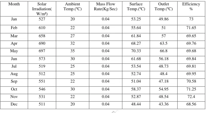
Figure.4 Temperature profile obtained in one of the simulation
that of 0.05 kg/s. The reason for that is exposure time. Air is in contact with collector surface for more time for lower flow rate. Figure 4 shows the temperature profile obtained in one of the simulation
Figure.5 Variation of outlet temperature for different mass flow rates
Figure 5 shows the variation of outlet temperature for different months. It shows two curves. One curve shows the variation of outlet temperature for air mass flow rate of 0.04 kg/s and other for 0.05 kg/s
Figure.6 Variation of collector surface temperature for different mass flow rates
Figure 6 shows the variation of collector surface temperature for different months. It shows two curves. One curve shows the variation of collector surface
temperature for air mass flow rate of 0.04 kg/s and other for 0.05 kg/s.
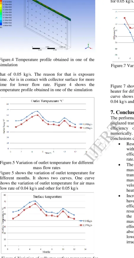
Figure.7 Variation of efficiency of solar air heater for different mass flow rates
Figure 7 shows the variation of efficiency of solar air heater for different months. It shows two curves. One curve shows the variation for air mass flow rate of 0.04 kg/s and other shows variation for 0.05 kg/s.
7. Conclusion
The performance of solar air heating system based on unglazed transpired collector has been discussed. The efficiency of an UTC has been investigated numerically. After studying the results obtained the conclusions can be stated as:
Results show that temperature rise decreases with increasing air flow rate, while collector efficiency increases with increasing air flow rate.
The efficiency increases with increasing air mass flow rate. This is because the heat transfer capacity depends directly on the mass flow rate, which induces higher velocities through the perforations and more heat transfer from the plate to the air.
Increasing the irradiation level seems to have a very limited effect on the collector efficiency for both mass flow rates. Still, the results show a small increase in efficiency as the irradiation intensity decreases for both mass flow rates. Nevertheless, this small effect may be due to the reduction of the absorber plate temperature, resulting in lower losses from the collector at low irradiation.
IJERT
IJERT
8. References
[1] Chongjie Wang,Zhenzhong Guan, Xueyi Zhao,Delin Wang, Numerical Simulation Study on Transpired Solar Air Collector.Renewable Energy Resources and a Greener Future Vol.VIII-3-4
[2] Messaoud Badache, Daniel Rousse, Stéphane
Hallé, Guillermo Quesada, Yvan Dutil, Experimental and two-dimensional numerical
simulation of an unglazed transpired solar air collector,2012
[3] K. Visagavel and P.S.S. Srinivasan,Experimental investigation on solar air heater assisted natural ventilation in single-sided ventilated room, Indian Journal of Science and Technology Vol. 3 No. 7 (July 2010)
[4] Hoy-Yen Chan, Saffa Riffat, Jie Zhu,Experimental performance of unglazed transpired solar collector for air heating: p 1853-59. [5]Lixin Gao ,Hua Bai, Xiumu Fang, Experimental study of solar air heating system based on unglazed transpired collector ,Proceedings of the ASME 2011 5th International Conference on Energy Sustainability ES2011 August 7-10, 2011, Washington, DC, USA
[6]P. T. Saravanakumar,K. Mayilsamy and M. Mohanraj, Numerical study and thermal performance of the flat plate solar air heaters with and without thermal storage .VOL. 7, NO. 4, APRIL 2012:467-71 [7]Thakur Sanjay Kumar,N S Thakur Anoop Kumar,Vijay Mittal, Use of artificial roughness to enhance heat transfer in solar air heaters – a review ,Journal of Energy in Southern Africa • Vol 21 No 1 • February 2010:p 35-51
[8] Messaoud Badache, Ste´phane Halle´, Daniel Rousse, A full 34 factorial experimental design for efficiency optimization of an unglazed transpired solar collector prototype
[9] J. Deans, Saffa Riffat, Jie Zhu,Experimental performance evaluation of unglazed transpired solar collector for air heating: p 1853-59
[10]M. Augustus Leon, S. Kumar, Mathematical modeling and thermal performance analysis
of unglazed transpired solar collectors,Solar Energy 81 (2007) 62–75
[11] S. J. Arulanandam,K. G. Terry Hollands and E. Brundrett, CFD Heat transfer analysis of the transpired solar collector under no-wind conditions,
Solar Energy Vol. 67, Nos. 1–3, pp. 93–100, 1999 [12]Aman Soi, Ranjit Singh, Brij Bhushan Effect of roughness element pitch on heat transfer and friction characteristics of artificially roughened solar air heater duct,International Journal of Advanced Engineering Technology, IJAET/Vol.I/ IssueIII/Oct.-Dec.2010/339-346
[13] Sadegh Motahar, Ali Akbar Alemrajabi, An Analysis of Unglazed Transpired Solar Collectors,Vol.13 (No. 4), pp. 153-160, 2010
[14] Bhaskar Joshi, Ranjit Singh, and Brij Bhushan, Effect of longway length of roughness element on performance of artificially roughened solar air heater duct. IJAET/Vol.II/ Issue III/July-September, 2011/130-136
[15] L. H. Gunnewiek,. G. T. Hollands and E. Brundrett ,Effect of wind on flow distribution in Unglazed Transpired plate collectors. Solar Energy
Vol. 72, No. 4, pp. 317–325, 2002
[16] C Kutscher and C Dymonds, Development of a flow distribution and design model for Transpired Solar Collectors. Solar Energy Vol. 60, No. 5, pp. 291-300, 1997
[17]Ahmed Elhakem Walid Aissaa, Mostafa El-Sallak ,An experimental investigation of forced convection flat plate solar air heater with storage material.
[18]Ministry of Non Renewable Energy India