Analysis and control of multi–area HVDC
interconnected power systems
by using virtual inertia
Elyas Rakhshani
ADVERTIMENT La consulta d’aquesta tesi queda condicionada a l’acceptació de les següents condicions d'ús: La difusió d’aquesta tesi per mitjà del r e p o s i t o r i i n s t i t u c i o n a l UPCommons (http://upcommons.upc.edu/tesis) i el repositori cooperatiu TDX (h t t p : / / w w w . t d x . c a t /) ha estat autoritzada pels titulars dels drets de propietat intel·lectual únicament per a usos privats emmarcats en activitats d’investigació i docència. No s’autoritza la seva reproducció amb finalitats de lucre ni la seva difusió i posada a disposició des d’un lloc aliè al servei UPCommons o TDX.No s’autoritza la presentació del seu contingut en una finestra o marc aliè a UPCommons (framing). Aquesta reserva de drets afecta tant al resum de presentació de la tesi com als seus continguts. En la utilització o cita de parts de la tesi és obligat indicar el nom de la persona autora.
ADVERTENCIA La consulta de esta tesis queda condicionada a la aceptación de las siguientes condiciones de uso: La difusión de esta tesis por medio del repositorio institucional UPCommons (http://upcommons.upc.edu/tesis) y el repositorio cooperativo TDR ( http://www.tdx.cat/?locale-attribute=es) ha sido autorizada por los titulares de los derechos de propiedad intelectual únicamente para usos privados enmarcados en actividades de investigación y docencia. No se autoriza su reproducción con finalidades de lucro ni su difusión y puesta a disposición desde un sitio ajeno al servicio UPCommons No se autoriza la presentación de su contenido en una ventana o marco ajeno a UPCommons (framing). Esta reserva de derechos afecta tanto al resumen de presentación de la tesis como a sus contenidos. En la utilización o cita de partes de la tesis es obligado indicar el nombre de la persona autora.
WARNING On having consulted this thesis you’re accepting the following use conditions: Spreading this thesis by the i n s t i t u t i o n a l r e p o s i t o r y UPCommons (http://upcommons.upc.edu/tesis) and the cooperative repository TDX ( http://www.tdx.cat/?locale-attribute=en) has been authorized by the titular of the intellectual property rights only for private uses placed in investigation and teaching activities. Reproduction with lucrative aims is not authorized neither its spreading nor availability from a site foreign to the UPCommons service. Introducing its content in a window or frame foreign to the UPCommons service is not authorized (framing). These rights affect to the presentation summary of the thesis as well as to its contents. In the using or citation of parts of the thesis it’s obliged to indicate the name of the author.
PhD Thesis
Analysis and Control
of Multi–area HVDC
Interconnected Power
Systems by using
Virtual Inertia
Elyas Rakhshani
Barcelona, September 2016
Analysis and Control of
Multi–area HVDC
Interconnected Power
Systems by using
Virtual Inertia
Elyas Rakhshani
Dissertation submitted to the Doctorate Office
of the Universitat Politècnica de Catalunya in
partial fulfillment of the requirements for the
degree of Doctor of Philosophy by the
UNIVERSITAT POLITÈCNICA DE
CATALUNYA
Electrical Engineering Department
Research Center on
Renewable Electrical Energy Systems
Barcelona, September 2016
Analysis and Control of Multi–area
HVDC
Interconnected Power Systems by using Virtual Inertia
Copyright © Elyas Rakhshani, 2016 Printed by the UPC
Barcelona, September 2016
Research Projects: ENE 2011-29041-C02-01, ENE 2013-48428-C2-2-R,
ENE 2014-60228-R.
UNIVERSITAT POLITÈCNICA DE CATALUNYA (UPC) Electrical Engineering Department (DEE)
Research Center on
Renewable Electrical Energy Systems (SEER)
Rambla Sant Nebridi s/n, GAIA Research Building, UPC Campus, 08222-Terrassa, Barcelona, Spain.
Web: http://seer.upc.edu http://www.upc.edu
A
CKNOWLEDGEMENTS
I like to thank God to give me the opportunity of more learning and try to be a better person in my life. These recent years of my life, during my Ph.D., was one of the most rewarding and also challenging years that I truly had a chance for meeting and understanding the people from several countries. It enriched my life with sharing a vast variety of traditions with several cultural backgrounds.
First of all, I would like to express my deepest gratitude to my supervisor Professor Pedro Rodriguez for his guidance, patience and his great support throughout my
doctoral studies. For me it was a golden opportunity to work with him. He let me to increase my experience/knowledge in new fields which will help me in the future. Without his help, this thesis would not have been possible. He was always available to discuss my research with providing priceless comments and inspiring ideas which were/will be always advantageous in my works. As an international student, I never felt lonely due to his brilliant guidance during this period.
I also want to express my thanks to Professor Remus Teodorescu and his group at
institute of energy technology in Aalborg, Denmark for their support in part of my research during my stay in Aalborg. Thanks for sharing with me their knowledge and time.
iv Acknowledgements
Especial thanks to Professor Antonio Gómez Expósito, and Dr. Juan Manuel Mauricio at electrical engineering department of University of Seville for their valuable
academic advices in part of my studies.
I also like to say thank you to the great people at Renewable Electrical Energy Systems (SEER) research center at the Technical University of Catalonia, UPC for all of their kind support during my Ph.D., especially for Dr. Alvaro Luna, Dr. Jose Ignacio Candela, Dr. Joan Rocabert, Dr. Raúl Santiago Muñoz, Dr. Juan Ramon Hermoso
and Lidia Herrera.
Many thanks to all the people in Abengoa Research for supporting me during my Ph.D., especially Professor Manuel Doblaré, Dr. Hasan Mehrjerdi, Dr. Jimmy Faria, Dr. Mria Pilar, Dulce Mellado and Pedro Martin Sanchez.
Many thanks to my friends in Barcelona during my first years of stay that make a very good and memorable time for me: Kumars, Reza, Ramin, Hamid Reza, Mehdi, Costantino and Catalin. Also especial thanks to all of my friends and colleagues in Abengoa Research during my stay in south of Spain, especially Mohamed, Pau, Toni, Dani and Cosmin.
I also offer my truthful thanks to my previous supervisor, Prof. Javad Sadeh, who has
also given me valuable academic advices and decisive guidance.
And last, but not least, I also like to present my eternal gratitude and love to my parents, my brothers and my lovely sister for their everlasting love and continuous support. Without their supports none of my achievements would have been possible.
Elyas Rakhshani September 2016, Spain
A
BSTRACT
Virtual inertia is recognized as an inevitable part of the future modern power systems. The recent trend of research in different part of modern power systems is oriented in different methods for emulating virtual inertia and many research projects have been studied this issue. This dissertation is focused on modeling, analyzing and applying the virtual inertia concept to frequency control and Automatic Generation Control (AGC) in high-level control of AC/DC interconnected power systems. Since the virtual inertia is provided by advanced control concepts of power electronics based components, the HVDC links are the main focus of this dissertation for emulating virtual inertia.
During load and resource variation in multi-area interconnected system, AGC plays a key role and it is recognized as a very important mechanism that can facilitate various tasks, such as frequency restoration, tie-line power flow control between authority areas and economic dispatch of generation units. The tasks of frequency control and the tie line power exchanges will be established by proper operation of the AGC. The AGC concept is known as a high-level control in power transmission. This high-level control generates the set-points for all the local components, like generation units or power converter stations, which are under control by their local controllers.
AGC in multi-area interconnected power systems is experiencing several adaptions due to increasing penetration of power converter based components in the grid. In this dissertation, two different methods for emulating virtual inertia are proposed and introduced in AGC modeling and control for HVDC/AC interconnected systems.
vi Abstract
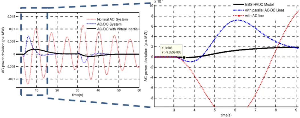
The first method is based on the Derivative Control technique. In this dissertation, the derivative control technique is used for high-level application of inertia emulation. This method of inertia emulation is developed for a two-area AGC system which is connected by parallel AC/DC transmission lines. Based on the proposed technique, the dynamic effect of emulated inertia for frequency and active power control of interconnected systems is evaluated. The effects of frequency measurement delay and Phase Locked Loop (PLL) are also considered by introducing a second-order function. Simulations results, which are obtained using Matlab software show and demonstrate how virtual inertia emulation effectively improves the performance of the power system. Detailed eigenvalue and sensitivity analyses have been also performed to support the positive effects of the proposed method.
Since the first method is based on derivation for grid frequency, the measurement of frequency is very important and application of different techniques for frequency measurements like PLL will bring some limitations for this method. Therefore, as an ultimate solution, a second method for virtual inertia emulation is introduced in this dissertation. The second method is based on the Virtual Synchronous Power (VSP) concept. The concept of VSP to emulate the dynamic effects of virtual inertia by HVDC links for high-level control applications is introduced and reflected in the multi-area AGC model. By using this proposed combination in the AGC model, the dynamic performance of the system shows a significant improvement. The active power loop control on VSP based HVDC link has a second-order characteristic which makes a simultaneous enabling of damping and inertia emulations into the system. Trajectory sensitivities and eigenvalue analyses are used to study the effects of VSP on the system stability. The effectiveness of proposed concept on dynamic improvements is tested through Matlab simulation of a multi-area test system.
Finally, it became clear that virtual inertia will add an additional degree of freedom to the system dynamics which makes a considerable improvement in first overshoot responses in addition to damping characteristics of HVDC links. Comparing the results of these two different methods of inertia emulation shows that the VSP technique has better performance with several advantages for emulating the inertia. In the VSP technique, PLL and frequency estimation are not required. Also considering the fact that simultaneous damping and inertia could be emulated, a powerful method based on VSP for improving the system dynamics during the contingencies is proposed.
F
IGURES
Figure 2.1 Consumption of industrial sectors in the world in the period of 2006–2030
14
Figure 2.2 Global energy consumption 14
Figure 2.3 Worldwide DC transmission capacity 16
Figure 2.4 Energy accessibilities and HVDC applications for transferring
16 Figure 2.5 One example of conventional power generation 18 Figure 2.6 General structure of frequency control based on UCTE 20 Figure 2.7 Participated of reserved unit for different levels of
frequency regulation
21
Figure 2.8 Levels of voltage control 22
Figure 2.9 General configurations of HVDC systems 30
Figure 2.10 Average model of MMC 32
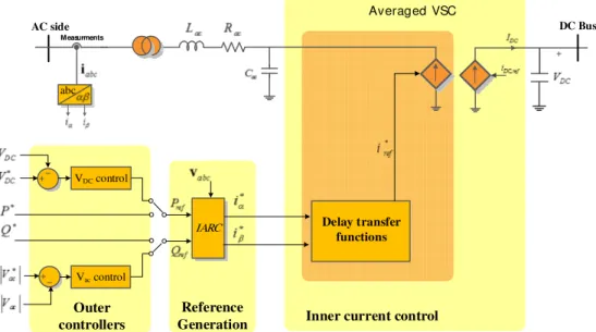
Figure 2.11 Parallel shape of MTHVDC system: (a) radial, (b) mesh 35 Figure 3.1 General structure of the VSC based HVDC control
system
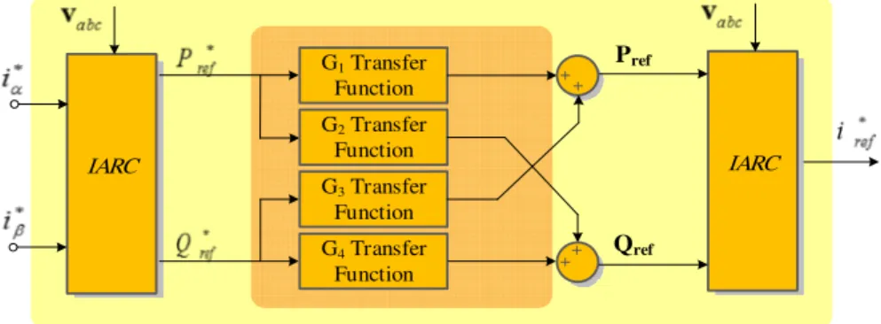
38 Figure 3.2 Structure of the average model for VSC 40 Figure 3.3 Structure of the simplified average modelling for VSC 42 Figure 3.4 Transfer functions that emulate the dynamics of inner
loop controller
43 Figure 3.5 Active power and reactive power performance 45
Figure 3.6 Three phase injected currents 46
viii Figures
Figure 3.8 Control signals of interconnected area with small signal
model of HVDC 48
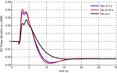
Figure 3.9 Comparisons of DC power deviation for different time
constants 49
Figure 4.1 Generic representation of the frequency dependency on
load changes 53
Figure 4.2 Frequency performance in Hz when the primary and
secondary controls are applied 53
Figure 4.3 Control continuum 54
Figure 4.40 General strategy for power sharing in AGC control 55 Figure 4.50 Block diagram representation of the generator-load in
power system
57
Figure 4.60 Turbine-governor model 58
Figure 4.70 Frequency control strategy for interconnected systems 59 Figure 4.80 A two-area system with AC connection 60 Figure 4.90 Block diagram of a small signal HVDC system 64 Figure 4.10 Diagram of SPMC with parallel HVAC and HVDC links 65 Figure 4.11 Control actions of interconnected area with small signal
of HVDC
66 Figure 4.12 A two-area system with a parallel AC/HVDC link 67 Figure 4.13 Frequency deviations of both areas. a) Area1, b) Area2 70
Figure 4.14 Active power generations. 71
Figure 4.15 DC power deviation 72
Figure 4.16 Tie-line AC power deviation 72
Figure 4.17 Eigenvalues of different systems: AC and AC/DC 74 Figure 5.10 Configuration of the test system with storage and parallel
AC/DC link
79 Figure 5.20 Proposed higher level control for HVDC-ESS Systems 81 Figure 5.30 Block diagram of the derivative inertia emulation strategy 81 Figure 5.40 A general example of injected power by storage devise 86 Figure 5.50 Load Demand changes as a disturbance at 3 and 30 sec 87 Figure 5.60 Dynamic response of frequency in Area 1 88 Figure 5.70 Dynamic response frequency in Area 2 88
Figure 5.80 Output power of Generator 1 89
Figure 5.90 Output power of Generator 2 89
Figure 5.10 Output power of Generator 3 89
Figure 5.11 Output power of Generator 4 89
ix Figures
Figure 5.13 Power variations of HVDC link for different systems 90 Figure 5.14 Emulated inertial power by derivative control method 90 Figure 5.15 Energy variations of ESS during inertia emulation 91 Figure 5.16 Status of power in ESS1 during inertia emulation 92 Figure 5.17 ACE1 response for different values of J1 95
Figure 5.18 Eigenvalue trajectory of dominant poles over J1 changes 98
Figure 5.19 Eigenvalue trajectory of dominant poles over J2 changes 98
Figure 5.20 Frequency response in Area 1 and 2 for difference control gains
100 Figure 5.21 Frequency characteristics: (a) Peak overshoot, and (b)
Settling time
100
Figure 5.22 Output power of generation units 101
Figure 5.23 Settling times of active power response for GENCO1 and GENCO2
102 Figure 5.24 Power generated by derivative control method: (a) ESS1,
(b) ESS2
102 Figure 5.25 Comparisons of peak power during virtual inertia
emulation
102 Figure 5.26 Three-dimensional presentation for sum of the
frequencies of oscillatory modes for different values of both control gains
109 Figure 5.27 Three-dimensional presentation for total damping of
oscillatory modes for change in both control gains 110 Figure 5.28 A typical control structure of grid-connected converters 111 Figure 5.29 Block diagram of derivative inertia emulation strategy 112
Figure 5.30 Basic structure of a PLL 112
Figure 5.31 Small signal model of a basic PLL 113
Figure 5.32 Higher level model of AC/DC system with derivative control and PLL
115 Figure 5.33 System frequency deviations with and without PLL 120 Figure 5.34 Dynamic response of ESS power with and without PLL 121 Figure 5.35 Dynamic response of DC power for different systems 121
Figure 5.36 Response of frequency deviations 123
Figure 5.37 Power deviations by derivative control, A) ESS1, B) ESS2
124 Figure 5.38 Dynamic performance of DC link power, considering
PLL effects
125 Figure 6.10 The configuration of simplified synchronous power 130
x Figures
controller
Figure 6.20 Electromechanical representation of synchronous power controller
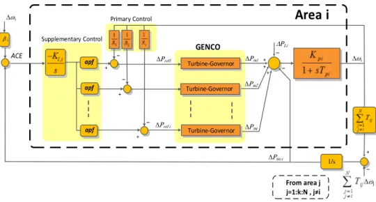
131 Figure 6.30 Basic frame of AGC in multi-area systems with a VSP
based AC/DC transmission 134
Figure 6.4 The basic frame of multi area system with multiple VSP
based AC/DC transmission 137
Figure 6.5 Control frame of the ith area in AGC implementation
connected to multiple VSP based AC/DC lines 138 Figure 6.6 Eigenvalue trajectory of dominant modes for
variations 142
Figure 6.7 Eigenvalue trajectory of system modes for variations 143 Figure 6.8 Frequency deviations in Area 1 and 2 for difference
control gain values 148
Figure 6.9 Frequency characteristics: (a) Peak overshoot, and (b)
Settling time 148
Figure 6.10 Active power generations 149
Figure 6.11 Settling times of active power response for GENCO1 and
GENCO2 149
Figure 6.12 Frequency deviations for different damping in VSP1 150 Figure 6.13 Frequency characteristics: (a) Peak overshoot,
(b) Settling time 151
Figure 6.14 Emulated power by the VSP1 151
Figure 6.15 Frequency deviations in Area 1 and 2 for difference
control gain values 152
Figure 6.16 Frequency characteristics: (a) Peak overshoot, and (b)
Settling time 153
Figure 6.17 Frequency deviations in Area 1 for different damping in VSP2
153 Figure 6.18 Emulated power by VSP2 for different damping values 154
Figure 6.19 3-D presentation for total damping of the system modes
for different values of and . 158
Figure 6.20 3-D presentation of the total damping of the system
modes for different values of and 159
Figure 6.21 3-D presentation of the total damping of the system
modes for different values of and 160
Figure 6.22 Dynamic response of frequency deviations 161 Figure 6.23 Output power generation; a) GENCO1, b) GENCO2, c) 162
xi Figures
GENCO3, and d) GENCO4
Figure 6.24 Power deviations with the derivative method and the VSP control method
163 Figure 6.25 The configuration of the three-area power system with
HVDC link. 165
Figure 6.26 Dynamic response of frequency deviations for three-area system; A) Area1, B) Area2 and C) Area3.
167 Figure 6.27 Power generations in Area1; A) GENCO11, B)
GENCO12, and C) GENCO13. 168
Figure 6.28 Power generations in Area2; A) GENCO21, B)
GENCO22, C) GENCO23, and GENCO24. 169
Figure 6.29 Power generations in Area3; A) GENCO31, B)
GENCO32, and C) GENCO33. 170
Figure 6.30 Tie-line AC power exchanges; A) Line 1-2, A) Line 1-3,
and A) Line 2-3. 171
Figure 6.31 Power deviation from VSP based HVDC system; VSP1
in Area1 and VSP3 in Area3. 172
Figure 6.32 Required energy by VSP based HVDC stations. 172 Figure 6.33 Single-line diagram of the studied four-area
interconnected system. 173
Figure 6.34 Sensitivities of important elements to the system modes. (A) VSP elements in 19th row of A matrix, (B) VSP
elements in 21th row of A matrix.
177 Figure 6.35 Mode shape. (a) λ1,2 (b) λ14,15. 178
Figure 6.36 Frequency deviations of different areas. (A) Area1, (B)
Area2, (C) Area3, (D) Area4. 179
Figure 6.37 Generated power deviation of all generation units; (A) GENCO1, (B) GENCO2, (C) GENCO3 and (D) GENCO4.
180 Figure 6.38 Deviation of AC tie-line power for different lines. 181
Figure 6.39 Power variation of VSP stations. 182
T
ABLESTable 2.10 Comparison of transmission with different technologies 28
Table 4.10 GENCOs parameters 69
Table 4.20 Parameters of control area 70
Table 4.30 Eigenvalues comparison 73
Table 4.40 Eigen index comparisons of different systems 73 Table 5.10 Control parameters considering derivative control. 87 Table 5.20 Eigenvalues for different values of J1 (with J2=0.093) 95
Table 5.30 Eigenvalues for different values of J2 (with J1=0.870) 97
Table 5.40 Eigenvalues comparison for different systems 99 Table 5.50 The damping value of oscillatory modes for different control
gain
100 Table 5.60 The frequency of oscillatory modes for different control gain 101 Table 5.70 Absolute value of sensitivity of each mode for important
elements of A matrix
107 Table 5.80 Absolute value of sensitivity of each mode for important
elements of A matrix
108
Table 5.90 Summary of eigen sensitivity analysis 108
xiv Tables
Table 6.10 Control parameters for studied two-area AC/DC model 140 Table 6.20 Eigenvalues of two-area system for different values of ωn1 141
Table 6.30 Eigen index for different values of ωn1 143
Table 6.40 Eigenvalues of two-area system for different values of 144
Table 6.50 Eigen index for different values of 144
Table 6.60 Eigenvalues of a two-area system for different values of 145
Table 6.70 Eigen index for different values of 146
Table 6.80 Eigenvalues of a two-area system for different values of 146
Table 6.90 Eigen index for different values of 147
Table 6.10 Eigen index comparison for different methods of emulating
the inertia 147
Table 6.11 Normalized sensitivity of each mode for important elements of the A matrix
156 Table 6.12 Normalized sensitivity of each mode for important elements
the A matrix
157
Table 6.13 Summary of eigen sensitivity analysis 158
Table 6.14 Eigenvalue comparisons for different two-area systems 164 Table 6.15 Parameters of the three-area test system 166 Table 6.16 Control parameters for studied 3-area AC/DC model 166 Table 6.17 Parameters of the studied four-area interconnected system 174 Table 6.18 Eigenvalues of the studied four-area system 176 Table 6.19 VSP based HVDC control parameters in studied 4-area
A
CRONYMSAGC Automatic Generation control AVR Automatic Voltage Control ACM Active Control and Management APF Area Participation Factor
DG Distributed Generation
DPS Distributed Power System DISCO Distribution Company
ESS Energy Storage System
GA Genetic Algorithm
GENCO Generation Company
HVDC High Voltage Direct Current ISE Integral of Squared Error ISO Independent System Operator
LFC Load Frequency Control
MMC Multi Modular Converter
POD Power Oscillation Damping PSO Particle Swarm Optimization
PLL Phase Locked Loop
RES Renewable Energy Resource
xvi Acronyms
SMES Supper Magnetic Energy Storage SPC Synchronous Power Controller SQP Sequential Quadratic Programming TRANSCO Transmission Companies
VIU Vertically Integrated Utility VSG Virtual Synchronous Generator VSC Voltage Source Converter VSP Virtual Synchronous Power
C
ONTENTS
1 Introduction………..
1.1 Goals and objectives………..…… 1.2 Contributions of the thesis………. 1.3 Thesis organization……… 1.4 Publication……….
2 State of the Art……….
2.1 Introduction……….…... 2.1.1 Deregulation……….. 2.1.2 Growth of renewable energy………. 2.1.3 Growth of DC interconnections……… 2.2 Modern Power System………... 2.2.1 Conventional power system……….. 2.2.2 Conventional energysources……… 2.2.3 Power system deregulation and its requirements……….. 2.2.4 Ancillary services……….. 2.2.5 Importance of distributedpower systems………. 2.3 AdvancedDCinterconnection……….. 2.3.1 HVDCconfigurations………... 2.3.2 Classic HVDC………... 2.3.3 VSC HVDC………... 2.3.4 Control ofHVDCsystems……… 2.3.5 Multi-terminal interconnected HVDC systems……….
3 Review on HVDC Control for Power Systems
Applications……….. 3.1 Two-terminal HVDC………. 5 6 7 8 10 13 13 13 14 15 18 18 18 19 19 24 28 29 31 31 34 34 37 37
xviii Contents 3.2 Averaged modeling and control structure of HVDC system………. 3.3 Simplified model and control structure of HVDC system………. 3.4 Small-signal HVDC modeling for higher level control design………….
4 Automatic Generation Control of Interconnected
Systems………..
4.1 Introduction……… 4.2 Fundamental of frequency control………. 4.2.1 Primary active power/frequency control………... 4.2.2 Supplementary higher level control………. 4.3 Mathematic dynamical model………
4.3.1 Generator-loaddynamic model……… 4.3.2 Governor-turbine model………... 4.4 Multi-area interconnected AGC systems………...
4.4.1 Areainterface………
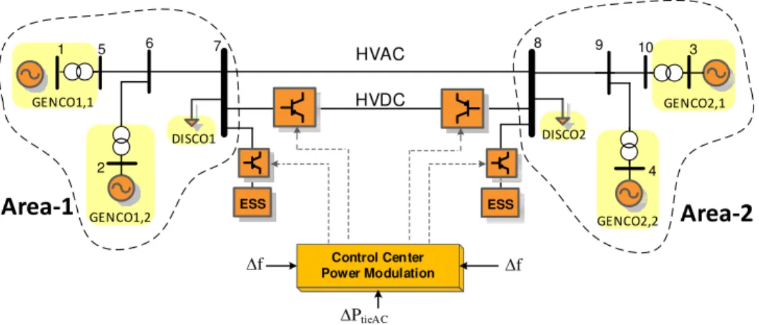
4.4.2 Dynamic model oftwo-area AC system………... 4.5 Multi-area interconnected AGC with HVDC model………. 4.5.1 Supplementary power modulation controller for HVDC……….. 4.5.2 Dynamic model of two-area system with SPMC………... 4.5.3 Simulation of two-area power systemexample………
5 Virtual Inertia for Interconnected System using
Derivative Control………
5.1 Review and SOA in thesubject………. 5.2 High level controlfor inertia emulation byderivative control………….. 5.2.1 The concept of virtual inertia.………... 5.2.2 Modelling of inertia emulation in AC/DC AGC system... 5.2.3 Rating the required energy for inertiaemulation……….. 5.3 System analyses………. 5.3.1 Eigenvalueanalyses………..……… 5.3.2 Sensitivityanalyses………... 5.4 Dynamic effects ofmeasurements………. 5.4.1 Dynamic model of PLL………. 5.4.2 Model of two-area system with derivative control and
PLLdynamics……….. 5.4.3 Analyses the dynamic effects of second-order PLL
onAGC response ………. 39 42 47 51 51 52 53 53 56 56 57 59 59 60 64 64 67 69 75 76 78 78 78 84 93 93 99 111 111 115 120
Contents xix
6 Virtual Inertia Emulation for Interconnected Systems
using VSP………..
6.1 Review and SOA in the subject………. 6.2 Higher level control for inertia emulation by VSP……… 6.2.1 Virtual synchronous power strategy………. 6.2.2 Modelling of VSP based inertia emulation in AC/DC interconnected AGC system……….. 6.2.3 Generalized AGC with multiple VSP based HVDC links……… 6.3 System analysis………..
6.3.1 Eigenvalueanalysis……….... 6.3.2 Sensitivityanalyses……… 6.4 Comparison and simulation results……… 6.4.1 Two-area system with comparisons……… 6.4.2 Case study of three-area system………. 6.4.3 Case study of four-area system………...
7 Conclusions………...
7.1 Introduction……… 7.2 Main conclusions and thesisachievements………... 7.2 Future work……… References……….. 127 128 130 130 133 137 140 140 147 161 161 165 173 183 183 185 188 191
C
HAPTER
1
.
1
Introduction
ower systems are experiencing a fast revolution considering power market and deregulations and high penetration of power electronic based components like renewable power sources (distributed generation, Wind, PV with energy storage technologies). These changes make power systems very complex with more uncertainties. Generally renewable resource of energy will have some stochastic nature that eventually could have different effects on power grid. Managing new modern power systems in a deregulated scheme with high penetrate renewable resources is difficult and the matter of inertia from stability point of view is very important [1.1]-[1.8]. In order to cope with new challenges in modern power systems more detailed research in this filed is necessary.
This dissertation is part of research projects at the ABENGOA Company, Abengoa Research department, in collaboration with SEER research center at UPC University. The title of the thesis is “Analysis and Control of Multi-area HVDC Interconnected Power Systems by using virtual inertia”. Since several topics have been covered during this project, the main focus of this dissertation is related to modeling, analyzing and application of virtual inertia concept in frequency stability and AGC issue in high level control of AC/DC interconnected power systems. The AGC concept is known as high level control at the transmission systems. This high level control will generate the set-points for all the local components, like generation units or power converter station, which are under control by their local controllers [1.9]-[1.11].
6 1. Introduction
Since the virtual inertia is provided by advanced control concepts for power electronic based components [1.12]-[1.14], the HVDC links are the main focus of this dissertation for emulating the inertia. Global oscillation is caused by interaction among large groups of generators, which are spread out throughout a large geographical area. This type of oscillations has widespread impact and can lead to partial or full blackout. Application of HVDC links in parallel with AC links is one of the ways which can improve the negative impacts of this kind of oscillations [1.15]-[1.17].
Modern power system control and analysis with high penetration of PV resources and with DC interconnections are increasingly under consideration. For providing a better performance during operation and also to increase the stability of the system, different installations with new technologies are necessary, e.g., advanced components of power electronics, HVDC links and Flexible AC Transmission Systems (FACTS) equipment in the power system. The main application area for HVDC is the interconnection between systems which cannot be interconnected by AC link because of different operating frequencies or different frequency controls. By means of global RE integration and competitive markets, it would be necessary to equip the network with several DC interconnections at high voltage level between the areas. Therefore, in addition to more stability in the whole system by applying DC interconnections, there is a better possibility to transfer more power for any kind of long distance link. Providing additional inertia by means of power electronic components (like HVDC station) is another advantage that could provide different ancillary services like providing the damping and virtual inertia for frequency control improvements. The main goal, objectives and contributions in this thesis are as follows:
1.1
Goals and Objectives
As stated, the matter of inertia and analyzing the impact of virtual inertia in multi area power system is very important. Therefore, the main goal of this thesis is the improvement of dynamic response and overall performance of Multi Area Power Systems (MAPS) using Virtual Synchronous Power (VSP) concept, considering HVDC links of interconnected systems. The main focus is related to frequency control stability analysis of multi area interconnected systems. Based on this explanation, here are the main objectives of this thesis:
1- To present a novel approach for inertia emulation through the VSP based HVDC transmission systems. This control strategy proposes a new method for power converter control in HVDC link. Let them behaving as a synchronous
1.1 Goals and Objectives 7
generator with the ability of emulating synchronous inertia during the transients in HVDC stations without the drawbacks of conventional generators. This new application of VSP in power system transmission provide more flexibility to the power system. It will increase the mitigation of power system oscillation by emulating inertia and sufficient damping to the system through HVDC interconnections.
2- To propose a new approach of frequency stability analysis in multi area AGC system considering the derivative term of grid frequency for emulating inertia in the interconnected AC/DC systems.
3- To propose a new approach of frequency stability analysis in multi area AGC system adding the VSP concept in HVDC links of interconnected systems. The proposed models should provide a systematic modeling and control technique of a large scale interconnected power system and specifically should be devoted to frequency support and power oscillation damping (POD) by means of parallel AC/DC transmission line and Energy Storage Systems (ESS) technologies in AGC systems of power industry.
4- To propose a model which is very useful for pre-evaluation of dynamic effects of converter stations of HVDC link in higher level control design for power systems applications.
5- To preform dynamic analyses for multi area AGC model with eigenvalue and sensitivity analyses considering virtual inertia effects on the overall system performance.
1.2
Contributions of the Thesis
The contributions of the research work reported in this thesis can be grouped into the following issues:
- Proposing new approach on emulating the virtual inertia for AGC analysis in multi area power systems. This virtual inertia will bring more flexibility to the transmission system for damping the inter-area oscillation and emulating the inertia.
- Improving the frequency stability and control of generation in multi-area interconnected power systems by adding the virtual inertia concept. This virtual inertia is contributing during transients caused by load variations.
8 1. Introduction
- Proposing a new application of virtual inertia emulation based on derivative control for AGC analyses of interconnected power systems. Proper modeling for higher level control applications with proper coordination between DC link and AGC is provided.
- Incorporating the effects of frequency measurements and PLL dynamics on AGC analyses of interconnected power systems. The effects of PLL is introduced for the system with virtual inertia based on derivative control technique.
- Proposing a new application of VSP technique for higher level application in AGC power system. This method can be used to provide possible inertia in to the modern scenario of power industry for frequency supports and POD tasks. By means of proposed technique based on VSP control, better dynamic performance compared to other methods of inertia emulation like derivative control is obtained. The proposed control of VSP is a power electronics based synchronous generator which is naturally synchronized with the electrical grid by balancing the exchange of power with AC grid. Therefore, it does not require any external synchronization system, such as a PLL, to work. Therefore all the limitations and dependencies to PLL and frequency measurements will be avoided.
- In this study by means of proposed models, it is possible to have a clear image about the system conditions and required energy or power references considering the control issue of AC/DC interconnected system. Proposed model could be extended to any type of multi area system with different complexity.
1.3
Thesis Organization
The thesis will continue by a complete state of the art on conventional power system control and its modifications to the modern power systems in Chapter 2. In this Chapter the importance of power electronic based components in the future of power industry is explained. It will continued by reviewing the main control functions in power system considering the main ancillary services that could be offered in modern scenario of power system. Brief review about HVDC application and its control structure is also presented by the end of this Chapter.
In Chapter 3, a brief presentation about two-terminal HVDC links and its control
functions are presented. Different modeling for power system applications is also presented. The main focus is related to averaged model of voltage source converters and
1.3 Thesis organization 9
simplifications. The small signal model of HVDC link which used in this thesis is the last part of this Chapter.
The main focus of Chapter 4 is to present the fundamental of frequency control in
power grid and is explaining the dynamic model of multi-area AGC system. The conventional AC model and the modified model considering HVDC link based on supplementary power modulation control (SPMC) is presented. Mathematical equations for multi-area interconnected AGC system are presented and a general simulation for two-area system is the last part of this Chapter.
In this thesis two different methods for emulating virtual inertia is proposed and introduced in AGC modeling and control for HVDC/AC interconnected systems. The first method is based on derivative control and the second methods is based on virtual synchronous power concept. In addition to incorporating the coordinated model of DC link in AGC model, these methods of emulating virtual inertia are the main contribution of this thesis. Both methods are presented and analyzed in Chapters 5 and 6, respectively.
Therefore, in Chapter 5, the derivative control technique is proposed for higher level
application of inertia emulation. This method of inertia emulation is developed for two-area AGC systems which is connected by parallel AC/DC transmission lines. Based on the proposed technique, the dynamic effect of inertia emulated by storage devices for controlling the frequency and active power variations are evaluated. The effects of frequency measurement delay and PLL effects are also considered by introducing a second-order function. Simulations results using the Matlab software, shows and demonstrate how virtual inertia emulation can effectively improve the performance of the power system. A detailed eigenvalue and sensitivity analyses have been also performed to support the positive effects of proposed method.
In Chapter 6, the second method for virtual inertia emulation is introduced. The
second method is based on VSP concept. The concept of VSP to simulate the dynamic effects of inertia emulations by HVDC links for higher level control applications is introduced and reflected in the multi-area AGC model. With using this proposed combination in AGC model, the dynamic performance of the system shows a significant improvement. Trajectory sensitivities and eigenvalue analyses are used to analyze the effects of VSP on the system stability. The effectiveness of proposed concept on dynamic improvements is tested through Matlab simulation of multi-area test system.
Finally, it became clear that virtual inertia will add additional degree of freedom to the system dynamics which makes a considerable improvement in first overshoot responses
10 1. Introduction
in addition to damping characteristics of HVDC links. Comparing the results of these two different methods of inertia emulation shows that the VSP technique has better performance with several advantages for emulating the inertia. In the VSP technique, PLL and frequency estimation are not required.
Finally, the dissertation is summarized in Chapter 7. In this Chapter the main
conclusions considering the possible future works are presented.
1.4
Publications
Patent:
- Jorge Martinez Garcia, Pedro Rodriguez Cortes, Elyas Rakhshani; “Virtual Power Controller and Method for Multi-terminal HVDC Interconnected
Network,” European Patent, 2016.
Book chapter:
- E. Rakhshani, P. Rodriguez, "Active Power and Frequency Control
Considering Large-Scale RES", in Large Scale Renewable Power Generation,
Springer, pp. 233-271, 2014.
Journals (2011-2016):
- E. Rakhshani, D. Remon, A.M. Cantarellas, J.M. Garcia and P. Rodriguez,
“Virtual Synchronous Power Strategy for Multiple HVDC Interconnections of Multi-Area AGC Systems”, IEEE Transactions on Power Systems, 2016,
DOI: 10.1109/TPWRS.2016.2592971.
- E. Rakhshani, D. Remon, A. Mir Cantarellas, and P. Rodriguez, “Analysis of
Derivative Control Based Virtual Inertia in Multi-Area HVDC Interconnected AGC Power Systems”, IET Generation Transmission & Distribution, vol. 10,
no. 6, pp. 1458-1469, 2016.
- E. Rakhshani, D. Remon, A.M. Cantarellas, J.M. Garcia and P. Rodriguez,
1.4 Publications 11
HVDC links of Interconnected Power Systems”, Electric Power Systems
Research, Elsevier, vol. 141, pp. 246–263, 2016.
- E. Rakhshani, D. Remon, and P. Rodriguez, “Effects of PLL and Frequency
Measurements on LFC problem in Multi-Area HVDC Interconnected Systems”,
International Journal of Electrical Power and Energy Systems, Elsevier, vol.
81, pp. 140-152, 2016.
- E. Rakhshani, “Intelligent linear quadratic optimal output feedback regulator
for a deregulated automatic generation control system”, Electric power
Component & systems, Vol. 40, No. 5, pp. 513-533, 2012.
Conference (2011-2016):
- E. Rakhshani, D. Remon, A.M. Cantarellas, P. Rodriguez, "Frequency control
of HVDC Interconnected systems considering derivative based inertia emulation", IEEE PES General Meeting, Boston, 2016.
- E. Rakhshani, D. Remon, A.M. Cantarellas, H. Mehrjerdi, P. Rodriguez,
"Derivative based Inertia Emulation of Interconnected Systems Considering Phase-Locked Loop Dynamics,” IEEE PES General Meeting, Boston, 2016.
- E. Rakhshani, D. Remon, A.M. Cantarellas, K. Rouzbehi, P. Rodriguez, "Integration of renewable generation for frequency support of HVDC/AC interconnected systems under power market scenario", IEEE PES General
Meeting Conference & Exposition, pp. 1-5, 2014.
- D. Remon, A.M. Cantarellas, E. Rakhshani, I. Candela, P. Rodriguez, "An active power synchronization control loop for grid-connected converters", IEEE
PES General Meeting Conference & Exposition, 2014.
- E. Rakhshani, A.M. Cantarellas, D. Remon, P. Rodriguez, I. Candela,
"Modeling and control of multi modular converters using optimal LQR controller with integral action", IEEE Energy Conversion Congress and
12 1. Introduction - E. Rakhshani, A.M. Cantarellas, D. Remon, A. Luna, P. Rodriguez, "PSO-based LQR controller for multi modular converters", IEEE ECCE Asia
Downunder (ECCE Asia), pp. 1023-1027, 2013.
- E. Rakhshani, A.M. Cantarellas, P. Rodriguez, R. Teodorescu, "Comparative
Study on Power Transmission Modeling in Large Scale AGC Power System",
International Conference on Renewable Energy and Power Quality (ICREPQ),
Bilbao, Spain, 2013.
- E. Rakhshani, A. Luna, J. Sadeh, P. Rodriguez, "PSO Based Optimal Output Feedback Controller for Two-Area LFC System", 20th Mediterranean
Conference on Control and Automation, (MED), Barcelona, Spain, 2012.
- E. Rakhshani, A. Luna, K. Rouzbehi, P. Rodriguez, ''Application of Imperialist
Competitive Algorithm to Design a New Optimal Controller for Two-Area Deregulated LFC System", IEEE Industrial Electronics Conference, IECON,
Canada, 2012.
- E. Rakhshani, A. Luna, K. Rouzbehi, P. Rodriguez, "Effect of VSC-HVDC on
Load Frequency Control in Multi-Area Power System", IEEE Energy
C
HAPTER
2.
2
State of the Art
nergy is a very important issue in all around the world while energy demands increased incessantly in the last decade. Beside of problems associated to energy production from coal, the new trend in the world are to increase the share of renewable energy sources in the production of electrical energy. In parallel, the concept of deregulation and competition in energy have forced scientists and engineers to think deeper about the challenges related to the paradigm change in large scale power system [2.1]-[2.2].
2.1
Introduction
2.1.1
Deregulation
In the deregulated scenario of power industry, the vertical structure is replaced by a fully deregulated power system with many independent producers. Therefore, in many countries, Vertically Integrated Utilities (VIU) are not exist anymore. In the competitive scenario of power industry, Transmission Companies or (TRANSCOs), Distributed Companies or (DISCOs) and Generation Companies or (GENCOs) are the main players which are working under supervision of Independent System Operator (ISO) [2.3]-[2.5]. In the deregulated power system, competition is the main goal of energy privatization. In this way, access to the transmission system and the possibility of presenting ancillary services are two relevant issues in this environment, where there can exist a lot of power producers (like DGs) and DC interconnections (like VSC-HVDC). In this kind of environment, DC interconnections are very important to act as corridors to transfer power based on possible scenarios.
14 2. SOA
2.1.2
Growth of renewable energy
According to Figure 2.1, energy consumption in the industrial sector will be rapidly increased in the next decades but, in parallel, new policies will be set around renewable energies. So by this increment, it is obvious that traditional sources of energy have to be replaced by renewable source of energy while, at the same time, necessary infrastructures and new technologies should be implemented until 2030 [2.6].
2025 2030 2010 2015 2020 0 10,000 20,000 30,000 40,000 50,000 60,000 70,000 80,000 54,469 59,567 64,284 68,474 71,961 Year E n er g y C o n su m p ti o n ( ZW )
Figure 2.1. Consumption of industrial sectors in the world in the period of 2006–2030 [2.6].
For example, solar power is a type of energy with great future potential. Based on European Photovoltaic Industry Association (EPIA) and International Energy Agency (IEA) reports, the world cumulative PV capacity, for example, reach at least to 178 GW, which was sufficient enough to supply at least 1 percent of global demand of electricity. While for 2015, the global deployment of about 55 GW is expected and the installed capacity should be double or triple around 500 GW from now until 2020.
50.00 1970 1980 1990 2000 2010 2020 2030 2040 2050 2060 0 100.00 150.00 200.00 250.00 T W h / Y e a r Tot al Fossil Renew able Nuclear
2.1 Introduction 15
As shown in Figure 2.2, the electricity based renewable will be faced with a remarkable increase by 2030 [2.7]-[2.9] while, at the same time, we can see a significant growth of global energy consumption [2.7]-[2.8]. This suggest that renewable type of energy can play a very important role in the future modern power system. However, in order to enable distributed generation as a major source of energy in the near future, it is very important to make an intensive effort for developing such advanced technologies.
2.1.3
Growth of DC interconnections
Nowadays, we are facing with growth and extension of AC systems and as a result with more complexity and stability problems. As it was explained in previous Sections, increasing level of distributed generations and deregulated energy markets get in conflict with increasing rate issues with increasing rates of energy consuming, making necessary to apply more advanced technologies. One of the way for increasing the overall stability and reliability in large-scale power system, is to interconnecting the neighboring areas. These interconnections could be performed by HVDC links especially in the case connections between asynchronous areas or in case of very large distance connection between a source of energy and demand centers. In addition, the actions of HVDC links, as a secure and safe corridors for fast transferring the power, will be very important in the liberalized scenario of power markets. All of these new challenges could be faced up with advanced technologies of HVDC transmissions.
One of the main advantages of DC links is related to direct and fast power flows between two areas without overloading of existing AC system.
Furthermore, in addition to higher reliability, the HVDC links can act as a useful firewall during cascaded disturbances. Therefore, it can prevents overall blackouts. It should be noted that, in some applications, the HVDC or hybrid interconnections, consisting of HVAC and HVDC links, turned into the preferred solution. The HVDC link between Sweden and island of Gotland is known as a first commercial application of DC link in 1954 [2.10]. After that, a huge increase for HVDC application can be observed all around the world. As shown in Figure 2.3, HVDC become a reliable technology and more than 120 GW HVDC transmission capacities have been installed worldwide up to now. There will be a huge increasing in HVDC applications in future power systems and researching in this area is very important.
As shown in Figure 2.4, energy capacities vary from one part of the world to other, making transportation of this energy to load centers, especially based on open market, a very interesting issue. For example, in north of Africa there are a huge area with an
16 2. SOA
outstanding capability for solar energy and applying DC links from north of Africa to south of Europe is one of the main important applications in this field.
Figure 2.3. Worldwide DC transmission capacity.
Solar Power > 10 .. 20 GW Wind Power > 20-40 GW Hydro Power > 10-30GW
Figure 2.4. Energy accessibilities and HVDC applications for transferring.
Based on this brief introduction, what is clear is that future power systems are a very challenging issue with high penetration of DGs, DC transmission and high complexity.
0 50 100 150 200 250 300 1975 1980 1985 1990 1995 2000 2005 2010 2015 2020 G W
2.1 Introduction 17
Scientists and engineers have concentrated their research efforts to change such challenging electrical scenario. Advancements in technologies, such as the use of modern power processing systems, energy storage and control techniques in high-power applications, as well as high penetrations of renewable source of energies and liberalization of power markets, have led to a reformulation of the conventional power systems, moving to a more flexible scheme, which is broadly known as modern power systems. Modern distributed power systems are still going through their first steps nowadays. So far, the most significant advancement is related to the generation side. DGs are proposed by some new generation approaches considering the fact that generated electricity should be as close as the load centers. However, many other fields still remain in a very initial state. It is the case of the HVDC Supergrids, which are planned to act as energy corridors between different countries and to integrate far distance renewables. Even though HVDC is reached to the level that is ready for different application with capability of long distance transmissions for large amounts of power, the typical projects including multi-terminal HVDC connections are not yet an the most optimum industrial reality. Energy storage systems is another technology which is expected to become essential in future power systems. EES will allow improving the performance of the system by optimizing energy flows, attenuating power disturbances, and minimizing negative effects associated to the intermittent behavior of RES. It should be noted that the EES systems have attracted lots of attentions in the recent years and more large scale application are predictable by the future.
It should be noted that, the capability of generating and processing power in modern power system must be supported with a significant level of computational capacity considering the whole structure of the system. The control patterns which is currently in use for conventional systems cannot be extended to a modern scenario, which makes necessary to look for new solutions.
18 2. SOA
2.2
Modern Power System
Conventional power systems is changed and developed into a rapid steps of deregulation. Integration of power electronic based components, distributed applications of energy storage and different concerns regarding climate change and high penetration of renewable energy resources like PV in the power system are the main factors of interests in modern power system studies [2.11].
2.2.1
Conventional power system
In conventional power system, the utilities are typically managed by government. In other words, traditional power system was a kind of vertical structure which maintains a large amount of physical components, considering all the generation units and transmission systems. The utility has the control of all the generators and based on real time power flow a new set-point to all the units will be allocated for different situation. That is clear that this type of unchallenged situation is not fair and considering a huge increment in the amount of distributed generation and independent power producers, a new restructure and kind of deregulation was necessary for power system [2.3].
2.2.2
Conventional energy sources
Generally, the main source of energy in conventional generation are related to the base power generation (fossil fuel or coal based generations or nuclear power plants) and fast ramping generation (like hydro power or gas turbines). Figure 2.5 shows one the most common scenarios in conventional generation which is based on coal fired power.
HP LP Transmission Distribution Thermal/Nuclear Power Plants Generation Tubrine-generator system SG
2.2 Modern power system 19
The generated power in this type of units will be transmitted to load centers with high voltage transmission line or sometimes with under-ground cables.
In such generation system, coal will be prepared and passed to a boiler. Usually a boiler will be a complex system consisting of many sequences for abstraction of energy from the fuel. [2.11].
2.2.3
Power system deregulation and its requirements
As it was explained, GENCOs, DISCOs and TRANSCOs considering ISO are the main players of competitive scenarios of power market [2.3]-[2.5]. The main goal of restructured power system is competition. Therefore, the main issue in such scenario is the possibilities of open access to the transmission system and the possibility of providing different ancillary services.
It is very important to involve the ISO in a way that a fair transmission system be provided for all the players of the market. In this way, it would be possible that each GENCO have the possibility of making individualized contract for each specific DISCO in the market. Ancillary services should be also involved as well as competitiveness of the system to provide a high quality electricity to the consumers. It should be note that, in modern power system, ancillary service could be kind of complementary task in terms of a grid operation with high penetration of renewable sources. It can reduce the level of uncertainty which will be produced by renewables [2.12].
2.2.4
Ancillary services
Ancillary services are known as individual parts of electric services that required to provide sufficient support to energy supply, delivery of high quality power in reliable manner and acceptable operation for the transmission system. Some of the main parts of the ancillary services are related to operation of reserve capacities, regulation of reactive power, voltage regulation and active power or frequency regulation [2.3].
2.2.4.1
Active power balance and frequency control
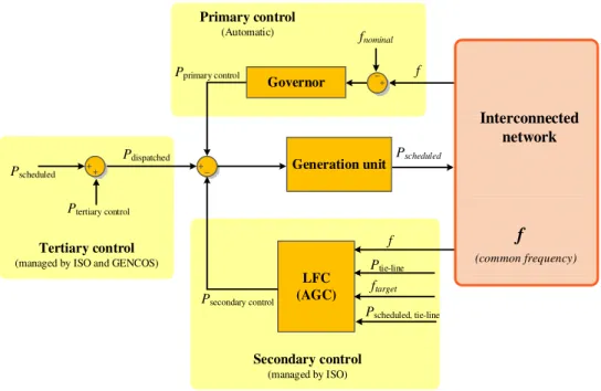
Figure 2.6 shows a general scheme of typical frequency control regulation at different control levels. Usually frequency regulations will consists three different control level with different time responses. Based on the UCTE standard, three control levels are named as primary (droop) control, secondary (supplementary) control and tertiary
20 2. SOA
control level. Usually, all of these three different control action are presented during operation of large-scale interconnected power systems [2.13]-[2.14].
Primary (droop) control. This local automatic control will adjust the active power
generated by each generator units to naturally maintain the balance between consumption and generation [2.13]-[2.16]. At this control level, the generation units which are located in one area with the same frequency will be involved. This control will be performed based on the inertia of each unit and their natural responses of the governors. Generation unit LFC (AGC) Primary control (Automatic) Tertiary control
(managed by ISO and GENCOS)
Secondary control (managed by ISO) f fnominal Pscheduled f Ptie-line ftarget Pdispatched Ptertiary control Pscheduled Interconnected network
f
(common frequency) Governor Pscheduled, tie-line Pprimary control Psecondary controlFigure 2.6. General structure of frequency control based on UCTE regulation.
Secondary (supplementary) control. This control action is higher level control trying
to minimize the steady state error of active power or frequency control deviations. This control level will deliver sufficient reserve powers to control the frequency and tie-line power in their scheduled values.
Tertiary level of control. This level of regulation is mainly related to manual tuning of
dispatched units and unit commitment to act as back-up for secondary control and taking care of optimal operation of generation units and managing severe contingencies of transmission systems.
2.2 Modern power system 21
2.2.4.2
Spinning reserves
In fact, for performing a suitable frequency regulation it is necessary to maintain some amount of power as a reserved capacity. This reserved power can be used for performing the required balance between generation and consumption during the time. In Figure 2.7 different type of reserve capacity which will be used in real practices are presented. These reserves are related to different contingencies with different time frames [2.14]. Usually in literatures, the spinning reserve is known as an unused capacity that could be activated based on the decision of ISO. This reserve could be provided with different devices which have to be synchronized to the grid. They should be able to contribute on changing the active power [2.14].
M aximum
Nat ur al f requency responses
Scheduled pow er
M inimum
0 M W
Energy Synchr onized t ert i ary
cont rol Reser ve Secondary control Reser ve
Pri mary cont rol Reserve Un-used capacit y
Figure 2.7. Participated of reserved unit for different levels of frequency regulation [2.14].
2.2.4.3
Reactive/voltage control services
Normally the controllable generators can control the voltage level at the terminal node with modifying (injecting or absorbing) reactive power. For example, in case of lower value for terminal voltage the amount of reactive power will be increased [2.14]-[2.16]. Different control levels are presented in Figure 2.8. The first control level for terminal voltage regulation in one synchronous generator. This control will be performed by the excitation system. In the hierarchical structure of voltage regulation, the set-points of lower levels will be provided by higher level controls. Usually, the AVR (Automatic Voltage Regulator) in the control loops of synchronous generators is known as lowest
22 2. SOA
level. The second level is known as coordinated Secondary Voltage Regulator (SVC) and the last level will be Tertiary Voltage Control (TVC) which is the highest level.
Generation unit
Central TVC
Primary voltage control
(AVR and exciter)
VT VOpt Vref AVR Optimal programs SCADA Regional SVC
Tertiary voltage control Secondary voltage control
Interconnected network
Pilot node
VP
Figure 2.8. Levels of voltage control.
Primary voltage control. As it was mentioned, this control level is mainly related to
local controller. Local controllers are AVR for synchronous generator or Load Tap Changer (LTC) for some transformers. They can provide a very fast control actions in case of any load variation. Their main responsibility is to keep the voltage bus at its desired values. There are also different type of controllable devices for this purpose. Static voltage compensators is one of this devices that can also participate in this primary control action [2.15].
Secondary voltage control. This control level is a kind of centralized automatic
regulation that can coordinate all the local controllers in their regional voltage zone. This coordination will be performed by changing the local set-points by injecting or absorbing reactive powers. In many different countries, some sort of experience for this secondary control is reported [2.17]-[2.18]. Usually, for this control level, a pilot bus will be defined. This bus will be used to manage the reactive power resources for
2.2 Modern power system 23
providing a suitable voltage profile. This pilot bus voltage will represent the voltage which is related to its neighborhood.
Tertiary voltage control. This control level will be used for more coordination and
better optimization. In this level, different type of optimal power flow programs can be used which will bring more regulation. Usually the time constant of this control level is in the range of 15 minute to hours [2.19]-[2.20].
2.2.4.4
Ancillary services and technologies
For supporting the operation of the power grid, ancillary services will be required. Some of the well-known ancillary services are frequency regulation, load flow control, voltage and reactive power regulation and some security responsibilities which are handled by operator of the systems.
However, as soon as the grid becomes more and more complex, new installations and technologies are needed to provide such functionalities to the system. For example HVDC and FACTS equipments are very important tools in this area [2.21]-[2.22]. In case of HVDC technologies, its main application is for interconnecting the areas with different frequencies. Considering the global integration of renewable energies and exigencies from competitive markets, make necessary to equip the network with several DC interconnections at high voltage level between its areas. For this reason, it is necessary to perform more investigation in VSC-HVDC links as a bi-directional interface between areas based on applying the last technologies in power electronics. Back to Back topology is one of this type of DC interconnections which usually linked for long distance transmission overhead lines or by submarine cable. It mainly used for large amount of power. A much more frequent use of these type of HVDC links can be predicted in near future which will accomplish the requirements in the restructured power system [2.22]-[2.24].
Also, storage technologies depending on their characteristics may aid the integration of renewable sources and they could assist the operation/control of a power system especially in case of ancillary services [2.10]. The main technologies include: pumped hydro [2.24], compressed air storage [2.25], batteries [2.26], super capacitors and super magnetic energy storage (SMES) [2.27].
![Figure 2.7. Participated of reserved unit for different levels of frequency regulation [2.14]](https://thumb-us.123doks.com/thumbv2/123dok_us/1674264.2730313/44.765.172.659.360.643/figure-participated-reserved-unit-different-levels-frequency-regulation.webp)