Available online: https://pen2print.org/index.php/ijr/ P a g e | 42
Increasing Grid Power Transmission Limits Using Pv Statcom With
New Controllers For Day And Night
Jajimoggala Swami Naidu, Mr. A.V.Satyanarayana,Mrs.C.Bharathi
1student,Dept.Of Electrical And Electronics Engineering,Gonna Institute Of Information Technology&Sciences
(Approved By Aicte,New Delhi Affiliated To Jntu,Kakinada) Gonnavanipalem,Paravada(Mandal)
Visakhapatnam -530046
2assistant Professor, Dept.Of Electrical And Electronics Engineering,Gonna Institute Of Information Technology&Sciences
(Approved By Aicte,New Delhi Affiliated To Jntu,Kakinada) Gonnavanipalem,Paravada(Mandal)
Visakhapatnam -530046
3associate Professor, Dept.Of Electrical And Electronics Engineering,Gonna Institute Of Information Technology&Sciences
(Approved By Aicte,New Delhi Affiliated To Jntu,Kakinada) Gonnavanipalem,Paravada(Mandal)
Visakhapatnam -530046 Abstract: This paper presents a novel concept
of utilizing aphotovoltaic (PV) solar farm
inverter as STATCOM, called PV-STATCOM,
for improving stable power transfer limits of
the interconnected transmission system. The
entire inverter rating of the PV solar farm,
which remains dormant during nighttime, is
utilized with voltage and damping controls to
enhance stable power transmission limits.
During daytime, the inverter capacity left after
real power production is used to accomplish
the aforementioned objective. Transient
stability studies are conducted on a realistic
single machine infinite bus power system
having a midpoint located PV-STATCOM
using EMTDC/PSCAD simulation software.
The PV-STATCOM improves the stable
transmission limits substantially in the night
and in the day even while generating large
amounts of real power. Power transfer
increases are
also demonstrated in the same power system
for: 1) two solar farms operating as
STATCOMs and 2) a solar farm as
PV-STATCOM and an inverter-based wind farm
with similar STATCOM controls. This novel
utilization of a PV solar farm asset can thus
improve power transmission limits which
would have otherwise required expensive
additional equipment, such as series/shunt
capacitors or separate flexible ac transmission
Available online: https://pen2print.org/index.php/ijr/ P a g e | 43 Keywords: Maximum Power Point Tracking
(MPPT),Partial Shading, Photovoltaic (PV),
Fuzzy Logic.
I. INTRODUCTION
Flexible AC transmission system
(FACTS) controllers are being increasingly
considered to increase the available power
transfer limits/capacity(ATC) of existing
transmission lines [1]–[4], globally. New
research has been reported on the nighttime
usage of a photovoltaic (PV) solar farm (when
it is normally dormant) where a PV solar farm
is utilized as a STATCOM–a FACTS
controller, for performing voltage control,
thereby improving system performance and
increasing grid connectivity of neighboring
wind farms [5],New voltage control has also
been proposed on a PV solar farm to act as a
STATCOM for improving the power
transmission capacity [7]. Although, [8] and
[9] have proposed voltage-control
functionality with PV systems, none have
utilized the PV system for power transfer limit
improvement. A full converter-based wind
turbine generatorhas recently been provided
with FACTS capabilities for improved
response during faults and fault ride through
capabilities The photoelectric effect was first
noted by French physicist Edmund Becquerel
in 1839. He proposed that certain materials
have property of producing small amounts of
electric current when exposed to sunlight. In
1905, Albert Einstein explained the nature of
light and the photoelectric effect which has
become the basic principle for photovoltaic
technology. In1954 the first photovoltaic
module was built by Bell Laboratories. A
photovoltaic system makes use of one or more
solar panels to convertsolar energy into
electricity. It consists of various components
which include the photovoltaic modules,
mechanical and electrical connections and
mountings and means of modifying the
electrical output.
II. STATIC SYNCHRONOUS
COMPENSATOR(STATCOM)
The STATCOM is a solid-state-based
power converter version of the SVC.
Operating as a shunt-connected SVC, its
capacitive or inductive output currents can be
controlled independently from its terminal AC
bus voltage. Because of the fast-switching
characteristic of power converters, STATCOM
provides much faster response as compared to
the SVC. In addition, in the event of a rapid
change in system voltage, the capacitor voltage
does not change instantaneously; therefore,
STATCOM effectively reacts for the desired
responses. For example, if the system voltage
drops for any reason, there is a tendency for
STATCOM to inject capacitive power to
support the dipped voltages. STATCOM is
Available online: https://pen2print.org/index.php/ijr/ P a g e | 44 compensation does not depend on the common
coupling voltage. Therefore, STATCOM is
very effective during the power system
disturbances. Moreover, much research
confirms several advantages of STATCOM.
These advantages compared to other shunt
compensators include:
• Size, weight, and cost reduction • Equality of lagging and leading output • Precise and continuous reactive power
control with fast response
• Possible active harmonic filter capability
III. PROPOSED WORK
This paper proposes novel voltage control,
together with auxiliary damping control, for a
grid-connected PV solar farm inverter to act as
a STATCOM both during night and day for
increasing transient stability and consequently
the power transmission limit. This technology
of utilizing a PV solar farm as a STATCOM is
called PV-STATCOM. It utilizes the entire
solar farm inverter capacity in the night and
the remainder inverter capacity after real
power generation during the day, both of
which remain unused in conventional solar
farm operation.
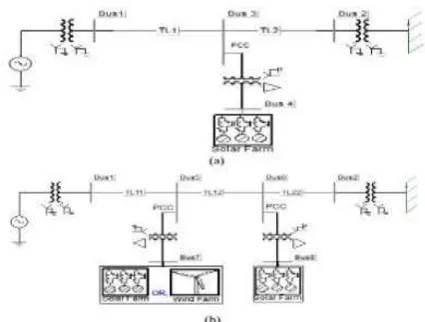
Fig. 1. Single line diagram of (a) Study
system I with single solar farm (DG) and (b)
Study System II with a solar farm (DG) and
a solar/wind farm (DG).
The synchronous generator is represented by a
detailed sixth order model and a DC1A-type
exciter. The transmission-line segments TL1,
TL2, TL11, TL12, and TL22, shown in Fig. 1,
are represented by lumped pi-circuits. The PV
solar DG, as shown in Fig. 2, is modeled as an
equivalent voltage-source inverter along with a
controlled current source as the dc source
which follows the - characteristics of PV
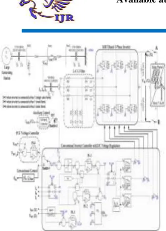
Available online: https://pen2print.org/index.php/ijr/ P a g e | 45 Fig. 2. Complete DG (solar/wind) system
model with damping controller and PCC
voltage control system.
The wind DG is likewise modeled as an
equivalent voltagesource inverter. In the solar
DG, dc power is provided by the solar panels,
whereas in the full-converter-based wind DG,
dc power comes out of a controlled AC–DC
rectifier connected to the PMSG wind turbines,
depicted as “wind Turbine-Generator-Rectifier
(T-GR).” The dc power produced by each DG
is fed into the dc bus of the corresponding
inverter, as illustrated in Fig. 2.
A maximum power point tracking (MPPT)
algorithm based on an incremental
conductance algorithm [12] is used to operate
the solar DGs at its maximum power point all
of the time and is integrated with the inverter
controller [11]. The wind DG is also assumed
to operate at its maximum power point, since
this proposed control utilizes only the inverter
capacity left after the maximum power point
operation of the solar DG and wind DG.
For PV-STATCOM operation during
nighttime, the solar panels are disconnected
from the inverter and a small amount of real
power is drawn from the grid to charge the dc
capacitor. The voltage-source inverter in each
DG is composed of six insulated- gate bipolar
transistors (IGBTs) and associated snubber
circuits as shown in Fig.2. An appropriately
large dc capacitor of size 200 Farad is selected
to reduce the dc side ripple [13].
A novel auxiliary damping controller is added
to the PV control system and shown in in Fig.
2.(b). This controller utilizes line current
magnitude as the controlsignal. The output of
this controller is added with the signal
Id_ref.At first the base case generator
operating power level is selected for
performing the damping control design
studies. This power level is considered equal
to the transient stability limit of the system
with the solar farm being disconnected at
night. At this operating power level, if a three
phase fault occurs at Bus 1, the generator
power oscillations decay with a damping ratio
of 5%. The solar farm is now connected and
Available online: https://pen2print.org/index.php/ijr/ P a g e | 46 In this study, the solar DG is assumed to
operate with its conventional reactive power
controller the DG operates at near unity power
factor. For the nighttime operation of solar
DG, the DC sources (solar arrays) are
disconnected and the solar DG inverter is
connected to the grid using appropriate
controllers, as described below. Power
transmission limits are now determined for the
following four cases. The maximum stable
power output from the generator Pg is 731
MW when the solar DG is simply sitting idle
during night and is disconnected from the
network. This power flow level is chosen to be
the base value against which the improvements
in power flow with different proposed
controllers are compared and illustrated. The
damping controller utilizes the full rating of
the DG inverter at night to provide controlled
reactive power Qsolar and effectively damps
the generator rotor mode oscillations. The
voltages at generator bus Vg and at PCC bus
Vrms(PCC). This reflects the losses in the
inverter IGBT switches, transformer and filter
resistances caused by the flow of real current
from the grid into the solar farm inverter to
charge the DC link capacitor and maintain its
voltage constant while operating the PV
inverter as STATCOM with the damping
controller (or even with voltage controller).
During nighttime, the reference DC Link
voltage Vmpp_ref is chosen around the typical
daytime rated maximum power point (MPP)
voltage
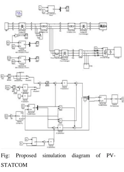
IV.SIMULATION AND RESULTS
Simulink model
Fig: Proposed simulation diagram of PV-STATCOM
SIMULATION RESULTS:
Fig. 4. Maximum nighttime power transfer (731 MW) from the generator
Available online: https://pen2print.org/index.php/ijr/ P a g e | 47
Fig4 (a): Real power at receiving end.
Fig4 (b) :Real power at sending end.
Fig4:Maximum nighttime power transfer (850 MW) from the generator with
solar DG using the damping controller
Fig4: Real power at receiving end.
Fig5:Maximum daytime power transfer (719 MW) from the generator with
solar DG generating 91-MW real power
Fig5 (a): Real power at receiving end
Fig4 (b): Real power at sending end
Maximum nighttime power transfer (899 MW)
from the generator while the solar DG uses a
Available online: https://pen2print.org/index.php/ijr/ P a g e | 48 5.CONCLUSION
Solar farms are idle during nights. A
novel patent-pending control paradigm of PV
solar farms is presented where they can
operate during the night as a STATCOM with
full inverter capacity and during the day with
inverter capacity remaining after real power
generation, for providing significant
improvements in the power transfer limits of
transmission systems [31], [32]. This new
control of PV solar system as STATCOM is
called PV-STATCOM.
The effectiveness of the proposed controls is
demonstrated on two study SMIB systems:
System I has one 100-MW PV-STATCOM
and System II has one 100-MW
STATCOM and another 100-MW
PV-STATCOM or 100-MW wind farm controlled
as STATCOM. Three different types of
STATCOM controls are proposed for the PV
solar DG and inverter-based wind DG. These
are pure voltage control, pure damping control,
and a combination of voltage control and
damping control.
The following conclusions are made: 1) In
study system I, the power transfer can be
increased by 168 MW during nighttime and by
142 MW in daytime even when the solar DG is
generating a high amount of real power. 2) In
Study System II, the transmission capacity in
the night can be increased substantially by 229
MW if no DG is producing real power. During
nighttime and daytime, the power transfer can
be increased substantially by 200 MW, even
when the DGs are generating high real power.
This study thus makes a strong case for
relaxing the present grid codes to allow
selected inverter-based renewable generators
(solar and wind) to exercise damping control,
thereby increasing much needed power
transmission capability. Such novel controls
on PV solar DGs (and inverter-based wind
DGs) will potentially reduce the need for
investments in additional expensive devices,
such as series/shunt capacitors and FACTS.
The PV-STATCOM operation opens up a new
opportunity for PV solar DGs to earn revenues
in the nighttime and daytime in addition to that
from the sale of real power during the day.
This will, of course, require appropriate
agreements between the regulators, network
utilities, solar farm developers, and inverter
Available online: https://pen2print.org/index.php/ijr/ P a g e | 49 REFERENCES
[1] R. M. Mathur and R. K. Varma,
Thyristor-Based FACTS Controllers for
Electrical Transmission Systems. Hoboken,
NJ, USA: Wiley/IEEE, 2002.
[2] S. A. Rahman, R. K. Varma, and
W. Litzenberger, “Bibliography of FACTS
applications for grid integration of wind and
PV solar power systems: 1995–2010, IEEE
working group report,” presented at the IEEE
Power Energy Soc. Gen. Meeting, Detroit, MI,
USA, Jul. 2011.
[3] Y. Xiao, Y. H. Song, C.-C. Liu, and
Y. Z. Sun, “Available transfer capability enhancement using FACTS devices,” IEEE
Trans. Power Syst., vol. 18, no. 1, pp. 305–
312, Feb. 2003.
[4] Cross Texas Transmission, Salt
fork to gray project. 2014. [Online]. Available:
http://www.crosstexas.com/SFWind.htm
[5] R. K. Varma, V. Khadkikar, and R.
Seethapathy, “Nighttime application of PV
solar farm as STATCOM to regulate grid
voltage,” IEEE Trans. Energy Converse., vol.
24, no. 4, pp. 983–985, Dec. 2009.
[6] R. K. Varma and V. Khadkikar,
“Utilization of solar farm inverter as STATCOM,” U.S. Provisional Patent, Sep. 15,
2009
. [7] R. K. Varma, S. A. Rahman, and
R. Seethapathy, “Novel control of grid
connected photovoltaic (PV) solar farm for
improving transient stability and transmission
limits both during night and day,” in Proc.
World Energy Conf., Montreal, QC, Canada,
2010, pp. 1–6.
[8] R. A. Walling and K. Clark, “Grid
support functions implemented in utility-scale
PV systems,” in Proc. IEEE Power Energy
Soc, Transm.Distrib. Conf. Expo., 2010, pp.
1–5.
[9] F. L. Albuquerque, A. J. Moraes, G.
C. Guimaraes, S. M. R. Sanhueza, and A. R.
Vaz, “Photovoltaic solar system connected to
the electric power grid operating as active
power generator and reactive power
compensator,” Solar Energy, vol. 84, no. 7, pp.
1310–1317, Jul. 2010.
[10] A. Beekmann, J. Marques, E.
Quitmann, and S. Wachtel, “Wind energy
converters with FACTS Capabilities for
optimized integration of wind power into trans.
and dist. systems,” in Proc. CIGRE, Calgary,
AB, Canada, 2009.
[11] S. A. Rahman and R. K. Varma,
“PSCAD/EMTDC model of a 3-phase grid connected photovoltaic solar system,” in Proc.
43rd North Amer. Power Symp., Boston, MA,
USA, 2011, pp. 1–5.
[12] K. H. Hussein, I. Muta, T.
Hoshino, and M. Osakada, “Maximum
photovoltaic power tracking: an algorithm for
Available online: https://pen2print.org/index.php/ijr/ P a g e | 50 Proc. Inst. Elect. Eng., Gen., Transm. Distrib.,
vol. 142, no. 1, pp. 59–64, Jan. 1995.
[13] K. Chatterjee, B. G. Fernandes,
and G. K. Dubey, “An instantaneous reactive
volt–ampere compensator and harmonic
suppressor system,” IEEE Trans. Power
Electron., vol. 14, no. 2, pp. 381–392, Mar.