Abstract- An efficient method for wireless power transfer would also enable advances in such diverse areas as embedded computing, mobile computing, sensor networks, and micro robotics. The need to minimize energy consumption is often the main design driver in applications where devices need to operate without tethered. Energy consumption often restricts functionality in such applications. The work depicted in this paper is inspired by potential application of magnetic resonant coupling as a means for WPT from a source coil to a single load Several experiments regarding this technique need to carry out for a better output and the day is not far when the need for wires will get obsolete
1. Introduction
The problem with many of today’s electronic devices, such as cell phones, laptop computers and personal digital organizers, is that despite their probability and ability to communicate wirelessly, these devices still require regular charging – usually by plugging into a wall outlet. The ability to provide power for these and other electric devices wirelessly would greatly increase their portability and accessibility for the public. An efficient method for wireless power transfer would also enable advances in such diverse areas as embossed computing, mobile computing, sensor networks and micro robotics. The need to minimize the energy consumption is often the main design driver in applications where devices need to operate without ethered. Energy consumption often restricts or severely limits functionally in such applications. The work described in this paper is motivated by potential application of magnetic resonant coupling
as a means for wireless power transfer from a source coil to a single load. Through simple experimental setups and corresponding circuit .models, we address issues that are involved in applying the basic mechanism to a single receiver.
2. Theoretical Model
Our experimental realization of the scheme consists of three coils that are tuned at the same frequency. An oscillating circuit is connected with a source coil S. Coil S is coupled resonant inductively to an intermediate Coil Q; which is in turn coupled resonant inductively to a load carrying Coil R. The coils are made of an electrically conducting copper pipe of cross-sectional radius a wound into a helix of single turn, radius r.
Q S
AC
C1
R
C2
Load
Figure.1 Theoretical Model of the System
Then a radio frequency oscillating signal is passed through coil S, it generates an oscillating magnetic field, perpendicular to the coil S. The intermediate coil Q is placed near to the Coil S, which is tuned at the same frequency through the inductance of the
coil and a resonating capacitorC1. The coil Q being in the area of the magnetic field generated by coil S, receives power. The coil Q turn generates its own oscillating magnetic field without any resistive load. The advantage of using this coil is that it is completely separated from the source internal Mr. Shrikant Joshi1Roll No: TMT17069 Dr. Hari KumarNaidu2
TulasiramjiGaikwad-Patil College ofEngineering Dean of ElectricalDepartmen & Technology,Nagpur
TulasiramjiGaikwad-Patil College ofEngineering
resistance. This increases the Q-factor, allowing greater power to be mediated. In other words, the coil Q becomes the source of the system.
The load coil R, tuned at the same resonant frequency, receives the power through the magnetic field generated by the intermediate coil Q.
3. Power Transfer Model of Wireless Power Transfer System
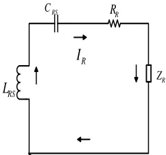
The equivalent circuit diagram of power transfer model is given in figure-2. The power transfer occurs from coil S to coil R. The power loss in coil Q is neglected here, since the coil Q has a very small resistance.
R Z R
R
R C R
L
R I
Figure.3 Equivalent circuits for theoretical model
R
I
R R
R
Z
RS
L
RS
C
Figure .3 Equivalent circuits for Figure .2
Where,
T
Z = Source impedance of transmitter circuit,
T
C = Total capacitance of the LC tank in transmitter
circuit,
T
L = Total impedance of the LC tank in transmitter
circuit,
T
R = Source resistance of transmitter circuit,
T
I = Total current of transmitter circuit,
R
C = Total capacitance of LC tank in the receiver
circuit,
R
L = Total impedance of LC tank in the receiver
circuit,
R
R = Total resistance of
receiver circuit,
R
Z = Load impedance
of receiver circuit,
R
I = Total current of
receiver circuit,
Vs
T
Z RT
T
C LT
T
I
Vs T
Z RT
T I
TS C
TS L
V1 Vs
T
Z
R
TT
I
TS
C
RS
C
= Equivalent series capacitance of CR,
TS
C
= Equivalent series capacitance of CT,
RS
L
= Equivalent series inductance of LR,
TS
L
= Equivalent series inductance of LT.
V2 RS
C
RS L R I R Z R RFigure.4 The equivalent circuit diagram for Figure .3 with voltage drop due to mutual impedance
Where, Now ) C 1 L ( j R Z Z TS TS T S
T
) C 1 L ( j R Z Z RS RS R L
R
S S S R j Z
L L L R j Z
Mesh Equation for the transmitter circuit,
0 I Z V
VS 1 T T
T 1 S T Z V V I
T R M S T Z I Z V I
Mesh Equation for the receiver circuit,
0 I Z V2 R R
R T M R R Z I Z Z V
I
2 R R M S M R Z I Z V Z
I ( )
S M R M R
TZ Z I Z V
Z
( 2 )
2 M R T S M R Z Z Z V Z I 2 M R T s R R R T T Z Z Z V Z I Z Z I
The delivering power by the transmitter circuit,
} Re{ }
Re{ * *
1 VSIT VS IT
P
} Re{ * 2 * * * 1 M R T S R S Z Z Z V Z V P
The receiving power by the receiver load,
L R T L R
TI Z I I R
I
) )(
( 2 * * 2*
*
2
M R T M R T
L S M M
Z Z Z Z Z Z
R V Z Z P
4. Experimental set-up and design
In the practical experiment, 4 different set-ups are made.
An 18V transformer is used as the power supply. This transformer is connected with the rectifier circuit.
An oscillator circuit is used as the transmitter.
Two copper coil with capacitor connected is used as the receiver.
A LED is used as the load which is connected with the receiver.
Figure.5 Implementation of wireless power transfer system
The total implementation of the project is given below–
The 18V transformer with rectifier circuit is connected to the transmitter or oscillator circuit.
The RF chokes present in the transmitter circuit creates a magnetic field.
The receiver coil which constitutes of an inductor and capacitor is placed at a distance from the transmitter circuit.
The LC circuit of the receiver coil produces resonance with the magnetic field generated from the source and transmitter circuit.
When the switching is performed, the LED we have used as a load lit up to a maximum distance of 60 centimeter with voltage measured 2.2 volts.
Performance and Analysis
Efficiency and Evaluation of Power Losses Measurements have been taken providing 30V with resonant frequency 1.5 MHz across the transmitter and without the intermediate coil.
1) A 3 watt bulb lit up at its full strength at a
distance of 17 centimeter with voltage measured 15 volts.
2) A 3 watt bulb lit up to a maximum distance of 41 centimeter with voltage measured 10 volts.
3) A LED lit up to a maximum distance of 70 centimeter with voltage measured 2.2 volts.
Table .1 Theoretical and practical comparison for 3 watt bulb (Without intermediate coil)
Distanc e
Output
Voltage(Theoretical )
Output Voltage(Practical )
17cm 17 volts 15 volts
25cm 15 volts 13.1 volts
34cm 12 volts 11 volts
41cm 11 volts 10 volts
Graphical analysis of theoretical and practical comparison of output voltage for 3 watt bulb (without intermediate coil) is given below:
Figure 6. Theoretical and practical comparison for 3 watt bulb (without intermediate coil)Here the black line represents the theoretical and blue line represents the experimental data
LED (without intermediate coil):
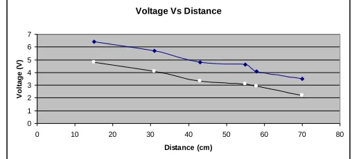
Table.2 Theoretical and practical comparison for LED. (Without intermediate coil)
Distance
Output
Voltage(Theoretical)
Output Voltage (Practical)
31cm 5.7 volts 4.1 volts
43cm 4.8 volts 3.3 volts
58cm 4.1 volts 2.9 volts
70cm 3.5 volts 2.2 volts
Graphical analysis of theoretical and practical comparison of output voltage for LED (without intermediate coil) is given below:
Figure:7. Theoretical and practical comparison for LED (without intermediate coil) Here the blue line represents the theoretical and black line represents the experimental data. Measurements have been taken with intermediate coil placed in between transmitter and receiver at a distance 12 cm apart from the transmitter.
1) A 3 watt bulb lit up at its full strength at a distance of 34 centimeter with voltage measured 15 volts.
2) A 3 watt bulb lit up to a maximum distance of 61 centimeter with voltage measured 10 volts.
Voltage Vs Distance
0 5 10 15 20
0 5 10 15 20 25 30 35 40 45
Distance (cm)
V
ol
ta
ge
(
V
)
Voltage Vs Distance
0 1 2 3 4 5 6 7
0 10 20 30 40 50 60 70 80
Distance (cm)
V
ol
ta
ge
(
V
3) A LED lit up to a maximum distance of 91 centimeter with voltage measured 2.2 volts.
4) Voltage measured at a distance 5.90 meters and the voltage measured 6 milli-volts.3 watt bulb (with intermediate coil):
Table 8.3 Theoretical and practical comparison for 3 watt bulb
(With intermediate coil)
Distance Output Voltage (Theoretical)
Output Voltage (Practical)
34cm 18 volts 15 volts
45cm 16.5 volts 14 volts
54cm 13 volts 12.4 volts
61cm 11 volts 10 volts
Graphical analysis of theoretical and practical comparison of output voltage for 3 watt bulb (with intermediate coil) is given below:
Figure.8 Theoretical and practical comparison for 3
represents the theoretical and pink line represents the experimental data.
LED (with intermediate coil):
Table.4 Theoretical and practical comparison for LED (With intermediate coil)
Distance
Output Voltage
(Theoretical)
Output Voltage(Practical)
51cm 4.5 volts 3.7 volts
64cm 4.1 volts 3.4 volts
78cm 3.6 volts 2.9 volts
91cm 2.7 volts 2.2 volts
Graphical analysis of theoretical and practical comparison of output voltage for LED (with intermediate coil) is given below:
Figure.9 Theoretical and practical comparison for LED (with intermediate coil)
Here the blue line represents the theoretical and pink line represents the experimental data.
For the experimental setup with a single receiver,
Voltage Vs Distance
0 5 10 15 20 25
0 10 20 30 40 50 60 70
Distance (cm)
V
ol
ta
ge
(
V
)
Voltage Vs Distance
0 1 2 3 4 5 6
0 10 20 30 40 50 60 70 80 90 100
Distance (cm)
V
ol
ta
ge
(
V
transmitter is 21.2V. The output rms voltage across a 192-Ω resistive load 34cm away from the coil is 10.6V.
The difference between supplied and received power for the system with a single receiver is accounted for power dissipation in resistances. 50% of the power that leaves the terminals of the actual source (ideal source in series with internal resistance) is delivered to the load resistance.
Calculation
Resonant frequency, LC
f
2 1
Here,
L = 100µH
C = 60nF
= 3.1416
Resonant frequency,
nF H
f
60 100
1416 . 3 2
1
= 64.974 kHz
6. Analysis
The dominant loss occurs in the internal source resistance. This loss occurs whenever a source delivers power to a load, whatever through wires or through a wireless power transfer method. The high internal resistance of the oscillator, used here only for concept demonstration, can be significantly reduced by using a more practical power source. Approximately half remaining power is delivered to
the load resistance, with dissipation in the source coil resistance, the largest loss beyond the actual source terminals. By using an intermediate coil close to the source coil increases the Q-factor to a great extent. The intermediate coil takes up most of the power from the source coil and delivers to the load coil. The Q-factor increases as the intermediate coil does not have source internal resistance in it. Thus the power transfer efficiency and the power transfer range increases significantly.
7. Summary
Apart from losses due to non-ideal characteristics of the inductor and capacitor, radiation loss and ohmic loss; the total power transmitted might not be received because of the loading effect of the receiver which causes the system to “de-tune” from resonance and weakening the coupling factor. Also wave attenuation occurs when it passes through a lossy dielectric medium (free space, air). If the effect of the losses can be minimized then the efficiency of the overall system can be improved to desired levels. The theoretical model and circuit implementation of the wireless power transfer system was designed based on the concept of magnetic resonant coupling. Various optimization factors were also considered while designing the whole system. Due to generalized approach, presented wireless power transfer system can be optimized for new design constraints or for different applications.
8. Conclusion
agreement with the theoretical models. We have described and demonstrated that magnetic resonant coupling can be used to deliver power wirelessly from a source coil to a load coil with an intermediate coil placed between the source and load coil and with capacitors at the coil terminals providing a simple means to match resonant frequencies for the coils. This mechanism is a potentially robust means for delivering wireless power to a receiver from a source coil
9. References
1. Tesla N., Colorado Springs Notes 1899-1900 (Nikola Tesla Museum, Belgrade, 1978)
2. Fernandez J. M., Borras J. A., U.S. patent 6,184,651 (2001).
3. Wikipedia.org for information on wireless power transmission history. http://www.wikipedia.org.
4. Esser A. and Skundelny H.C., “A New Approach to Power Supplies for Robots”, IEEE Transactions on Industry Applications, Vol. 21, No. 5, pp. 872-875, September 1991.
5. Hirai J., Kim T.-W., Kawamura A., “Wireless transmission of power and information and information for cableless linear motor drive”, IEEE Trans. Power Electron. 15, 21(2000).
6. The Science Magazine, article titled by “Portable devices get power wirelessly”