Volume 2006, Article ID 89849, Pages1–12 DOI 10.1155/ASP/2006/89849
Differential Space-Time Coding Scheme Using Star Quadrature
Amplitude Modulation Method
Xiangbin Yu,1DaZhuan Xu,1, 2and Guangguo Bi2
1Information and Communication Engineering Postdoctoral Research Station, Nanjing University of Aeronautics and Astronautics,
Nanjing 210016, China
2National Mobile Communications Research Laboratory, Southeast University, Nanjing 210096, China
Received 5 July 2005; Revised 11 January 2006; Accepted 13 January 2006
Recommended for Publication by Richard Barton
Differential space-time coding (DSTC) has received much interest as it obviates the requirement of the channel state information at the receiver while maintaining the desired properties of space-time coding techniques. In this paper, by introducing star quadrature amplitude modulation (star QAM) method, two kinds of multiple amplitudes DSTC schemes are proposed. One is based on differential unitary space-time coding (DUSTC) scheme, and the other is based on differential orthogonal space-time coding (DOSTC) scheme. Corresponding bit-error-rate (BER) performance and coding-gain analysis are given, respectively. The proposed schemes can avoid the performance loss of conventional DSTC schemes based on phase-shift keying (PSK) modulation in high spectrum efficiency via multiple amplitudes modulation. Compared with conventional PSK-based DSTC schemes, the developed schemes have higher spectrum efficiency via carrying information not only on phases but also on amplitudes, and have higher coding gain. Moreover, the first scheme can implement low-complexity differential modulation and different code rates and be applied to any number of transmit antennas; while the second scheme has simple decoder and high code rate in the case of 3 and 4 antennas. The simulation results show that our schemes have lower BER when compared with conventional DUSTC and DOSTC schemes.
Copyright © 2006 Hindawi Publishing Corporation. All rights reserved.
1. INTRODUCTION
With the fast development of modern communication tech-nique, the demand for reliable high data rate transmission in fading channel is increased significantly, which stimulate much interest in multiple antennas communication, espe-cially, space-time coding schemes [1–3]. However, the eff ec-tiveness of most space-time coding schemes depends on per-fect channel estimation at the receiver, which is difficult to implement in practice due to rapid changes in time-varying channel, or due to the overhead needed to estimate a large number of parameters such as in a MIMO system [4]. Thus, the differential modulation scheme becomes an attractive al-ternative.
With differential detection, channel state information (CSI) is not required either at the transmitter or at the re-ceiver. Hochwald and Marzetta [5] proposed an effective modulation scheme to improve system capacity (i.e., uni-tary space-time modulation) with noncoherent detection for multiple antennas in fading channel, and then unitary space-time coding. Subsequently, Hochwald and Sweldens [6] and
Hughes [7] independently came up with differential
all from the unitary constellation and corresponding en-coded matrix has unity-amplitude. As a result, when spec-trum efficiency gets higher, the minimum product distance between the two encoded matrices decreases as the mini-mum distance between symbols decrease, which will bring about the obvious reduce of coding gain and the loss of sys-tem performance. These conclusions can also be achieved from Table I in [7] and Table I in [11]. Considering that the minimum distance between multiple levels QAM symbols is larger than the corresponding PSK symbols’ distance [12], we adopt the star QAM method to map MPSK-based code matrices. On one hand, we can utilize both the phase and amplitude to carry information to improve the spectrum ef-ficiency further; on the other hand, by star QAM method, constellation matrices are no longer limited in unity constel-lation and they have more freedom, the minimum produced distance is increased accordingly. Thus we can improve the performance of pervious code matrix and avoid the perfor-mance degradation in high spectrum efficiency. Although a differential space-time block code scheme based on square-QAM is proposed in [13], the scheme is limited in existing STBC structure and suits square STBC only, and has high-complexity differential modulation. Motivated by the rea-son above, on the basis of analyzing differential orthogo-nal space-time coding (DOSTC) scheme and differential uni-tary space-time code (DUSTC) scheme, we develop the two multiple-amplitude differential space-time coding schemes by the star QAM method, and analyze corresponding perfor-mance over Rayleigh fading channel. Meanwhile, we give dif-ferential space-time coding scheme for nonsquare code ma-trix and derive the calculation formulas of the coding gain in detail. Compared with existing DUSTC and DOSTC, the schemes have lower bit error rate (BER) and higher coding gain.
2. SYSTEM MODEL AND STAR QAM
In this section, we consider a wireless communication sys-tem withK antennas at the transmitter,N antennas at the receiver, and the system operating over a flat Rayleigh fad-ing channel. Given thatH = {hkn}isK×N, fading channel
matrix, where hkn denotes the complex channel gain from
transmit antennakto receive antennan. The channel gains are modeled as samples of independent complex Gaussian random variables with zero-mean and variance 0.5 per real dimension, and the channel state information is unknown at the receiver. LetGibe the code matrix withK×Ktransmitted
at time blocki, then at the receiver, the received signal matrix Xican be expressed by
Xi=γGiH+Zi, (1)
whereZiisK×Ncomplex Gaussian noise matrix, whose
el-ements are independent, identically distributed (i.i.d) com-plex Gaussian random variables with zero-mean and unit-variance. Let the code matrix index beiand time epoch index within the code matrix bet. So at the receiver, the received
Tx
gi,t
gi,t
gi,t,K
h
h1N
h21
h2N
hK1
hKN
Rx
xi,t,1
xi,t,2
xi,t,N
Zi,t,1
Zi,t,2
Zi,t,N
Figure1: Structure diagram of a MIMO wireless system.
signal for receive antennan(n=1, 2,. . .,N) can be written by
xi,t,n=γ K
k=1
gi,t,khk,n+zi,t,n, (2)
where the coded symbols from code matrix are normalized to obeyE{K
k=1|gi,t,k|2} =1, thus it can ensure thatγis the
expected signal-to-noise ratio (SNR).{zi,t,n}are elements of
noise matrixZi. The structure diagram of a MIMO wireless
communication system withKtransmit antennas andN re-ceive antennas is illustrated inFigure 1.
As we know, quadrature amplitude modulation (QAM) is a bandwidth efficient transmission method for digital sig-nals. Compared with MPSK modulation, the MQAM has stronger ability against inference in fading channel, its M constellation points are not limited in unit amplitude, but have multiple amplitudes [14, 15]. Thus they have more freedom and higher minimum distance among constellation points. For 4 bits symbol, there are usually two constellation mapping methods, that is, square mapping and star map-ping. 16 square QAM requires coherent detection, whereas 16 star QAM can adopt differential detection. Due to the ro-bustness of the differential detection scheme in fading chan-nels, star QAM has received much attention for mobile radio applications [15]. For this reason, we employ the star QAM scheme to improve the performance of existing differential space-time codes.Figure 2illustrates the signal constellations ofM-level star QAM, it consists of two rings. The two rings both correspond to M/2-PSK constellation, but they have different amplitudes, that is, a0 anda1 in Figure 2; where a1 = βa0,βis the amplitude ratio. For simplicity,M = 16 is employed inFigure 2.
3. MULTIPLE AMPLITUDES DIFFERENTIAL UNITARY
SPACE-TIME CODING
a0 a1
Figure2: 16 star QAMs constellation.
the transmitter, the information is differentially encoded at time blockias follows:
Gi=VdiGi−1, (3)
where Gi and Gi−1 are the transmitted matrices at i and i−1, respectively; and initial code matrixG0=IK×K, which
does not carry any information. Vdi is a unitary
informa-tion matrix. According to [6], for a transmission rate ofR bits/channel use, it requires a constellation withP=2RK
dif-ferent signals, each signal is aK×Kunitary matrixVpfrom
a constellationΥofP such distinct unitary matrices. Here, the data to be transmitted are assumed to be an integer data sequenced1,d2,. . ., withdp ∈ {0, 1,. . .,P−1}. Clearly, all
the transmitted matricesGiwill be unitary. While for [7], the
information matrixViis from the set of all possible
infor-mationΓ,ΓisK×Kunitary matrix group. For anyV ∈Γ, the equationV VH =VHV =I
K×K holds; the superscriptH
denotes conjugate transpose of matrix. Thus the transmitted signal matrix satisfies the equationGi = ViGi−1with initial matrixG0=D,Dis aK×Kunitary matrix [7].
At the receiver, we assume that the channel gains remain constant at two consecutive time blocks, then according to (1), the received matrices at time blocki−1 andiare give by
Xi−1=γGi−1H+Zi−1,Xi=γGiH+Zi, respectively.
(4)
From (3), (4) can be changed as follows:
Xi=γGiH+Zi
=γVdiGi−1H+Zi
=Vdi
Xi−1−Zi−1+Zi
=VdiXi−1+Zi−VdiZi−1
=VdiXi−1+
√
2Zi,
(5)
whereZiis aK×Nnoise matrix. Consider thatZiandZi−1 are both complex Gaussian matrices and their elements are
zero-mean and unit-variance, andZiis a complex Gaussian
matrix, and its elements are alsoi.i.dcomplex Gaussian ran-dom variables with zero-mean and unit-variance.
From the above-mentioned analysis and [6], we can ob-tain the decision variable for transmitted datadiby
employ-ing maximum likelihood (ML) detector as follows:
di=arg minp=0,...,P−1 Xi−VpXi−1 2
=arg minp=0,...,P−1trXi−VpXi−1Xi−VpXi−1H
, (6)
where the operator tr(·) denotes the matrix trace. Considering
trXi−VpXi−1Xi−VpXi−1H
=trXiXiH
−2 RetrVpXi−1XiH
+ trVpXi−1XiH−1VpH
=trXiXiH
−2 RetrXi−1XiHVp
+ trXi−1XiH−1VpHVp
.
(7)
Then (6) can be equivalent to
di=arg maxp∈0,...,P−1Re
trXi−1XiHVp
. (8)
Based on the above analysis, the ML detector for differential modulation can be interpreted as follows: the block code re-ceived at timei−1 is used as an estimate of the channel, and this estimate is used to do a coherent detection of the block code at timei. Similarly, the block code received at timeiis also the channel estimate for decoding blocki+ 1.
To simplify the transmission scheme and the constel-lation designs, [6] also gives simple group code structure. Namely, the set {V0,. . .,VP−1} forms a cyclic group, and Vp=V1P(p=0, 1,. . .,P;V1is a diagonal generator matrix) becomes a diagonal matrix, this design criterion is essentially the same as the scheme in [7]. Thus according to [7], the de-cision value for the information matrixVican be achieved by
employing ML detector as follows:
Vi=arg minVi∈Φ Xi−ViXi−1
2
=arg minVi∈ΦtrXi−ViXi−1Xi−ViXi−1H
=arg maxVi∈ΦRetrXi−1XiHVi
,
(9)
where constellationΦ is the set formed by{V0,. . .,VP−1}; as shown in [6,7],Φhas group structure, and the optimal codes are achieved by maximizing the coding gain inΦ. The coding gain (as defined in [11]) is
Λcg= min
Fu=FqK×Λp
Fu,Fq
whereΛp(Fu−Fq)= {det((Fu−Fq)(Fu,Fq)H)}1/Kis the
prod-uct distance between two code matricesFuandFq, det(·)
rep-resenting determinant operator.
For a constellation constructed from multiple data sym-bols, a good metric to judge the performance is the square of the minimum distance between two points in the con-stellation. If the distance is bigger, then the performance is better. Similarly, for the constellation constructed by code matrices, the coding gain (i.e., above Λcg) is a good
met-ric to judge the performance of corresponding constellation in terms of error probability analysis in [6,7]. For unitary space-time coding, however, when spectrum efficiency gets higher, the performance will become worse due to the lower coding gain, which can be seen in Table I in [7]. Consider-ing that the matrices in unitary space-time codes group has unity energy (i.e., single amplitude), which can be thought as MPSK constellation, whereas star MQAM scheme has bet-ter performance than corresponding MPSK under the same spectrum efficiency, we adopt the star QAM scheme to design superior DUSTC. By using the star QAM method, we can carry information by means of not only the phase but also the amplitude of the code matrix. The spectral efficiency is thus improved accordingly. Moreover, the constellation ma-trices will not be limited in unity-energy, thus they have dif-ferent amplitudes, and minimum product distance will be improved accordingly. As a result, the performance degra-dation is overcome effectively in high spectrum efficiency. Specific encoding and decoding schemes are designed as fol-lows.
At the transmitter, the input bit streams are divided into each data block including log2Mbits, namely theith data block corresponds to data bits{bim, m = 1, 2,. . ., log2M}. The first bitbi1is used to decide the amplitude of differential unitary space-time code matrix to transmit, other log2 M-1 bits{bim, m=2,. . ., log2M}perform conventional diff er-ential unitary space-time modulation, and the modulation will adopt group code which takes values in the M/2-PSK rather than MPSK. Then, we design corresponding multiple-amplitude differential encoding scheme in terms of the fol-lowing equations:
Gi=GiGi=GiViGi−1, Gi=ViGi−1, (11)
where|G0| =ρ0,G0=IK×K[6] orG0=D[7],|Gi|denotes
the amplitude ofGi. It may chooseρ0orρ1(ρ0andρ1are the amplitudes of inner and outer unitary matrix constellation, which are similar to the amplitudes of inner and outer ring of star QAM scheme, respectively; andρ1=βρ0), which de-pends on the value ofbi1. Ifbi1=0, the amplitude ofGiis the
same as that of the previous transmitted code matrixGi−1; if bi1 =1, the amplitude ofGiis different from the amplitude
ofGi−1, that is, if|Gi−1| =ρ0,|Gi| =ρ1; and if|Gi−1| =ρ1,
|Gi| =ρ0.
At the receiver, we employ the method similar to star QAM demodulation to demodulate the received signals. After multiple amplitudes modulation, the received signal
matrices at time blocksi−1 andiare changed accordingly as follows:
Xi−1=γGi−1H+Zi−1=γGi−1Gi−1H+Zi−1, (12) Xi=γGiH+Zi=γGiViGi−1H+Zi. (13)
Based on the above received signal matrices, we can make corresponding differential detection to achieve the decision variables ofbim(i.e.,bimm=1,. . ., log2M). Firstly, the phase detection is performed in terms of (9), namely conventional DUSTC demodulation method can be applied. Thus, corre-sponding decision bit variablesbim(m= 2,. . ., log2M) are obtained. Then, we employ the detection method in [14] to perform amplitude detection. Namely, the decision variable
bi1for amplitude bit is obtained according to the equivalent amplitude ratio
λa=
Kt=1
N
n=1xi,t,n2
K
t=1
N
n=1xi−1,t,n2
= Xi
Xi−1 ,
(14)
whereXiis the Frobenius norm ofXi.
LetξLandξH be two amplitude decision thresholds as
shown in [14], these decision thresholds are assumed to be related according toξH=1/ξL, and they satisfy the following
conditions:
β−1< ξL<1, 1< ξH< β. (15)
Ifλafalls inside two decision thresholds, that is, ifλasatisfies
ξL < λa < ξH, the amplitude decision variablebi1 =0. The converse holds, ifλafalls outside of two decision thresholds,
that is, ifλasatisfiesλa < ξLorλa < ξH,bi1=1. The above threshold values can be optimized so that corresponding sys-tem BER is minimized under a given SNR.
Based on the above analysis and property of unitary space-time codes, the proposed multiple amplitudes DUSTC scheme (MDUSTC) can implement full diversity and differ-ent rates; and it can be applied to any number of antennas. Besides, the scheme has low-complexity differential modu-lation due to the diagonal matrix of USTC, but it requires group structure and has exponential decoding complexity. Fortunately, [16] gives fast ML decoding algorithms for con-ventional USTC scheme. The algorithms exploit the constel-lation structures and are polynomial rather than exponential, in the ratesRandK.
4. MULTIPLE AMPLITUDES DIFFERENTIAL
ORTHOGONAL SPACE-TIME CODING
4.1. Code matrix
higher coding gain while it does not need a group structure in general.
Let{Ul}Ll=1 and{Wl}Ll=1 be a set of 2Lmatrices of size K×Kwhich satisfy the following conditions:
UlUlH=IK×K, WlWlH=IK×K, ∀l,
UlUsH= −UsUlH, WlWsH= −WsWlH, ∀l=s,
UlWsH=WsUlH, ∀l,s,
(16)
whereIK×Kdenotes identity matrix. Then{Ul}and{Wl}are
said to constitute an amicable orthogonal design of orderK inLvariables [10,11]. The detailed design process for{Ul}
and{Wl}withK = 2, 4, 8 which meet with the conditions
in (16) can be seen in [10]. By introducing the amicable or-thogonal design, we can design corresponding code matrix.
Let{cil}Ll=1be a block ofLsymbols to be transmitted at a timei, and the symbolcil (l=1,. . .,L) is from PSK
con-stellationΩ. Thus thecil can be expressed bycil =cilR+ jcIil,
wherecRil andcIil denote the real and imaginary parts of cil,
respectively. By defining theCias
Ci=
L
l=1
UlcRil+jWlcilI
√
L. (17)
Then we have
CiCiH= L l=1cil2
L
IK×K=IK×K. (18)
ThusCiis a unitary code matrix.
4.2. Differential encoding and decoding schemes
In this subsection, the differential encoding and decoding schemes for orthogonal space-time coding are firstly ana-lyzed. Then multiple amplitudes DOSTC scheme using star QAM method is given. At the transmitter, we consider the case ofK×Ksquare code matrices at first. According to [10], we have suchK×Kmatrices{Ul,Wl}forK=2, 4, and 8. The
ith block to be transmitted is a differential encoding matrix GiwithK×K. At the start of the transmission, the
transmit-ter sends aK×K identity matrix as initial code matrixG0 (i.e.,G0 = IK×K), which does not carry information. Then
the information matrixCias defined by (17) is differentially
encoded in terms of Gi = CiGi−1. FromG0 = IK×K,Ci is
unitary matrix, andGi = CiGi−1, we can testify thatGiis a
unitary matrix. Thus the information matrixCican be
de-coded fromGiGHi−1 =CiGi−1GHi−1 = Ciif the code matrices
GiandGi−1are observable at the receiver.
At the receiver, the received matrices at timesiandi−1 are written byXi= √γGiH+ZiandXi−1= √γGi−1H+Zi−1, respectively.
According to (9), we can obtain the ML detector for{cil}
by
cil L
l=1=arg max{cil},cil∈ΩRe
trXi−1XiHCi
. (19)
From (17), (19) can be further transformed to ML detector for single symbolcilby
cil=arg maxcil∈ΩRe
trXi−1XiHUl
cRil
+ RetrjXi−1XiHWl
cl il
=arg maxcil∈ΩRetrXi−1XiHUl
cRil
+ Imtr−Xi−1XiHWl
cI il,
(20)
where Re(·) and Im(·) denote real part operator and imag-inary part operator, respectively. Equation (20) can be changed into the detection of real part and imaginary part in parallel as follows:
cRil =arg maxcil∈ΩRe
trXi−1XiHUl
cilR,
cIil=arg maxcil∈ΩIm
−trXi−1XiHWl
cilI.
(21)
Namely the detector has a decoupled form, one scalar detec-tor for each of the symbols {cil}. Thus compared with the
detection method of other differential codes, the detection method of the proposed scheme has a much lower computa-tional complexity.
From the above-mentioned analysis, we can see that dif-ferential orthogonal space-time coding scheme is still limited in MPSK modulation, and its performance will degrade un-der high spectrum efficiency. It is because corresponding de crease of minimum product distance between code matrices brings about the reduction of coding gain, and these conclu-sions can be drawn form Table I in [11]. Motivated by the reason analyzed in Section 3, we adopt the star QAM con-stellation method to map the code matrices to improve the performance of conventional DOSTC scheme. Specific en-coding and deen-coding schemes are designed as follows.
At the transmitter, the input bits stream are divided into each data block including (1 +Llog2M) bits, namely, bim
(m = 1, 2,. . ., 1 +Llog2M) represents the ith data block, whereLis the number of symbols to be transmitted in the information code matrix. The first bitbi1is used to decide the amplitude of differential orthogonal space-time code ma-trix; other bits firstly perform MPSK modulation, and are mapped to corresponding data symbols. Then these symbols are used to construct the information code matrixCiin terms
of (17). Afterwards, the following differential modulation is performed:
Gi=GiGi=GiCiGi−1, Gi=CiGi−1, G0=IK×K.
After performing multiple amplitudes modulation, the re-ceived code matrix need corresponding changes as shown in (13). Namely,
Xi=γGiGiH+Zi=γGiCiGi−1H+Zi. (23)
At the receiver, we make phase and amplitude detec-tion for the received code matrices, respectively. At first, we employ conventional DOSTC decoding method to perform phase detection, namely, by utilizing (20) and (21) to get ML detector of{cil, l=1, 2,. . .,L}. Then via demapping in
ac-cordance, the decision bits{bim,m=2,. . ., 1 +Llog2M}are
obtained. For amplitude detection, we can adopt the decision method inSection 3. Based on this method, the amplitude decision bitbi1is finally achieved.
4.3. Nonsquare matrix differential space-time coding and code rate
The scheme presented in Section 4.2is valid for K = 2, 4, and 8 transmit antennas, and corresponding code matrix is square matrix. Now we consider the scheme in the case of K = 3, 5, 6, and 7 transmit antennas, where the code ma-trix will not be square mama-trix. This is also an open problem which needs to be solved in future work in [13]. For simplic-ity of analysis, we only focus on the 3 transmit antennas case; similar analysis can be extended to other three cases. For 3 transmit antennas, we transmit the first three columns of the differential code matrix of 4 transmit antennas to perform corresponding data transmission, which can be realized by a transform matrix as follows:
G(3)i =G
(4)
i T, (24)
whereG(3)i andG
(4)
i denote the transmitted differential code
matrices for the case of 3 transmit antennas and 4 transmit antennas, respectively.G(4)i is 4×4 square matrix, andG(3)i
is 4×3 nonsquare matrix;T =
1 0 0
0 1 0 0 0 1 0 0 0
is a 4×3 transform matrix.
Based on the above transform and (22), we can imple-ment the data transmission of 3 transmit antennas case by transmittingG(4)i T. According to (23), the corresponding
re-ceived signal matrix at timeiis written by
Xi=γG(3)i G
(4)
i TH+Zi=γG(3)i G
(4)
i H+Zi, (25)
whereH =THis the equivalent channel gain matrix. After equivalent transform, theT can be absorbed in the channel gain matrix. Considering that THT = I
3×3, thenHHH = HHTHTH =HHH. Thus the same diversity performances
are obtained. Moreover, after the above transform, we can make use of the previous 4-antenna analysis method to detect the received data for 3-antenna systems at the receiver, and the system performance is not affected.
In addition, our scheme is based on the amicable orthog-onal design, so the scheme has the same code rate of the code proposed in [10]. In the case of 2 transmit antennas;
the code rate of our scheme is unity-rate, which is the same as the scheme proposed in [8]. Moreover, in the case of 3 or 4 transmit antennas, our scheme has a code rate of 3/4, which is higher than the scheme developed in [9]; and the same as the schemes proposed in [11,13], but the structure of code matrix is simpler than that in [13]. Besides, our scheme has lower computational complexity. However, we also no-tice that the scheme is only applied to no more than 8 trans-mit antennas due to the litrans-mitation of amicable orthogonal design, and in the case of more than 5 transmit antennas, it has only 1/2-code rate, which will affect high date rate trans-mission to some extent and bring about the decrease of data rate.
5. BIT-ERROR-RATE PERFORMANCE
From the theory analysis in Sections3and4, we can see that the phase and amplitude detection processes are indepen-dent, thus we can evaluate the average bit error rate (BER) via calculating the BER’s of phase detection and amplitude detection separately. Namely,
Pb=
log2M−1Pb-phase+Pb-amplitude
log2M for MDUSTC, (26)
Pb=
Llog2MPb-phase+Pb-amplitude
1 +Llog2M for MDOSTC, (27)
wherePb-phaseandPb-amplitudeare the BER’s of phase detection and amplitude detection, respectively. These equations are a weighted sum of the BER of phase detection and amplitude detection.
For amplitude detection, the bit error probability is writ-ten by
Pb-amplitude
=
Pb,am(HL) +Pb,am(HH) +Pb,am(LH) +Pb,am(LL)
4 ,
(28)
where Pb,am(HL) denotes the amplitude detection error
probability for amplitude bits from outer constellation to inner constellation; other three items (i.e., Pb,am(HH),
Pb,am(LH),Pb,am(LL)) can be explained in similar manner.
These four terms may be further changed as
Pb,am(HL)=Pρ1,ρ0
λa> ξL
−Pρ1,ρ0
λa> ξH
,
Pb,am(LH)=Pρ0,ρ1
λa> ξL
−Pρ0,ρ1
λa> ξH
,
Pb,am(HH)=Pρ1,ρ1
λa> ξH
+ 1−Pρ1,ρ1
λa> ξL
,
Pb,am(LL)=Pρ0,ρ0
λa> ξH
+ 1−Pρ0,ρ0
λa> ξL
wherePρ1,ρ0(λa > ξL) denotes the amplitude detection error
probability for amplitude bits from outer constellation to in-ner constellation whenλa > ξL; similar explanation can be
applied for other seven items.
For phase detection, the bit error probability is written by
Pb-phase=
Pb,ph(HL) +Pb,ph(HH) +Pb,ph(LH) +Pb,ph(LL)
4 ,
(30)
wherePb,ph(HL) denotes the phase detection error bit
proba-bility for phase signal (which consists of corresponding phase bits) from outer constellation to inner constellation; other three items can be explained in similar way.
Consider that detailed BER derivation is more complex, and needs a plenty of mathematic calculation and theoretical analysis. Namely, it needs more space for BER calculation. Here, we only give some calculation steps to briefly review the derivation. For simplicity, the following only provides these steps with the example of 2Tx and 1Rx MDOSTC scheme.
(1) Calculate the phase detection error bit probability Pb-phasein terms of (30).
From (30), we need to compute Pb,ph(HL),Pb,ph(HH),
Pb,ph(LH), andPb,ph(LL), respectively. Considering that these
four cases occur with equal probability, we can choose an ar-bitrary case for first calculation. Without loss of generality, Pb,ph(HL) is firstly considered. By a series of calculation and
using some related results from [12], we can derive its ap-proximate parameter expression on amplitude pair (ρ1,ρ0) (which corresponds to phase signal from outer constellation to inner constellation). Then employing similar calculation method, and substituting this amplitude pair with (ρ1,ρ1), (ρ0,ρ1), and (ρ0,ρ0) in corresponding places, respectively, we can evaluate corresponding phase detection error bit proba-bilitiesPb,ph(HH),Pb,ph(LH), andPb,ph(LL), respectively.
Ac-cording to (30), we can obtain thePb-phasebased on the eval-uatedPb,ph(HL),Pb,ph(HH),Pb,ph(LH), andPb,ph(LL).
(2) Evaluate the amplitude detection error bit probability Pb-amplitudein terms of (28) and (29).
From (28), we need to calculatePb,am(HL),Pb,am(HH),
Pb,am(LH), andPb,am(LL), respectively. Without loss of
gen-erality, we choosePb,am(HL) as first calculation. According
to (29),Pρ1,ρ0(λa > ξL) andPρ1,ρ0(λa > ξH) need to be
cal-culated. Here, we first evaluate the amplitude detection error probability for amplitude bits from outer constellation to in-ner constellation whenλa> ξL, that is,Pρ1,ρ0(λa> ξL) is firstly
evaluated. According to (14) and employing the appendices results of [12], we can obtain the value ofPρ1,ρ0(λa> ξL) via
a series of calculation and derivation. Using similar calcula-tion method and substitutingξLwithξH, we can calculate
the value ofPρ1,ρ0(λa > ξH). Then changing the amplitude
pair (ρ1,ρ0) into (ρ1,ρ1), (ρ0,ρ1), and (ρ0,ρ0) in correspond-ing places, respectively, and utilizcorrespond-ing the above calculation method, we can evaluatePρ1,ρ1(λa > ξL),Pρ0,ρ1(λa > ξL), and
Pρ0,ρ0(λa > ξL), respectively. Thus according to the evaluated
three values, we can obtainPρ1,ρ1(λa > ξH),Pρ0,ρ1(λa > ξH)
andPρ0,ρ0(λa > ξH) via substitutingξLwithξH accordingly.
Based on the above results and (29), the values forPb,am(HL),
Pb,am(HH),Pb,am(LH), andPb,am(LL) can be calculated,
re-spectively. As a result, we will obtain the amplitude detection error bit probabilityPb-amplitudeaccording to (28).
(3) Compute the average bit error rate for MDOSTC scheme.
Based on the obtained Pb-phase andPb-amplitude, we can compute the average bit error rate for MDOSTC in terms of (27). Similar method can be applied to evaluate the average bit error rate for MDUSTC in terms of (26). Due to high cal-culation complexity, we no longer provide the average BER expression here; the detailed BER derivation will appear in another paper of ours for space considerations.
6. CODING-GAIN ANALYSIS
As mentioned inSection 3, for the constellation constructed by code matrices, the coding gain (i.e.,Λcgin (10)) is a good
metric to judge the performance of corresponding constel-lation. By maximizing the coding gain, the optimal group codes are obtained in [6,7]. LetFuandFqbe the information
matrices (as defined in (17)) constructed from the data sym-bols sets{fu1,. . .,fuL}and{fq1,. . .,fqL}, respectively, where
symbols{ful}and{fql}are both from constellationΩ. Let
F=Fu−Fq, according to (17),Fcan be changed to
F=
L
l=1
Ul
fR ul−fqlR
+jWl
fl ul−fqll
√
L . (31)
Then according to (18), we have
FFH=1
L
L
l=1
fR
ul−fqlR
2 +fl
ul−fqll
2
Ik×K
=1
L
L
l=1
ful−fql2
Ik×K.
(32)
So the product distance betweenFuandFqcan be written by
Λp
Fu,Fq
=detFu,Fq
Fu,Fq
H1/K
=detFFH1/K
=
det
1 L
L
l=1
ful−fql2
IK×K
1/K
=1
L
L
l=1
|ful−fql|2
.
(33)
ForFu=Fq, (33) is minimized when{ful}and{fql}differ in
just one symbol, while the other corresponding symbols are same, namely, the minimal value corresponds to the minimal distance between constellation points fromΩ. Hence, we can evaluate the coding gain in terms of (10) and (33) as follows:
Λcg= min ful,fml∈Ω
K L
ful−fql2
=
K L
d2 min=
K L
2 sin
π M
2
,
where dmin is the minimal distance between constellation points ofM-level PSK constellationΩ. The above equation is used to calculate the coding gain of MPSK-based conven-tional DOSTC scheme. In the following, we will give an-other formula to evaluate the coding gain of the proposed MDOSTC scheme.
In this paper, we assume that the amplitude bits are trans-mitted with equal probability, andρ1=β 2/(1 +β2) so that (ρ2
1+ρ20)/2=1, whereρ0 =ρ1/β, andβis assumed to be 2, which is the optimum amplitude ratio from [14,15], for this, we will give detailed explanation in simulation. According to (10), the coding gain of MDOSTC scheme can be defined as follows:
Λcg=min Fu=FqK×Λp
Fu,Fq
=min
Fu=FqK×Λp
F
uFu,FqFq
, (35)
where|Fu|and|Fq|are the amplitudes of matricesFuandFq,
respectively; which chooseρ0orρ1.
When matricesFuandFqare from the same constellation
(i.e., inner constellation or outer constellation),|Fu| = |Fq|.
Without loss of generality, let they be from inner constella-tion, then we have
Λp
Fu,Fq
=detρ0Fu−ρ0Fq
ρ0Fu−ρ0Fu
H1/K
=ρ2 0
detFu−Fq
Fu−Fq
H1/K
=ρ2 0Λp
Fu,Fq
.
(36)
From (34) and (36), (35) can be changed to
Λcg0=
K L
!
2ρ0sin
π M 2 "2 . (37)
Note: for MDOSTC scheme using M-level star QAM method, the symbols in matricesFuandFq are from
M/2-level PSK constellation.
Similarly, we can evaluate the coding gain whenFu and
Fqare from outer constellation:
Λcgl=
K L
!
2ρ1sin
π M 2 "2 . (38)
When matricesFu andFq are from different
constella-tion, namely, one is from inner constellaconstella-tion, the other is from outer constellation. Without loss of generality, let the former be from outer constellation, and the latter from inner constellation, thenFu−Fqis changed as follows:
Fu−Fq
=ρ1Fu−ρ0Fq
=√1
L L l=1 Ul
ρ1fulR−ρ0fqlR
+jWl
ρ1fulI−ρ0fqlI
.
(39)
So according to (39) and (18), we have the following equa-tion:
Fu−Fq
Fu−Fq
H = 1 L L l=1
ρ1fulR−ρ0fqlR
2
+ρ1fulI−ρ0fqlI
2 IK×K
= 1 L L l=1
ρ1ful−ρ0fql2
IK×K.
(40)
Hence,
Λp(Fu,Fq)=
detFu−Fq
Fu−Fq
H1/K
= 1 L L l=1
ρ1ful−ρ0fql
2 .
(41)
Considering that{ful}and{fql}are from PSK constellation,
we can assume that ful=ejθuland fql=ejθql. Then we have ρ1ful−ρ0fql2
=ρ1ejθul−ρ0ejθql2
=ρ1ejθul−ρ0ejθql
ρ1e−jθul−ρ0e−jθql
=ρ2
1+ρ20−2ρ1ρ0cos
θul−θql
≥ρ2
1+ρ20−2ρ1ρ0=
ρ1−ρ0
2 ,
(42)
where cos(θul−θql)≤1 is utilized. So the minimum value of
|ρ1ful−ρ0fql|2is (ρ1−ρ2)2.
Based on the above analysis, using (41) and (42), we can evaluate the coding gain as follows:
Λcg2=min
Fu=FqK×Λp
Fu,Fq
=K×1
L×L
ρ1−ρ0
2
=Kρ1−ρ0
2 .
(43)
Similarly, we can calculate the coding gain whenFu andFq
are from inner constellation and outer constellation, respec-tively:
Λcg3=min
Fu=FqK×Λp
Fu,Fq
=Kρ0−ρ1
2
. (44)
Λcg=
Λcg0+Λcgl+Λcg2+Λcg3
4
=
#K
L
2ρ0sin
π M 2
2
+KL2ρ1sin
π M 2
2
+ 2Kρ1−ρ0
2$
4 .
(45)
Table 1: Comparison of coding gain of DOSTC scheme and MDOSTC scheme.
ConstellationΦ Coding gain (K=2,L=2)
Coding gain (K=3,L=3)
Coding gain (K=4,L=3)
10 PSK 0.38197 0.38197 0.5093
16 PSK 0.1522 0.1522 0.203
22 PSK 0.081 0.081 0.108
32 PSK 0.0384 0.0384 0.05124
16 star QAM 0.6928 0.8928 1.1905
32 star QAM 0.4771 0.6771 0.9028
Based on (34) and (45), we compare the coding gain of the multiple amplitudes DOSTC scheme and conven-tional DOSTC scheme under different spectrum efficiency in
Table 1. FromTable 1, we can see that the coding gain of the proposed MDOSTC scheme is higher than that of DOSTC scheme under same spectrum efficiency, while the coding gain of DOSTC scheme is higher than the corresponding dif-ferential unitary space-time coding scheme [11]. Hence our scheme has superior performance. Moreover, with the in-crease of spectrum efficiency, that is, whenMbecomes big-ger, the coding gain of conventional DOSTC scheme will crease quickly; whereas for our scheme, the coding gain de-creases slowly. So our scheme can avoid the extra perfor-mance degradation of conventional DOSTC scheme effec-tively in high spectrum efficiency.
For the presented multiple amplitudes DUSTC (MDUSTC) scheme, we can employ the above-mentioned analysis method and related computation formula from [7] to evaluate the coding gain, detailed deriving process is no longer given due to the repeated work. Similarly, the same conclusion can be reached. Namely, our MDUSTC scheme has higher coding gain than the corresponding DUSTC scheme under the same spectrum efficiency. Thus the performance of our MDUSTC scheme is superior to the corresponding DUSTC scheme, which will also be testified by the following simulation.
7. SIMULATION RESULTS
In this section, to test the validity of the proposed scheme, we provide the simulation results in Rayleigh fading chan-nel. The channel is assumed to be quasistatic flat fading. In simulation, the differential unitary space-time coding and
100
10−1
10−2
10−3
10−4
8 12 16 20 24 28
SNR (dB)
BER
DUSTC2T DOSTC2T
MDUSTC2T MDOSTC2T
Figure 3: BER against SNR for different differential space-time codes with 2-transmit antennas.
differential orthogonal space-time coding are applied for the purpose of comparison with the same spectrum efficiency. Every data frame includes 960 information bits, and Gray mapping of the bits to symbol is employed. The numbers of transmit antennas are 2, 3, and 4, and the number of receive antennas is set as 1 for simplicity. Besides, in the case of per-forming amplitude detection, we adopt the parameters given in [14,15], such asβ = 2,ξH = 1.47,ξL = 0.68, and so
forth. The simulation results are obtained from 106 Monte-Carlo simulation run, and they are illustrated in Figures3–6, respectively.
Figure 3shows the BER versus SNR for different
100
10−1
10−2
10−3
10−4
6 10 14 18 22
SNR (dB)
BER
DUSTC2T8P MDUSTC2T8Q
Figure 4: BER against SNR for DUSTC and MDUSTC with 2-transmit antennas.
scheme also obtains about 3 dB gains over the DUSTC at BER = 10−2. A similar conclusion can be drawn from
Figure 4. InFigure 4, we compare the performance of the proposed MDUSTC scheme with the DUSTC scheme de-veloped in [7], our scheme uses the 8 star QAM method, while the DUSTC employs the 8 PSK modulation; where the generator matrix of the optimal unitary group codes
diag(exp(2π j/8), exp(−2π j/8)), invdiag(−1, 1)[7] is used for the DUSTC, and theρ1diag(exp(2π j/4), exp(−2π j/4)), invdiag(−1, 1)∪ρ2diag(exp(2π j/4), exp(−2π j/4)), invdiag (−1, 1)is used for the MDUSTC. Similarly, our scheme still outperforms the corresponding DUSTC scheme; it achieves 2 dB gains at the BER of 10−3. So after adopting mul-tiple amplitudes modulation, our developed schemes are both superior to corresponding differential space-time cod-ing schemes, and our MDUSTC scheme slightly outperforms DOSTC. The reason for these is that our schemes can obtain higher coding gain via using star QAM method, which is con-sistent with the theoretical analysis inSection 6. Besides, the proposed MDOSTC scheme performs better than another proposed MDUSTC scheme, which accords with the conclu-sions drawn in [11], that is, DOSTC outperforms DUSTC.
In the above work, we employ the parameters in [14,15]. In fact, these decision threshold (i.e.,ξH,ξL) and amplitude
ratioβcan be chosen and optimized in terms of the criterion that the system BER is minimized at given SNR. Using this criterion, the optimumβfor differential detection of single antenna system in Rayleigh fading channel was found to be approximately 2; and the threshold values were searched and calculated, they were 1.47 and 0.68, respectively [15]. Simi-larly, according to this criterion, [14] gave the optimized val-ues aboutβandξH(ξL=1/ξH) under Rician fading channel
by computer search, that is,β=2,ξH =1.47. In our work,
we also optimize these decision thresholds for multiple am-plitudes differential space-time code scheme via computer
100
10−1
10−2
10−3
10−4
10−5
10 12 14 16 18 20 22 24 26 28 30 SNR (dB)
SER
(sy
m
bol
er
ror
ra
te
)
DOSTC2T10P MDOSTC2T
DOSTC4T10P MDOSTC4T
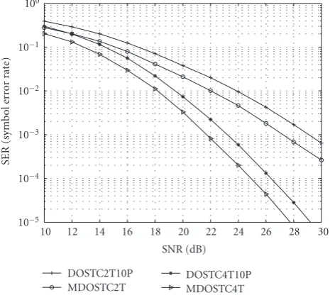
Figure 5: SER against SNR for DOSTC and MDOSTC with 2-transmit antennas and 4-2-transmit antennas.
search. Firstly, the optimized amplitude ratio is produced in terms of the above criterion by fixingξH = 1.47, then
us-ing this optimized amplitude ratio, the threshold values are reevaluated and optimized so that the system BER is mini-mized, the detailed optimized process can be seen in [14,15]. Of course, we may also obtain the optimum combination of (β,ξH) via computer search based on the above optimum
cri-terion. As a result, the produced optimized value is almost identical to the optimized values provided by [14,15], so we still adopt the above parameters in following simulation.
100
10−1
10−2
10−3
10−4
10−5
10 15 20 25 30
SNR (dB)
SER
(sy
m
bol
er
ror
ra
te
)
DOSTC3T10P MDOSTC3T
Figure 6: SER against SNR for DOSTC and MDOSTC with 3-transmit antennas.
the performance comparison of differential unitary space-time coding accordingly, since searching the optimal cyclic group code under the same spectrum efficiency is too diffi -cult. In terms of the analysis method outlined inSection 4.3, the 3-transmit antennas performance comparison is pro-vided inFigure 6. In this figure, the 16 star QAM method and 10 PSK are adopted. It is shown inFigure 6that our scheme is still better than differential orthogonal space-time coding; it can obtain about 2 dB gains. Based on the above conclusions, our simulation results make an agreement with the previous theoretical analysis.
8. CONCLUSIONS
On the basis of differential unitary space-time coding and differential orthogonal space-time coding, by using the star QAM method, two kinds of multiple amplitudes differential space-time coding schemes are presented in this paper; one is multiple amplitudes differential unitary space-time cod-ing; the other is multiple amplitudes differential orthogo-nal space-time coding. The two schemes can avoid the per-formance degradation of conventional DSTC scheme based on PSK modulation due to the decrease of minimum pro-duce distance in high spectrum efficiency. The developed MDUSTC scheme can be applied to any number of antennas, and implement different data rates, and low-complexity dif-ferential modulation due to the application of cyclic group codes. It has higher coding gain than existing differential unitary space-time coding. For the developed MDOSTC scheme, it has higher coding gain than existing differential orthogonal space-time coding schemes. Moreover, it has sim-pler decoder and can obtain higher code rate in the case of three or four transmit antennas. The simulation results in fading channel also show that our schemes have lower BER than the corresponding differential unitary space-time codes
and differential orthogonal space-time codes under the same SNR.
ACKNOWLEDGMENTS
This work is supported by the Chinese Jiangsu Planned Projects for Postdoctoral Research Funds and by China Post-doctoral Science Foundation under Grant no. 2005038242. The authors would like to thank the two anonymous review-ers for their useful comments and constructive suggestions throughout the course of reviewing this paper, and thank Prof. Richard Barton for his helpful suggestions.
REFERENCES
[1] N. Al-Dhahir, C. Fragouli, A. Stamoulis, W. Younis, and R. Calderbank, “Space-time processing for broadband wireless access,”IEEE Communications Magazine, vol. 40, no. 9, pp. 136–142, 2002.
[2] V. Tarokh, N. Seshadri, and A. R. Calderbank, “Space-time codes for high data rate wireless communication: performance criterion and code construction,”IEEE Transactions on Infor-mation Theory, vol. 44, no. 2, pp. 744–765, 1998.
[3] V. Tarokh, H. Jafarkhani, and A. R. Calderbank, “Space-time block codes from orthogonal designs,”IEEE Transactions on Information Theory, vol. 45, no. 5, pp. 1456–1467, 1999. [4] C. Gao and A. M. Haimovich, “BER analysis of MPSK
space-time block codes with differential detection,”IEEE Communi-cations Letters, vol. 7, no. 7, pp. 314–316, 2003.
[5] B. M. Hochwald and T. L. Marzetta, “Unitary space-time mod-ulation for multiple-antenna communications in Rayleigh flat fading,” IEEE Transactions on Information Theory, vol. 46, no. 2, pp. 543–564, 2000.
[6] B. M. Hochwald and W. Sweldens, “Differential unitary space-time modulation,” IEEE Transactions on Communications, vol. 48, no. 12, pp. 2041–2052, 2000.
[7] B. L. Hughes, “Differential space-time modulation,” IEEE Transactions on Information Theory, vol. 46, no. 7, pp. 2567– 2578, 2000.
[8] V. Tarokh and H. Jafarkhani, “A differential detection scheme for transmit diversity,”IEEE Journal on Selected Areas in Com-munications, vol. 18, no. 7, pp. 1169–1174, 2000.
[9] H. Jafarkhani and V. Tarokh, “Multiple transmit antenna dif-ferential detection from generalized orthogonal designs,”IEEE Transactions on Information Theory, vol. 47, no. 6, pp. 2626– 2631, 2001.
[10] G. Ganesan and P. Stoica, “Space-time block codes: a maxi-mum SNR approach,”IEEE Transactions on Information The-ory, vol. 47, no. 4, pp. 1650–1656, 2001.
[11] G. Ganesan and P. Stoica, “Differential modulation using space-time block codes,”IEEE Signal Processing Letters, vol. 9, no. 2, pp. 57–60, 2002.
[12] J. G. Proakis, Digital Communications, McGraw-Hill, New York, 4th edition, 2001.
[13] M. Tao and R. S. Cheng, “Differential space-time block codes,” inProceedings of IEEE Global Telecommunications Conference (GLOBECOM ’01), vol. 2, pp. 1098–1102, San Antonio, Tex, USA, November 2001.
fading,”IEEE Transactions on Vehicular Technology, vol. 46, no. 4, pp. 923–932, 1997.
[15] Y. C. Chow, A. R. Nix, and J. P. McGeehan, “Analysis of 16-APSK modulation in AWGN and Rayleigh fading channel,” Electronics Letters, vol. 28, no. 17, pp. 1608–1610, 1992. [16] A. Shokrollahi, B. Hassibi, B. M. Hochwald, and W. Sweldens,
“Representation theory for high-rate multiple-antenna code design,” IEEE Transactions on Information Theory, vol. 47, no. 6, pp. 2235–2367, 2001.
Xiangbin Yureceived the M.S. degree in communication and information systems from Hohai University, Nanjing, China, in 2001; and his Ph.D. in communication and information systems in 2004 from the Na-tional Mobile Communications Research Laboratory at Southeast University, China. Now he is working as a Postdoctoral Re-searcher in Information and Communica-tion Engineering Postdoctoral Research
Sta-tion at Nanjing University of Aeronautics and Astronautics, Nan-jing, China. His research interests include multicarrier digital com-munication, space-time coding, adaptive modulation, and digital signal processing in modern communications.
DaZhuan Xuwas graduated from Nanjing Institute of Technology, Nanjing, China, in 1983. He received the M.S. degree and the Ph.D. in communication and information systems from Nanjing University of Aero-nautics and AstroAero-nautics in 1986 and 2001, respectively. He is now a Full Professor in the College of Information Science and Technology, Nanjing University of Aero-nautics and AstroAero-nautics, Nanjing, China.
He is a Senior Member of China Institute of Electronics (CIE). His research interests include digital communications, software radio, coding theory, and medical signal processing.
Guangguo Biwas graduated from Nanjing Institute of Technology, Nanjing, China, in 1960. He is now a Professor at the National Mobile Communication Research Labora-tory, the Department of Radio Engineering, Southeast University, Nanjing, China. He is a Fellow and a Member of the Board of Di-rector of the China Institute of Communi-cations, and a Senior Member of the IEEE. His research interests include digital