Blind I/Q Signal Separation-Based Solutions
for Receiver Signal Processing
Mikko Valkama
Institute of Communications Engineering, Tampere University of Technology, P.O. Box 553, 33101 Tampere, Finland Email:[email protected]
Markku Renfors
Institute of Communications Engineering, Tampere University of Technology, P.O. Box 553, 33101 Tampere, Finland Email:[email protected]
Visa Koivunen
Signal Processing Laboratory, Helsinki University of Technology, P.O. Box 3000, 02015 HUT, Finland Email:[email protected]
Received 5 February 2004; Revised 14 October 2004
This paper introduces some novel digital signal processing (DSP)-based approaches to some of the most fundamental tasks of radio receivers, namely, channel equalization, carrier synchronization, and I/Q mismatch compensation. The leading principle is to show that all these problems can be solved blindly (i.e., without training signals) by forcing the I and Q components of the observed data as independent as possible. Blind signal separation (BSS) is then introduced as an efficient tool to carry out these tasks, and simulation examples are used to illustrate the performance of the proposed approaches. The main application area of the presented carrier synchronization and I/Q mismatch compensation techniques is in direct-conversion type receivers, while the proposed channel equalization principles basically apply to any radio architecture.
Keywords and phrases:radio communications, complex-valued (I/Q) signals and systems, I/Q mismatch, carrier synchronization and tracking, channel equalization, blind signal separation.
1. INTRODUCTION
In order to increase the receiver flexibility while also empha-sizing the receiver integrability and other implementation-related aspects, the design of radio receivers is no longer dominated by the traditional superheterodyne architec-ture. Instead, alternative receiver structures, like the direct-conversion [1,2] and low-IF [1,3,4] architectures, are re-ceiving more and more interest. The analog front-end of these types of receivers is partially based on complex or I/Q signal processing [5,6,7]. More specifically, the frequency translation from radio frequencies (RF) closer to baseband is carried out using I/Q downconversion. Since, in theory, the I/Q downconversion corresponds to a pure frequency translation, the fundamental image signal problem is basi-cally avoided during the downconversion. In this manner, the
This is an open access article distributed under the Creative Commons Attribution License, which permits unrestricted use, distribution, and reproduction in any medium, provided the original work is properly cited.
requirements for RF image rejection filtering are greatly re-laxed in practice [1,2,3,4].
However, with higher-order modulations, such as 16- or 64-QAM, the distortion due to self-image cannot be ne-glected and again some kind of compensation is needed [11, 12, 13]. This is also one of the topics of this paper. The idea in this paper is first to show that I/Q mismatch causes crosstalk between the I and Q components. Then this crosstalk or mixing of the I and Q is removed using blind signal separation (BSS) techniques [14,15,16]. Compared to the other available solutions in the literature [12, 13], the proposed concept is especially attractive since no known training signals are needed. Also the ability to follow possi-ble time dependencies in the mismatch parameters (due to, e.g., temperature changes) is another highly desirable fea-ture.
Another challenging practical problem in radio commu-nications is carrier synchronization [6]. In practice, it is un-likely that the frequency and relative phase of the receiver local oscillators exactly match those of the received carrier. In case of linear modulations, a constant phase offset intro-duces a constant rotation to the received constellation which needs to be compensated unless differential phase modula-tion is used. Even a bigger problem is caused by errors or offsets in frequency which basically result in time-varying ro-tation of the constellation. This is obviously unacceptable for most modulation types and needs to be efficiently compen-sated for. In this paper, the carrier offsets are shown to re-sult intime-varying leakage between the I and Q, and car-rier tracking is implemented with adaptive signal separa-tion methods. Furthermore, when combined with the previ-ous I/Q mismatch compensation, a single BSS stage can ac-complish both tasks jointly in a blind manner. These kinds of approaches have not been considered in the literature so far.
In addition to the above front-end-related issues, the dis-tortion due to transmission channel [6,15] is inevitable in any radio receiver and needs to be addressed with care. As will be shown, a general bandpass channel can be viewed to cause frequency-selectivecrosstalk between the transmit-ted I and Q data. Based on this, convolutive mixture (or FIR-MIMO) separation techniques working on the observed I and Q signals are applied to implement channel equaliza-tion.
The organization of the paper is as follows. The direct-conversion receiver architecture is shortly reviewed in
Section 2, and the basic principles of blind signal separation techniques are presented inSection 3. InSection 4, appropri-ate MIMO signal models for both I/Q mismatch and carrier offsets are derived, and a signal separation-based approach for blindly compensating these impairments is proposed. Ex-ample simulation results are also given to illustrate the ef-ficiency of the proposed concepts. In Section 5, bandpass channel distortion is shown to result in frequency-selective I/Q signal mixing, and, stemming from this analysis, a blind signal separation-based idea to carry out the equalization is formulated. The feasibility of the proposed approach is again verified by computer simulations. Finally, conclusions are drawn inSection 6.
2. DIRECT-CONVERSION RECEIVER
2.1. Background
The fundamental tasks to be carried out in the front-end of any communications receiver include (i) amplification of the attenuated desired signal, (ii) downconversion of the desired signal spectrum from around the RF carrier frequency closer to baseband, (iii) attenuating the unwanted spectral com-ponents appearing in the antenna signal, and (iv) synchro-nizing the receiver local oscillators for downconversion and sampling with the received signal. Key tasks of the baseband digital signal processing include channel estimation, equal-ization, and detection. In traditional receiver designs, these tasks are implemented more or less independently of each other, aiming at close-to-ideal operation in each signal pro-cessing stage. This has lead to the use of thesuperheterodyne receiver architecture [1,4] in order to meet the tight RF spec-ifications in terms of image band attenuation and nonlin-ear effects of the receiver front-end stages. In such receivers, the RF signal is first downconverted to a fixed intermediate frequency (IF) where the receiver selectivity is implemented using a fixed IF filter. The downconversion is usually done with a simple real mixer, and the spectral components on the image signal band need to be attenuated sufficiently by the RF stages before the mixer. Due to the high number of dis-crete components and high power consumption, the super-heterodyne architecture is, however, not the most appropri-ate choice for highly integrappropri-ated implementations [1,2,3,4]. Furthermore, the use of fixed discrete components in the analog front-end limits the receiver flexibility. Thus, archi-tectures with more simplified analog front-ends with less RF processing are generally needed. In addition, it has recently been demonstrated (see, e.g., [7] and the references therein; see also [8,9]) that various nonidealities and distortion ef-fects due to the simplification of the analog front-end can in general be compensated by advanced DSP techniques. This is also the central theme in this paper.
2.2. Direct-conversion architecture
A simple way to reduce the number of components in the receiver and alleviate the problem of receiver complexity is to avoid the use of intermediate frequency and quadrature downconvert the desired channel signal directly from RF to baseband. Complete elimination of the IF stage results in highly simplified structure, the so-calleddirect-conversion re-ceiver, where most of the channel selectivity and amplifica-tion are implemented at baseband [1,2]. On one hand, since most of the signal processing tasks take place at low frequen-cies, the power consumption is minimized. On the other hand, very low-noise operation is called for in all the remain-ing analog components since the amplification provided by the RF stage is only moderate. The direct-conversion receiver concept is depicted inFigure 1.
BPF
LPF
I/Q LO
LPF
A/D
A/D I
Q
Complex output
Blind
sig
n
al
separ
ation
Analog front-end Digital baseband
Figure1: The direct-conversion receiver architecture. The leading principle in this paper is to show that various receiver signal processing tasks can be carried out blindly by forcing the observed I and Q signals as independent as possible using blind signal separation.
general. However, practical analog implementations of the needed I/Q signal processing have mismatches in the ampli-tude and phase responses of the I and Q branches, leading to finite attenuation of the image band signal. In the direct-conversion case, the effect of imperfect (self-)image rejection is seen as a linear transformation of the original signal con-stellation [11,12,13]. As a result, the image attenuation re-quirements are not extremely tight, especially if low-order modulations are used. In effect, the 25–40 dB image atten-uation of a practical analog front-end can be sufficient with low-ordermodulations. Withhigher-orderspectrally efficient modulation methods, however, the distortion due to self-image can establish an error floor and needs to be compen-sated.
In practice, the use of zero IF introduces also some other problems. The major drawback in direct-conversion princi-ple is the DC offset problem [1,2]. Due to zero IF, the local oscillator frequency is on the same frequency as the desired channel. Then, if the LO signal leaks into the mixer input port, it self-mixes down to baseband causing interfering sig-nal components at zero frequency. These are called DC off -sets and can be orders of magnitude larger than the desired channel signal. Besides the LO leakage, another contributor to the offset problems is 1/f noise of the active front-end components. For a satisfactory receiver performance, some compensation of the DC offsets is needed. Another ana-log RF-related problem is that higher linearity is required because in a direct-conversion receiver, second-order inter-modulation products may fall in the signal band (in super-heterodynes, the weaker third-order intermodulation prod-ucts usually set the linearity requirements). These problems have limited the use of direct-conversion principle in prac-tical systems earlier, but nowadays this approach is widely utilized in mobile terminals. However, the introduction of higher-order modulations in future wireless communication systems sets higher demands for the receiver performance, and the I/Q imbalance effects, for example, to be discussed inSection 4are likely to pose big challenges.
3. BLIND SIGNAL SEPARATION
Currently, more and more applications call for proper rep-resentation of multivariate data. An extension of principal component analysis (PCA) called independent component
analysis (ICA) is one good example of such techniques [16]. The ICA and its signal processing application, blind signal separation [14,16], is applied in this paper to communica-tions receiver signal processing. The purpose of this chapter is to introduce the basic concepts and notations after which the actual applications to I/Q mismatch and carrier offset compensation as well as to channel equalization are discussed and analyzed in Sections4and5.
Generally speaking, blind signal separation deals with the recovery of some interesting signals, called sources, based on observing their linear1mixtures, and falls under the umbrella of multiple-input multiple-output (MIMO) signal process-ing [14,15,16]. The term blind is used here to emphasize the fact that no prior knowledge of the mixing process or the temporal structure of the underlying source signals is needed, but only the statistical properties are utilized. The leading principle in this context is the assumption of statisti-cal independenceof the original sources [14,15,16]. Thus in practice the recovery consists of forcing the separator output signals to be “as independent as possible,” according to the selected independence measure. Commonly used approaches in this context are, for example, nonlinear decorrelation and minimization of mutual information. As is obvious, the rel-ative order of the recovered sources or the individual ampli-tude/power levels cannot be blindly identified.
In addition to statistical independence, another key as-sumption is that only one of the sources (if any) can be Gaussian [14,15,16,17]. This is easy to understand since for Gaussian signals uncorrelatedness implies independence, making it impossible to distinguish any (remaining) orthog-onal/orthonormal transformation. Luckily most communi-cations signals are, indeed, non-Gaussian. In the following,
MandNdenote the number of observed and original source signals, respectively.
3.1. Instantaneous or frequency-nonselective MIMO models
Assuming the mixing process is instantaneous, themth ob-servation, say xm(k), is of the form xm(k) = am,1s1(k) + am,2s2(k) +· · ·+ am,NsN(k), where sn(k) denotes the nth
source signal and am,nrepresents the relative weight of the source sn(k) in the observation xm(k). Stacking the ob-served and source signal samples at time-instantkinto col-umn vectors s(k) = [s1(k),s2(k),. . .,sN(k)]T andx(k) =
[x1(k),x2(k),. . .,xM(k)]T, respectively, the system model can be simply written as
x(k)=As(k), (1)
where theM×NmatrixAdescribes the mixing process with [A]mn=am,n. In general, the matrixAis assumed unknown but nonsingular (full rank). This is a natural assumption and is fundamental for the identifiability of the model; see [14,
16,17,18] for more details.
Generally speaking, the separator processes a sequence of the observation vectors and tries to “invert” the model in (1). In adaptive separation, the parameters of the separator are updated iteratively which also enables tracking the possi-ble time-variant features of the mixture model. The separator output at timekis commonly written as
y(k)=W(k)x(k)=W(k)As(k)=T(k)s(k), (2)
where W(k) denotes theN×M separator matrix,T(k) =
W(k)Ais the total equivalent system matrix (N×N), and
y(k)=[y1(k),y2(k),. . .,yN(k)]T. For successful separation,
T(k) should converge to a “quasi-identity” (permutation and scaling) matrix with only one nonzero element on each of its row and column.
Various algorithms, with varying computational com-plexity and performance, to determine the separator coeffi -cients exist in the literature; see [14,16] for excellent reviews. One exciting feature of the separation stage is the possibil-ity for uniform performance. This being the case, the sep-aration performance is independent of the underlying mix-ture coefficients (i.e., the matrixA, as long as it is full rank) and depends only on the source statistics. One such algo-rithm with this desirable property is the so-called equivariant adaptive separation via independence (EASI), proposed orig-inally in [19], whose performance depends only on the cer-tain nonlinear moments of the source signals. The EASI algo-rithm consists formally of two subtasks; a whitening (second-order decorrelation) part and a nonlinear decorrelation part where the selection of the used nonlinear function depends on the source statistics. The exact algorithm description can be found in [19]. This algorithm is used also in this paper inSection 4. Notice, however, that this is done only to illus-trate the principal operation of the proposed receiver con-cepts; thus any other adaptive separation approach could be tested and used as well in practice.
3.2. Convolutive or frequency-selective MIMO models
A more general class of signal models is obtained if the assumption of instantaneous mixing is dropped. In other
words, the mixing process can also contain memory and thus be frequency selective [14,16,20]. A direct extension of the model in (1) results in
x(k)=
l
Als(k−l) (3)
which represents a MIMO convolution of the sequences {. . .,s(k −1),s(k),s(k + 1),. . .} and {. . .,A−1,A0,A1,. . .}, with eachAlbeing sizeM×N. In other words, each
observa-tionxn(k) is a convolutive mixture of the original source sig-nals. In this case, the identifiability condition related to the mixing process is generally formulated in terms of the corre-sponding system (MIMO) transfer functionA(z)=lAlz−l;
the recovery of the original source contributions is feasible if this system transfer function has full rank [14,16,20].
Practical recovery of the source signals consists of multi-channel filtering of the observed vectors and can generally be written as
y(k)=
l
Wl(k)x(k−l), (4)
where theN×M separator matricesWl(k) are adapted to
minimize the predetermined dependence measure between the components ofy(k). In terms of system transfer func-tions, the relation between the source signals and the separa-tor output signals is of the form
T(z,k)=W(z,k)A(z), (5)
where W(z,k) is the transfer function of the separator at timek. For successful source recovery, the total systemT(z,k) should converge to a matrix with only one non-zero element in each row and column.
As in case of instantaneous mixtures, also here a wide va-riety of different algorithms for separator adaptation exists in the literature, and some of them can be claimed to have the uniform separation performance [14,16,20]. One exam-ple is the natural gradient-based approach described in [20]. This algorithm is applied also in this paper inSection 5to the channel equalization problem in terms of the I and Q signals.
4. BLIND I/Q MISMATCH AND CARRIER OFFSET COMPENSATION
4.1. Signal models and I/Q separation-based compensation
4.1.1. I/Q mismatch
For analysis purposes, the received RF signal, sayr(t), is writ-ten as
r(t)=Rez(t) expjωCt
=zI(t) cosωCt−zQ(t) sinωCt, (6)
wherez(t)=zI(t) + jzQ(t) denotes the corresponding ideal
baseband equivalent of the desired channel to be recovered by the receiver front-end. Now, to model the amplitude and phase mismatches of the analog front-end, the (complex) LO signal of the I/Q downconverter is written as
xLO(t)=cos
ωCt−jgsinωCt+φ
=K1exp
−jωCt+K2exp
jωCt,
(7)
K1=
1 +gexp(−jφ)
2 , K2=
1−gexp(jφ)
2 , (8)
where g andφ represent the relative amplitude and phase mismatches, respectively. The latter form of (7) indicates that two frequency translations take place due to mismatches. In-deed, the downconversion ofr(t) combined with lowpass fil-tering results in
x(t)=K1z(t) +K2z∗(t) (9)
and the corresponding self-image rejection ratio is 10 log10(|K1|2/|K2|2).
To examine the mismatch effect from the I and Q sig-nal point of view, the model in (9) can be written asx(t)=
xI(t) +jxQ(t), where
xI(t)=zI(t),
xQ(t)=gcos(φ)zQ(t)−gsin(φ)zI(t). (10)
In other words, I/Q mismatch tends to create dependence be-tween the I and Q signals. Assuming that the original I and Q signals are statistically independent, which holds, for ex-ample, for square QAM type of constellations, these original I and Q components can be recovered blindly using a signal separation algorithm. More explicit formulation is given in
Section 4.1.3.
4.1.2. Carrier offsets
To see the explicit effect of carrier offsets more formally, the I/Q downconverter LO signal is now written as
xLO(t)=cos
ωC+∆ωt+θ−jsinωC+∆ωt+θ
=exp−jωC+∆ωt+θ,
(11)
where∆ωandθmodel the frequency and phase offsets, re-spectively, relative to the received signal in (6). Now, it is common to write the downconverted signal after lowpass fil-tering as
x(t)=z(t) exp−j(∆ωt+θ). (12)
Interestingly, when written in terms of the I and Q signals, the model in (12) can be expressed as
xI(t)=cos(∆ωt+θ)zI(t) + sin(∆ωt+θ)zQ(t),
xQ(t)=cos(∆ωt+θ)zQ(t)−sin(∆ωt+θ)zI(t). (13)
Thus, from the I/Q point of view, the carrier offsets corre-spond totime-varyingmixing of the I and Q signals, and an adaptivesignal separation algorithm can be used to track and remove this effect.
A combined signal model incorporating both the I/Q mismatch and the carrier offset effects is given next. Using analysis similar to those given above, it is relatively easy to show that observable signal after downconversion and low-pass filtering appears as
x(t)=K1z(t) exp
−j(∆ωt+θ)
+K2z∗(t) exp
j(∆ωt+θ). (14)
Here it is naturally assumed that the frequency offset is smaller than the guard band between the adjacent frequency channels. Now, the complex signal in (14) corresponds to an I/Q signal pair of the form
xI(t)=cos(∆ωt+θ)zI(t) + sin(∆ωt+θ)zQ(t),
xQ(t)=gcos(∆ωt+θ+φ)zQ(t)−gsin(∆ωt+θ+φ)zI(t). (15)
4.1.3. Joint compensation using blind I/Q signal separation
As given in (15), the observable I and Q signals in the pres-ence of I/Q mismatch and carrier offsets appear as instanta-neousandtime-varying mixtures of the true I and Q signals. Switching to discrete-time notations xI(k) ≡ xI(kTS), and so forth, we introduce 2×1 source and observation vectors
s(k)=[zI(k),zQ(k)]Tandx(k)=[xI(k),xQ(k)]T and write
the model in (15) asx(k)=A(k)s(k), where
A(k)=
cos(∆ωk+θ) sin(∆ωk+θ) −gsin(∆ωk+θ+φ) gcos(∆ωk+θ+φ)
. (16)
It is interesting to note that theidentifiabilityof the model in (16) is independent of the carrier offset levels and also practically independent of the mismatch values. This can be seen more formally by examining the determinant ofA(k):
detA(k)=gcos(∆ωk+θ) cos(∆ωk+θ+φ) +gsin(∆ωk+θ) sin(∆ωk+θ+φ) =gcos(φ).
(17)
Thus, the system matrixA(k) is invertible given thatg =0 andφ = ±π/2(±90◦). The first requirement (g = 0) sim-ply states that the downconversion stage needs to produce two non-zero signals while the second one prevents the case where the two signals after downconversion would be just scaled versions of each other. These are more than natural requirements for any I/Q front-end and are always fulfilled by any practical analog design. Thus this indicates that the proposed idea is robust in the face of different imbalance and offset levels in terms of identifiability.
There are some further practical issues related to the proposed compensation scheme. First of all, as discussed in
Section 2, the direct-conversion architecture suffers from the well-known DC offset problem [1,2,4] due to self-mixing of the LO signal leaking into the mixer RF port. Most signal separation algorithms, in turn, assume zero-mean data, so the DC offset needs to be compensated prior to the separa-tion stage. Another practical aspect is related to the amount of frequency offsets tolerated. On one hand, the frequency offset should be smaller than the guard band between ad-jacent frequency channels. If not, the receiver is not any-more really zero IF but closer to low IF and the nearby chan-nel signal (or at least part of it located on the true image band) appears as interference on top of the desired signal af-ter downconversion. On the other hand, the frequency off -set determines the dynamics of the system matrix A(k) in (16), which is indeed the dynamics that the adaptive sepa-ration algorithm needs to follow. In other words, this dy-namics should be within the tracking capability of the ap-plied adaptive algorithm. Commonly, this poses some limi-tations to the used sizes such that a relatively large step-size is needed. The used step-step-size, in turn, is usually directly related to the separator steady-state performance and cannot, of course, exceed its own algorithm-specific stability limit (see, e.g., [14,16,19] for more details). Thus we can con-clude that even though the frequency offset level is irrelevant from the identifiability point of view, the tracking capabil-ity of the practical algorithms as well as the role of the im-age signal limit the applicability of the proposed concept to mild frequency offset. In other words, coarse frequency syn-chronization should be implemented by other means prior to the separation stage. Notice also that due to the amplitude (sign) and ordering ambiguities mentioned inSection 3, it is possible that the recovered constellation still formally suf-fers from (i) a constant phase rotation of (integer multiple of) 90◦ and/or (ii) complex conjugation. In practice, these issues can be easily resolved using a little side information in the actual data detection stage. It should be noted that any
−1.2
−0.8
−0.4 0 0.4 0.8 1.2
0 0.2 0.4 0.6 0.8 1 1.2 1.4 1.6 1.8 2
Time index ×104
(a) Mixture coefficients.
−1.2
−0.8
−0.4 0 0.4 0.8 1.2
0 0.2 0.4 0.6 0.8 1 1.2 1.4 1.6 1.8 2 Iteration no. ×104 (b) Separator coefficients.
Figure2: (a) An illustration of the dynamics of the system matrix. (b) One realization of the separator coefficients using the EASI al-gorithm (step-size 0.01). The I/Q mismatch values:g =1.03 and φ=3◦. The carrier offset levels:θ =20◦and∆ω=2π×0.0001. Additive noise SNR=20 dB.
blind algorithm is subject to similar ambiguities in general. As mentioned above, these ambiguities can be reduced in a later stage of the receiver, for example, by using a minimal number of known symbols (pilot or training symbols speci-fied in the signaling frame structure) or by using differential coding/mapping between bits and symbols. In general, for modulations other than square QAM, the effects of possible dependence between the true I and Q should be explored in-dividually.
4.2. Simulation example
Here some example results are given to illustrate the effi -ciency of the proposed compensation idea. In the simula-tions, imbalance levels of 3% and 3◦are used corresponding to an approximate of 30 dB image attenuation which should represent a typical practical case. Phase offset in the system is assumed to be 20◦ and the (remaining) frequency offset 0.0001×2π. Given, for example, a 10 MHz sampling fre-quency, this corresponds to 1 kHz absolute frequency off -set. The actual data modulation is 16 QAM. The model also includes additive white Gaussian noise (AWGN) with the signal-to-noise ratio (SNR) ranging from 0 dB to 20 dB. The EASI algorithm discussed inSection 3is then used as an ex-ample algorithm in the separation stage with a step-size of 0.01 and a third-order (cubic) nonlinearity [19].
−2
−1 0 1 2
IM
−2 −1 0 1 2
RE (a) Without compensation.
−2
−1 0 1 2
IM
−2 −1 0 1 2
RE (b) With compensation.
Figure3: Symbol rate output samples (16-QAM) (a) without and (b) with compensation. The I/Q mismatch values:g = 1.03 and φ=3◦. The carrier offset levels:θ =20◦and∆ω=2π×0.0001.
Additive noise SNR=20 dB.
time-varying mixture coefficients successfully. The corre-sponding symbol rate output samples without and with com-pensation are depicted inFigure 3. As is evident, the signal without compensation is useless due to I/Q mismatch and carrier offsets. The compensator output signal, however, is a good estimate of the transmitted symbol constellation.
The most fundamental performance measure of any dig-ital communication system is the bit or symbol error rate (BER/SER). This is assessed next for the proposed compen-sator as a function of additive noise SNR. The decisions are made symbol by symbol using the minimum distance detec-tion principle. The obtained results are depicted inFigure 4
which also shows the SER with additive noise only for ref-erence. The corresponding SER without any compensation is close to one, independently of the SNR, and is not shown for simplicity. As is evident, the proposed compensator can efficiently estimate the transmitted signal, bringing the error rate close to the AWGN bound. Especially in the raw SER
10−5 10−4 10−3 10−2 10−1 100
Sy
m
b
o
l
er
ro
r
ra
te
10 12 14 16 18 20
SNR (dB) BSS output
AWGN bound
Figure4: Symbol error rate of the EASI algorithm-based compen-sator for 16-QAM data. The I/Q mismatch values:g = 1.03 and φ=3◦. The carrier offset levels:θ =20◦and∆ω=2π×0.0001.
Also shown for reference is the symbol error rate with additive noise only (AWGN bound).
levels of 10−1to 10−2, which is the crucial operating range of any practical systembeforeerror-control decoding, the pro-posed receiver is really close (within 1 dB) to the noise limit.
5. BLIND CHANNEL EQUALIZATION
In this section, the traditional channel equalization problem is addressed from the I/Q signal processing point of view. The leading idea is to show that a typical bandpass channel encountered in radio communications results in frequency-selective mixing of the input I and Q signals. Then, a con-volutive mixture separation algorithm is applied to blindly recover the transmitted data.
5.1. Signal models and I/Q separation-based blind equalization
The starting point in the following is the traditional baseband-equivalent system model [6] commonly written as
x(k)=h(k)∗z(k) +v(k), (18)
The model in (18) can also be written in terms of the I and Q signals asx(k)=xI(k) +jxQ(k)=(hI(k) +jhQ(k))∗ (zI(k) +jzQ(k)) +vI(k) +jvQ(k) or
xI(k)=hI(k)∗zI(k)−hQ(k)∗zQ(k) +vI(k),
xQ(k)=hQ(k)∗zI(k) +hI(k)∗zQ(k) +vQ(k). (19)
In other words,xI(k) andxQ(k) both appear asconvolutive
mixtures of the transmitted datazI(k) andzQ(k). As a result, blind equalization can also be viewed as a blind I/Q signal separation task with 2×1 source and observation vectors
s(k) = [zI(k),zQ(k)]T andx(k) = [xI(k),xQ(k)]T, assum-ing that the I and Q components of the transmitted data are again independent. The corresponding 2×2 system transfer function matrix is given by
A(z)=
HI(z) −HQ(z)
HQ(z) HI(z)
, (20)
where HI(z) and HQ(z) denote the z-transforms of hI(k) andhQ(k), respectively. Considering the identifiability of the
above model, the determinant ofA(z) can be expressed as
detA(z)=H2
I(z) +HQ2(z). (21)
Thus the model is strictly identifiable ifH2
I(ejω) +HQ2(ejω)=
0 for allωwithin the bandwidth ofz(k). Notice that this con-dition is not exactly identical to |H(ejω)|2 being non-zero. Obviously, as in any other BSS task, the relative order and amplitudes (signs) of the sources (I and Q) cannot be blindly identified.
Based on the model in (20), also the 2×2 separator trans-fer matrixW(z) has only two unknown elements (polynomi-als ofz). This information can be used to simplify the separa-tion algorithm. Assuming that the elements ofW(z) are FIR (finite impulse response) filters of orderL, this reduces the amount of unknowns from the general case of 4×(L+ 1) to only 2×(L+ 1), and the actual adaptation algorithm, such as the natural gradient-based algorithm discussed inSection 3, can be simplified accordingly.
It should be noted thatanyequalizer filter, sayweq(k)= weq
I (k) + jweqQ(k), can be interpreted as a 2×2 separating
system
Weq(z)= W
eq
I (z) −WQeq(z) Weq
Q(z) WIeq(z)
. (22)
However, up to our knowledge, none of the blind equal-ization techniques presented in the literature acknowledges this fact or takes advantage of it in the design. The con-nection in general between the blind signal separation and blind channel equalization or deconvolution is discussed in
0 0.25 0.5 0.75 1 1.25 1.5
A
m
plitude
−1 −0.8 −0.6 −0.4 −0.2 0 0.2 0.4 0.6 0.8 1 Frequencyω/π
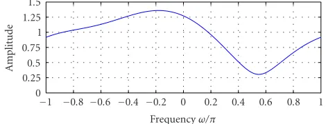
Figure5: Amplitude response of the baseband-equivalent channel H(z)=H1(z) +jHQ(z) used in the simulation.
the literature, for example, [14,15,16,21], but the formu-lation given in this paper using the I/Q separation approach has not been considered so far. In general, the solutions re-lating blind deconvolution and blind signal separation call for input data with independent samplesin time. Notice that this assumption is not needed here, but the I and Q compo-nents of the input data were assumed independent. Notice also that the complexity of the signal model is here signifi-cantly lower (only 2×2) compared to other approaches dis-cussed in [14,15,16,21].
5.2. Simulation example
Some example results of computer simulations are given next to illustrate the efficiency of the proposed equalizer concept. A 16-QAM data modulation with independent I and Q com-ponents (zI(k) andzQ(k)) is used, and the transmitted sig-nal travels through an example baseband-equivalent chan-nel whose amplitude response is depicted in Figure 5. The “notch” in the used channel is around 13 dB below the max-imum amplitude response level. As can easily be verified, this channel fulfills the identifiability condition mentioned in
Section 5.1. The system also includes additive white Gaussian noise (AWGN), with the signal-to-noise ratio (SNR) being set to 20 dB in this experiment. The I and Q samples of the channel distorted noisy signal (seeFigure 6a) are then pro-cessed using the natural gradient-based separation algorithm [20] with nine-tap FIR separation filters. A third-order non-linearity is used in the algorithm and the step-size is 0.001. With these selections, it takes around 5000 iterations to reach the steady state in a stationary environment.
The first two components T1,1(z) and T1,2(z) (with Tm,n(z) = [T(z)]mn) of the total equivalent systemT(z) = W(z)A(z) are depicted in the steady state in terms of their amplitude responses in Figure 7. The other two are not shown due to symmetry (i.e., T2,1(z) = −T1,2(z) and T2,2(z) = T1,1(z)). Obviously, the first output y1(k) forms a good estimate ofzI(k) and the other outputy2(k) ofzQ(k), since the crosstalk between I and Q is around 30 dB below the target signal level. In other words, y1(k) + j y2(k) is a good estimate of the transmitted complex data and the chan-nel equalization is successful. This is further illustrated in
−3
−2
−1 0 1 2 3
IM
−3 −2 −1 0 1 2 3
RE (a)
−2
−1 0 1 2
IM
−2 −1 0 1 2
RE (b)
Figure6: Symbol rate received samples (16-QAM) (a) without and (b) with I/Q signal separation-based equalization. Additive noise SNR is 20 dB.
iteration number. As can be seen, the total impulse response really converges to an impulse (or a delayed impulse in gen-eral), verifying successful equalization. The symbol rate out-put samples without and with I/Q signal separator are de-picted inFigure 6.
Next we assess the symbol error rate (SER) performance of the proposed equalizer, considering the given channel and varying the SNR from 10 dB to 20 dB. For reference purposes, the observed signal is also processed by a traditional training-based equalizer [6, 22] whose coefficients (also a nine-tap complex FIR filter) are adapted using the well-known least-mean-square (LMS) algorithm [22]. The resulting symbol er-ror rates for both equalizers are depicted inFigure 9, evidenc-ing surprisevidenc-ingly similar performance from the SER point of view. The BSS-based solution, however, does not need any training data and thus results in increased effective user data rates.
Generally speaking, it should be noted that the pro-posed I/Q separation-based equalizer, as any linear equalizer, suffers from the noise enhancement in channels with deep notches within the signal band. This is, however, common
−50
−40
−30
−20
−10 0
A
m
plitude
(dB)
−1 −0.5 0 0.5 1
Frequencyω/π (a)
−50
−40
−30
−20
−10 0
A
m
plitude
(dB)
−1 −0.5 0 0.5 1
Frequencyω/π (b)
Figure7: The first two components (a)T1,1(z) and (b)T1,2(z) of the total equivalent system matrixT(z)=W(z)A(z) in the steady state, the other two are not shown due to symmetry (T2,1(z)= −T1,2(z) andT2,2(z)=T1,1(z)). The separatorw(z) is adapted using the nat-ural gradient-based algorithm with step-size 0.001. Additive noise SNR is 20 dB.
to all linear filtering-based techniques [6] and the signal separator-based approach is no different in this sense. Notice also that the computational complexity of any blind equal-ization technique is naturally higher than that of the tradi-tional training-based solutions. However, the computatradi-tional complexity of the proposed approach remains very reason-able due to the small dimension (only 2×2) of the used signal models, contrary to many other blind techniques reported in the literature [14,15,16,21]. To obtain faster convergence, separation approaches exploiting the distinct properties of individual modulation schemes, such as finite alphabet or constant modulus, can be used and constitute an interesting topic for future research.
5.3. General discussion
0 0.2 0.4 0.6 0.8
Er
ro
r
n
or
m
0 2000 4000 6000 8000 10000
Iteration no.
Figure8: The error norm of the effective total equivalent impulse response of the equalized system with respect to a pure impulse as a function of the iteration or adaptation index. Additive noise SNR is 20 dB.
10−3 10−2 10−1 100
Sy
m
b
o
l
er
ro
r
ra
te
10 12 14 16 18 20
SNR (dB) BSS
LMS
Figure9: Symbol error rate of the blind I/Q signal separator-based channel equalizer (BSS) for 16-QAM data. Also shown for reference is the symbol error rate for a traditional training-based equalizer utilizing the well-known least-mean-square (LMS) algorithm.
bandpass channel dispersion were derived, resulting in in-stantaneous and convolutive I/Q mixtures, respectively. To simplify the notations and stay focused on the fundamentals, these two general scenarios were treated separately. Now, the generalized signal model covering all these effects simultane-ously can be written as
xI(k)
xQ(k)
=
cos(∆ωk+θ) sin(∆ωk+θ) −gsin(∆ωk+θ+φ) gcos(∆ωk+θ+φ)
× hhI(k) −hQ(k)
Q(k) hI(k)
∗
zI(k)
zQ(k) .
(23)
The observed signalsxI andxQ can thus be interpreted as instantaneous mixtures of the channel filtered I and Q data.
In other words, an adaptive instantaneous signal separator can be used to form estimates of hI ∗zI −hQ ∗zQ and
hQ∗zI+hI∗zQwiththe effect of (possible) instantaneous de-pendence due to the “zero-delay” taphI(0)+jhQ(0)removed.
After that, a convolutive signal separator (or any other chan-nel equalization technique) can be used to remove the dis-persive mixture effects. Thus, in general, the whole structure is comprised of two parts—one accounts for instantaneous mixing and the other for convolutive effects. Given that the instantaneous “part” of the total mixing system in (23) is re-ally time-varying (frequency offset), this cannot be avoided in general, since the order of formal multiplication (×) and convolution (∗) in (23)cannot be interchanged. However, should there be no frequency offset or it is removed by other means beforehand, (23) can indeed be written as asingle con-volutive type mixture model. In this case, a single concon-volutive I/Q separation stage can directly estimate the original I and Q data. Notice, however, that the beautiful symmetry, discussed inSection 5(see, e.g., (20)), is in this case lost, increasing the computational complexity to some extent.
6. CONCLUSIONS
In this paper, blind I/Q signal separation-based approaches for receiver signal processing were proposed. More specifi-cally, the I/Q mismatches and carrier offsets as well as the lin-ear distortion due to general bandpass channels were shown to create crosstalk between the transmitted I and Q sig-nals. Then compensation structures utilizing blind signal separation were used to compensate for these effects. Also some simulation results were given to illustrate the efficiency of the proposed techniques. Combining the presented I/Q mismatch and carrier offset compensation and the channel equalizer principles into a single (or a cascade of two) I/Q separator(s) results in a versatile receiver building block for future radio communication systems. Future work should be directed to further verification and prototyping of the pro-posed approaches using measured real-world receiver front-end signals.
Generally speaking, the idea behind this paper is to give new views for applying complex or I/Q signal processing ef-ficiently in radio receiver design and to take full advantage of the rich signal structure inherent to complex-valued com-munications signals.
ACKNOWLEDGMENTS
REFERENCES
[1] S. Mirabbasi and K. Martin, “Classical and modern receiver architectures,”IEEE Commun. Mag., vol. 38, no. 11, pp. 132– 139, 2000.
[2] A. A. Abidi, “Direct-conversion radio transceivers for digital communications,”IEEE J. Solid-State Circuits, vol. 30, no. 12, pp. 1399–1410, 1995.
[3] J. Crols and M. S. J. Steyaert, “Low-IF topologies for high-performance analog front ends of fully integrated receivers,” IEEE Trans. Circuits Syst. II, vol. 45, no. 3, pp. 269–282, 1998.
[4] J. Crols and M. S. J. Steyaert,CMOS Wireless Transceiver De-sign, Kluwer Academic, Dordrecht, the Netherlands, 1997. [5] M. E. Frerking,Digital Signal Processing in Communication
Systems, Chapman & Hall, New York, NY, USA, 1994. [6] E. A. Lee and D. G. Messerschmitt,Digital Communication,
Kluwer Academic, Norwell, Mass, USA, 1988.
[7] M. Valkama, “Advanced I/Q signal processing for wideband receivers: models and algorithms,” Ph.D. Dissertation, Tam-pere University of Technology, TamTam-pere, Finland, 2001. [8] G. Fettweis, M. L¨ohning, D. Petrovic, M. Windisch, P.
Zill-mann, and E. ZimmerZill-mann, “Dirty RF,” inProc. 11th Wireless World Research Forum (WWRF ’04), Oslo, Norway, June 2004. [9] M. Valkama, J. Pirskanen, and M. Renfors, “Signal process-ing challenges for applyprocess-ing software radio principles in future wireless terminals: an overview,”International Journal of Com-munication Systems, vol. 15, pp. 741–769, October 2002. [10] J. P. F. Glas, “Digital I/Q imbalance compensation in a low-IF
receiver,” inProc. IEEE Global Telecommunications Conference (GLOBECOM ’98), vol. 3, pp. 1461–1466, Sydney, NSW, Aus-tralia, November 1998.
[11] M. Valkama and M. Renfors, “Digital I/Q imbalance compen-sation in direct-conversion receivers,” inProc. Workshop on Software Radios (WSR ’02), pp. 51–55, Karlsruhe, Germany, March 2002.
[12] I.-H. Sohn, E.-R. Jeong, and Y. H. Lee, “Data-aided approach to I/Q mismatch and DC-offset compensation in communi-cation receivers,”IEEE Commun. Lett., vol. 6, no. 12, pp. 547– 549, 2002.
[13] J. K. Cavers and M. W. Liao, “Adaptive compensation for im-balance and offset losses in direct conversion transceivers,” IEEE Trans. Veh. Technol., vol. 42, no. 4, pp. 581–588, 1993. [14] S. Haykin, Ed.,Unsupervised Adaptive Filtering, Vol. I: Blind
Source Separation, John Wiley & Sons, New York, NY, USA, 2000.
[15] S. Haykin, Ed.,Unsupervised Adaptive Filtering, Vol. II: Blind Deconvolution, John Wiley & Sons, New York, NY, USA, 2000. [16] A. Hyv¨arinen, J. Karhunen, and E. Oja,Independent Compo-nent Analysis, John Wiley & Sons, New York, NY, USA, 2001. [17] J. Eriksson and V. Koivunen, “Identifiability, separability, and
uniqueness of linear ICA models,”IEEE Signal Processing Lett., vol. 11, no. 7, pp. 601–604, 2004.
[18] J.-F. Cardoso, “Blind signal separation: statistical principles,” Proc. IEEE, vol. 86, no. 10, pp. 2009–2025, 1998.
[19] J.-F. Cardoso and B. H. Laheld, “Equivariant adaptive source separation,” IEEE Trans. Signal Processing, vol. 44, no. 12, pp. 3017–3030, 1996.
[20] S. Amari, S. C. Douglas, A. Cichocki, and H. H. Yang, “Multi-channel blind deconvolution and equalization using the nat-ural gradient,” inProc. 1st IEEE Workshop on Signal Process-ing Advances in Wireless Communications, pp. 101–104, Paris, France, April 1997.
[21] S. C. Douglas and S. Haykin, “On the relationship between blind deconvolution and blind source separation,” in Proc. 31st Asilomar Conference on Signals, Systems, and Computers
(ASILOMAR ’97), vol. 2, pp. 1591–1595, Pacific Grove, Calif, USA, November 1997.
[22] S. Haykin,Adaptive Filter Theory, Prentice-Hall, Upper Saddle River, NJ, USA, 3rd edition, 1996.
Mikko Valkamawas born in Pirkkala, Fin-land, on November 27, 1975. He received the M.S. and Ph.D. degrees (both with hon-ors) in electrical engineering (EE) from Tampere University of Technology (TUT), Finland, in 2000 and 2001, respectively. In 2002 he received the Best Ph.D. Thesis Award from the Finnish Academy of Sci-ence and Letters for his thesis entitled “Ad-vanced I/Q Signal Processing for Wideband
Receivers: Models and Algorithms.” In 2003, he was working as a Visiting Researcher with the Communications Systems and Sig-nal Processing Institute at SDSU, San Diego, Calif. Currently, he is working as a Senior Researcher with the Institute of Communica-tions Engineering at TUT, Finland. His general research interests are in communications signal processing and signal processing al-gorithms for flexible radios.
Markku Renfors was born in Suoniemi, Finland, on January 21, 1953. He received the Diploma Engineer, Licentiate of Tech-nology, and Doctor of Technology Degrees from Tampere University of Technology (TUT), Finland, in 1978, 1981, and 1982, respectively. He held various research and teaching positions at TUT during the period from 1976 to 1988. In the years 1988–1991 he was working as a Design Manager in the
area of video signal processing, especially for HDTV, at Nokia Re-search Centre and Nokia Consumer Electronics. Since 1992 he has been a Professor of Telecommunications at TUT. His main research area is signal processing algorithms for flexible radio receivers and transmitters.
Visa Koivunenreceived his D.S. Tech. de-gree with honors from the Department of Electrical Engineering, University of Oulu, and was selected the Primus Doctor (Best Graduate) in years 1990–1994. From 1992 to 1995 he was a Visiting Researcher at the University of Pennsylvania, Philadel-phia, USA. In 1996 he held a faculty posi-tion at the Department of Electrical Engi-neering, University of Oulu. From August