I
II
II
GENERALIZED
COMMUNICATIONS
CONTROL
ROUTINE
This manual is published by the Univac Division of Sperry Rand Corporation in loose leaf format. This format provides a rapid and complete means of keeping recipients apprised of UNIV AC Systems developments. The infor-mation presented herein may not reflect the current status of the product. For the current status of the product, contact your local Univac Represent-ative.
The Univac Division will issue updating packages, utilizing primarily a page-for-page or unit replacement technique. Such issuance w ill provide notification of hardware or software changes and refinements. The Univac Division reserves the right to make such additions, corrections, and/or deletions as, in the judgment of the Univac Division, are required by the development of its Systems.
UNIV AC is a registered trademark of Sperry Rand Corporation.
UP-7816
UNIVAC 9200/920011/9300/9300 II
GENERALIZED COMMUNICATIONS CONTROL ROUTINE
CONTENTS
1. INTRODUCTION
1.1. GENERAL
1.2. MACRO INSTRUCTIONS 1.2.1. Declarative Macro Instructions 1.2.2. Imperative Macro Instructions
1.3.
PROGRAMMING CONVENTIONS1.4. STATEMENT CONVENTIONS
2. GENERALIZED COMMUNICATIONS CONTROL ROUTINE
2.1. GENERAL
2.2. COMPATIBILITY
2.3. MINIMUM HARDWARE AND SOFTWARE CONFIGURATIONS
2.4. STORAGE REQUIREMENTS
2.5. USER PROGRAM INTERFACE REQUIREMENTS
2.6. OPERATOR INTERFACE REQUIREMENTS
2.7. DECLARATIVE MACRO INSTRUCTION
2.8. IMPERATIVE MACRO INSTRUCTIONS 2.8.1. OPEN Macro Instru ction
2.8.2. GET Macro Instruction 2.8.3. PUT Macro Instruction 2.8.4. CLOSE Macro Instruction
Contents
SECTION:
CONTENTS
1
to
4
1-1
to 1-4
1-1
1-1
1-2 1-3
1-3
1-4
2-1
to
2-132-1
2-1
2-1
2-3
2-5
2-5
2-5
2-11 2-11
2-12 2-12 2-13
1 PAGE:
UP-7816
"
-~ . .:c .. _
UNIVAC 9200/920011/9300/9300 II Contents
GENERALIZED COMMUNICATIONS CONTROL ROUTINE SECTION:
3. GCCR FILE CONTROL TABLE AND I/O FUNCTION PACKET FORMAT 3-1 to 3-21
3.1. G EN E RAL
3.2. GCCR FILE CONTROL TABLE 3.2.1. Entry Relay Instruction Area 3.2.2. Input File Control Area
3.2.2.1. Input Buffer Address (Bytes 28-29) 3.2.2.2. Current Input Area Address (Bytes 30-31) 3.2.2.3. Input Time Countdown (Bytes 32-33)
3.2.2.4. In put Message Length Cou ntdown (By tes 34-35) 3.2.2.5. Buffer Control Word Address (Bytes 36-37) 3.2.2.6. Input Interrupt Pack Address (Bytes 38-39) 3.2.2.7. Input Indicator Code Address (Bytes 40-41) 3.2.2.8. Input Unit Activity Value (Bytes 42-43) 3.2.2.9. First Packet Ad dress (By tes 44-45) 3.2.2.10. End Chain Packet Address (Bytes 46-47) 3.2.2.11. Control (Byte 48)
3.2.2.12. Receive Channel (Byte 49)
3.2.2.13. Latest Packet Address (Bytes 50-51) 3.2.2.14. Indicator Code Packet Address (Bytes 52-53) 3.2.2.15. Error Sense Bytes (Bytes 54-55)
3.2.3. Output File Control Area 3.2.4. Control Area
3.2.4.1. Current Input Buffer Address (Bytes 84-85) 3.2.4.2. Input Move Length (Byte 86)
3.2.4.3. Output Move Length (Byte 87)
3.2.4.4. Current Output Buffer Address (Bytes 88-89) 3.2.4.5. RDEVA (Byte 90)
3.2.4.6. TDEVA (Byte 91)
3.2.4.7. Allocation Code (Bytes 92-93)
3.3. I/O FUNCTION PACKETS 3.3.1. Time and I/O Field 3.3.2. Function Field 3.3.3. Status Field 3.3.4. Address Field 3.3.5. Message Length Field 3.3.6. User Control Field 3.3.7. Control Field 3.3.8. Chain Field
3.3.9. Typical Function Packet Coding
3.4. MULTIPLE REQU EST PACKET
3.5. INPUT AND OUTPUT DATA TRANSFER 3.5.1. Input Data Transfer
3.5.2. Output Data Transfer
UNIVAC 9200/9200 11/9300/9300 II Contents 3 UP-7816 GENERALIZED COMMUNICATIONS CONTROL ROUTINE SECTION: PAGE:
4. PACKET ADVANCE 4-1 to 4-4
\..-I
4.1. GEN ERAL 4-14.2. PACKET ADVANCE (EXCLUDING PACKET CHAINING) 4-1 4.3. PACKET ADVANCE (INVOLVING PACKET CHAINING) 4-2 4.3.1. Packet Chaining in I/O Function Packets 4-2 4.3.2. Packet Chaining in Mu Itiple Request Packets 4-2 4.3.2.1. Half-Duplex Mode Multiple Request Considerations 4-3 4.3.2.2. Full-Duplex Mode Multiple Request Considerations 4-4 4.4. THE EFFECT OF CONTROL FUNCTIONS ON PACKET
ADVANCE 4-4
4.5. THE EFFECT OF INDICATOR CODINGS ON PACKET
ADVANCE 4-4
5. ERROR CONDITIONS AND RECOVERY 5-1 to 5-5
5.1. GENERAL 5-1
5.2. ERROR RECOVERY INVOLVING OPERATOR INTERVENTION 5-1 5.3. USE OF INDICATOR CODING FOR ERROR RECOVERY 5-2
5.3.1. Use of I/O Register 5-2
5.3.2. Options Available to the Problem Program 5-3 5.3.3. En try and Exi t of Indi cato r Coding 5-3 5.3.4. GCCR Action Resulting from Indicator Code Status 5-4
6. PROGRAMMING CONSIDERATIONS 6-1 to 6-3
6.1. GENERAL 6-1
6.2. INITIALIZING A MANUAL DIAL RECEIVE PROGRAM 6-1 6.3. INITIALIZING A MANUAL DIAL, HALF-DUPLEX TRANSMIT
PROGRAM 6-2
6.4. AUTOMATIC DIALING 6-2
6.5. CONTINUOUS READ PAPER TAPE ASRS 6-3
6.6. AUTOMATIC ANSWERING RESTRICTION 6-3
FIGURES
3-1. GCCR File Control Table Format 3-2
3-2. I/O Function Packet Format 3-8
3-3. Initial Command Selection Sequence 3-14
3-4. Typical Output Function Packet Coding 3-18
3-5. Typical Input Function Packet Coding 3-18
3-6. Multiple Request Packet Format 3-19
UNIVAC 9200/920011/9300/9300 II Contents 4
UP-7816 GENERALIZED COMMUNICATIONS CONTROL ROUTINE SECTION: PAGE:
TABLES
2-1.
GCCR - Compatible Remote Terminals and DCS Features2-2
'-JPermitted with Each
2-2.
Storage Requirements for Communication Programs Using GCCR2-4
2-3.
Summary of DTFGC Macro Instruction Keyword Parameters2-10
·3-1.
First Error Sense Byte Repertoire3-7
3-2.
Second Error Sense Byte Repertoire3-7
3-3.
Command Byte Repertoire3-10
3-4.
Status Byte Coding for I/O Function Packet3-16
3-5.
Control Byte Coding for I/O Function Packet3-17
5-1.
Recoverable Display Stops5-2
UP-7816
,,-,",0
UNIVAC 9200/920011/9300/9300 II 1
GENERALIZED COMMUNICATIONS CONTROL ROUTINE SECTION:
1. INTRODUCTION
1.1. GENERAL
This manual describes the Generalized Communications Control Routine (GCCR) provided for a UNIVAC 9200/9300 System/Data Communications Subsystem (DCS) user. The manual includes descriptions concerning hardware/software requirements and configurations, routine compatibility, storage requirements, user and operator interfaces, and the macro instructions necessary to implemen~ the GCCR in a partic-ular progra m.
A knowledge of the UNIVAC 9200/9200///9300/9300// Systems Card Assembler
Pro-grammers Reference, UP-4092 (current version), UNIVAC 9200/9200///9300/9300//
Systems Minimum Operating System Programmers Reference, UP-4S47 (current version),
and the UNIVAC 9200/9200///9300/9300// System Card System IOCS Programmers
Reference, UP-7728 (current version) is helpful in using the manual.
The manual has six sections. A discussion of each section's contents is as follows:
• Section 1 contains introductory information required for understanding the format of the macro instructions, the program conventions, and the statement conventions used within the manual.
• Section 2 contains information pertaining to the use, requirements, and implementa-tion of the GCCR from the user's point of view.
• Section 3 contains information about the. structure and purpose of the tables and packets comprising the GCCR, and descriptions of the events which take place during data input and output transfers.
• Section 4 contains information pertaining to the manner in which the GCCR handles packet advance for function packets submitted through GET and PUT imperative macro instructions and through multiple request packets. Information concerning packet chaining and the effects of control function execution upon packet advance are also discussed.
• Section 5 contains information pertaining to error indications and recovery. Operator response as well as program response to error conditions are also discussed.
• Section 6 contains programming considerations which should be taken into account when communication is established between terminals and a UNIVAC 9200/9300 central processor site.
1.2. MACRO INSTRUCTIONS
A macro instruction is similar in form to a source code instruction. It mayor may not have a label, but it must have an operation code and an operand field containing one or more parameters.
The parameters used with the declarative macro instructions describe all aspects of the file to be processed; the parameters used with the imperative macro instructions point to the file described by a declarative macro and sometimes add additional de-tails specifying processing action to be taken.
1
UP·7816
UNIVAC 9200/9200 11/9300/9300 II 1
GENERALIZED COMMUNICATIONS CONTROL ROUTINE SECTION:
1.2.1. Declarative Macro Instructions
A problem program informs the system of the parameters, special conditions, cur-rent status, and options pertaining to a file. This is accomplished by including a declarative (file definition) macro instruction for each file required by the problem program. These macro instructions generate nonexecutable code, such as constants and storage areas for variables. Therefore, these macro instructions should be separated physically from the inline file processing coding. The declarative macro instruction and the selected keyword parameters in the operand define the file. The first three characters of the operation code are DTF, meaning Define The File. The last two characters indicate the type of device or method of accessing. A keyword parameter consists of a word or code immediately followed by an equals (=) sign which is, in turn, followed by one specification.
The format of the declarative macro instruction is:
LABEL 1i OPERA TION 1i OPERAND
filename DTFxx keyword-l '" x,keyword-2 '" y, ... ,keyword-n '" z
The symbolic name of the file must appear in the label field. It has a maximum of four characters and must begin with an alphabetic character. The appropriate DTF designation must appear in the operation field. The keyword parameters are written in any order in the operand field and must be separated by commas. Appropriate assembler rules regarding macro instructions apply to blank columns and continua-tion statements.
The alternate form of writing the declarative macro instructions is:
LABEL 1i OPERATION 1i
filename DTFxx
OPERAND
keyword-l '" x, keyword-2 '" y,
keyword-n '" z
72
x
X
In the alternate form, a continuation mark is necessary in column 72 of every line except the last. Each keyword parameter and specification, except the last, must be followed by a comma.
2
UP·7816
UNIVAC 9200/920011/9300/9300 II 1
GENERALIZED COMMUNICATIONS CONTROL ROUTINE SECTION:
1.2.2. Imperative Macro Instructions
A problem program must communicate with IOCS in order to accomplish the proces-sing of files that have been defined by declarative macro instructions. This is ac-complished by including imperative (file processing) macro instructions in the problem program, which in turn communicate with the IOCS. The imperative macro instructions are expanded as inline executable code. Not all macro instructions are available for use on all devices. Some are specifically input type macro instructions and cannot be used for a device that is exclusively used for output; the opposite is true for output type instructions. See the detailed descriptions of particular IOCS for the use of imperative macro instructions.
The format of the imperative macro instructions is:
LABEL D OPERATION D OPERAND
[name] xxxx yyyy, ... ,zzzz
A symbolic name can appear in the label field. It can have a maximum of four
characters and must begin with an alphabetic character. The appropriate verb or code must appear in the operation field. The positional parameters (as signified by the name) must be written in the specified order in the operand field and be separated by commas. When a positional parameter is omitted, the comma must be retained to indicate the omission except in the case of omitted trailing parameters. Appropriate assembler rules regarding macro instructions apply to blank columns and continua-tion statements.
1.3. PROGRAMMING CONVENTIONS
A user routine may be required in the main source program that is accessed by the IOCS when certain checking features are required (for example, printer overflow). IOCS automatically stores the program reentry address in register 14 when the branch to the user routine occurs. The user routine is therefore required to provide the neces-sary return linkage to the main source program. If the user routine utilizes register 14, it must preserve and restore register 14 before terminating. This also must be done if any macro instruction is executed by the user routine, since all macros use program registers 14 and 15. If register 14 is not preserved, the reentry address is lost. Reg-ister 15 also may be used by the user routine and it need not be preserved. However, its contents are altered by the execution of any macro instruction.
3
UP·7816
UNIVAC 9200/920011/9300/9300 II 1
GENERALIZED COMMUNICATIONS CONTROL ROUTINE SECTION:
1.4. STATEMENT CONVENTIONS
The conventions used to illustrate statments in the manual are as follows:
• Capital letters and punctuation marks (except braces, brackets, and ellipses) are information that must be coded exactly as shown.
• Lowercase letters and terms represent information that must be supplied by the progra m me r.
• Information contained within braces represents necessary entries, one of which must be chosen.
• Information contained within brackets represents optional entries that (depending on program requirements) are included or omitted. Braces within brackets signify that one of the entries must be chosen if that operand is included.
• An ellipsis indicates the presence of a variable number of entries.
• In the coding of macros, commas are required after each parameter except after the last parameter specified. When a positional parameter is omitted from within a series of parameters, the comma must be retained to indicate the omission.
4
UP-7816
UNIVAC 9200/920011/9300/9300 II 2
GENERALIZED COMMUNICATIONS CONTROL ROUTINE SECTION: PAGE:
2. GENERALIZED COMMUNICATIONS
CONTROL ROUTINE
2.1. GENERAL
The UNIVAC Generalized Communications Control Routine (GCCR) is a logical input/output control routine designed to function as the software interface between a user's problem program and the various remote communication devices of the DCS to which his system is connected. The GCCR enables a user to request the execution of input/output operations without assuming the responsibilities of handling the hardware. The user can, by the use of declarative and imperative macro instructions, develop a communications handler tailored to meet the needs of his particular system configur-ation and problem program requirements.
2.2. COMPATIBILITY
The GCCR can be used with all configurations of the UNIVAC 9200/9300 Systems. This flexibly designed communications subroutine is capable of controlling up to eight communication lines and can be used with any of the terminals connected with either the DCS-1 or DCS-4 configuration.
Another feature making the GCCR compatible with all system configurations is its ability to communicate in both half-duplex and full-duplex modes at telegraph, voice-grade, and w ideband transmission speeds with devices, such as keyboard printers, scopes, teletypewriters, and other processors. The capability of being used in both the symbiont and the main chain modes permits the GCCR to be involved in background batch processing as well as in the more communication-active inquiry and response types of subroutines.
The availability of current UNIVAC 9200/9300 IOCS subroutines makes it possible to interface the GCCR with I/O devices to perform operations, such as remote-to-printer, disc-to-remote, and remote-to-tape.
2.3. MINIMUM HARDWARE AND SOFTWARE CONFIGURATIONS
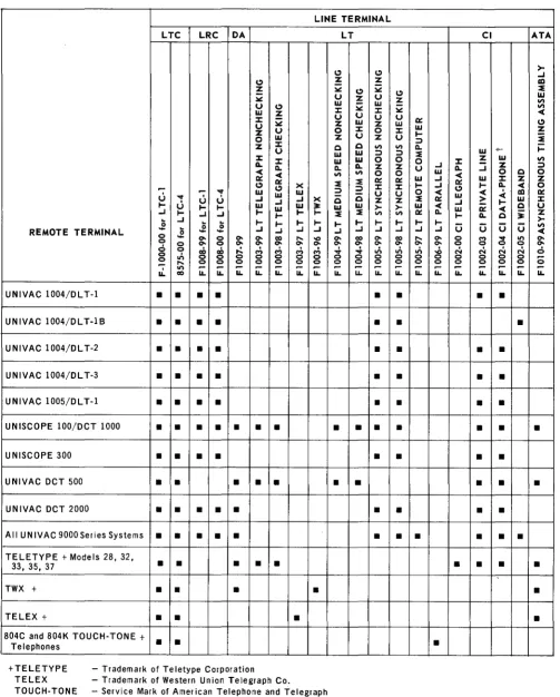
The minimum hardware configuration required for utilization of the GCCR is a UNIVAC 9200/9300 central processor unit with a main storage capacity of at least 8K, 'a card reader, a DCS-1 or DCS-4, and any peripheral device required by the user problem pro-gram. Note that the GCCR element requires 16K of main storage to perform a preassem-bly macro pass or an assempreassem-bly. Once assembled and linked to the DTFGC instruction, the GCCR and applicable subroutines can be operated in an 8K main storage environ-ment. The configuration of the DCS-1 and DCS-4 is comprised of any of the features listed in Table 2-1. (Table 2-1 lists all compatible remote devices available with their respective line terminal.) The large scale systems (UNIVAC 418,494,1107, and 1108) are not listed in Table 2-1, because the GCCR is not designed to replace the REM-1 library nor to serve the needs of the advanced user who wishes to write his own remote terminal program for a UNIVAC 9000 System.
UP·7816
UNIVAC 9200/920011/9300/9300 II
GENERALIZED COMMUNICATIONS CONTROL ROUTINE
LINE TERMINAL
LTC LRC DA LT
C)
C)
-
Zz ~
-
U~
U C) w
W Z J:
J:
-
~ U ZU
U 0
Z
0 W Z
Z J: u C
W
J: J: W
a... a... a...
« «
VIII:: II::
C) C) x
,.
~
~
""r w w ;:)
U
...,
WU ..I ..I X
U U ..I C
I- l- I- W W w :t: w
..I I-..I ..I ..I l- I- l- I-
,.
.E
l5 l5 l- I- l- I-l-REMOTE TERMINAL l5
- -
..I ..I ..I ..I ..I0
-
0- 0 0- 0- co ... -0 0-0 0 0- 0 0- 0- 0- 0- 0-0-0 0 cO cO ,..:. M M M M ...; 0 ,;., 0 0 0 0 0 0 0 0 0 ... 0 0 0 0 0 0 0 0
u..
11'1 ~ ~ ~ ~ ~ ~ ~ ~co IL IL IL IL IL IL IL IL
UNIVAC 1004/0L T-l
•
•
• •
UNIVAC 1004/0L T-18
•
•
• •
UNIVAC 1004/0L T-2
• • • •
UNIVAC 1004/0L T-3
• • • •
UNIVAC 1005/0L T-l
•
• • •
UNISCOPE 100/OCT 1000
• • • • • • •
•
UNISCOPE 300
• •
•
•
UNIVAC OCT 500
• •
• • •
•
UNIVAC OCT 2000
•
•
• • •
All UNIVAC 9000Series Systems
• • • • •
TELETYPE + Models 28, 32,•
•
•
• •
33, 35, 37
TWX +
•
•
•
•
TELEX +
• •
•
804C and 804K TOUCH-TONE +
•
•
Telephones
- Trademark of Teletype Corporation - Trademark of Western Union Telegraph Co.
- Service Mark of American Telephone and Telegraph
+TELETYPE TELEX TOUCH-TONE
TWX - Trademark of American Telephone and Telegraph Co.
DATA PHONE - Trademark of American Telephone and Telegraph Co.
C) Z
-C) ~
Z U
-
w~ J: U U
W Z
J: 0
U Z
C VI
W ;:)
W 0
a... z
VI 0
,.
II:: ;:) J:u
-C Z
w
>-,.
VII-
l-..I ..I
co 0-0- 0-...; ,;., 0 0 0 0
~ ~
IL IL
•
•
•
•
•
• •
•
•
•
•
2 SECTION: CI C) Z -~ U II::W
J: W
I-U ;:) VI a...
;:)
,.
W0 0 J: Z
z U ..I a... ..I
0 w
«
II:: W ..I II:: W
J: I- ..I C)
I-u 0
,.
«
W«
II:: > Z ..I
>- w
«
w II:: VI II:: a... I- a...I- l- I-
-..I ..I ..I U U
co ... 0- 0
8
0- 0- 0- 0 ,;., ,;., ..0 N N0 0 0 0 0 0 0 0 0 0
~ ~ ~ ~ ~
IL IL IL IL IL
•
•
•
•
•
•
•
•
•
•
•
•
•
•
•
•
•
•
•
• •
•
Table 2-1. GCCR - Compatible Remote Terminals and DCS Features Permitted With Each
2 PAGE: ATA >-..I In
,.
W VI VI«
C) Z,.
-+-I-W VI
Z ;:)
0 c 0
J: Z Z
a...
«
0<
In II::W J:
l-«
C Uc :t: >-Z
- -
VI U u«
...,
11'10-0 0
0-N 0-N 0
0 0 C; 0 0
~ ~ ~
IL IL IL
UP-7816
UNIVAC 9200/920011/9300/9300 II 2
GENERALIZED COMMUNICATIONS CONTROL ROUTINE SECTION:
The minimum software configuration required for us ing the GCCR is the Minimum Operating System (MOS). The GCCR is also designed to function in both the Non-. current Operating System (NCOS) and the Concurrent Operating System (COS)Non-. IOCS
routines available for use with the GCCR are:
• Drum Printer
• Inte gra ted Printer
• Integrated Reader
• On-Line UNIVAC 1001 Controller • Serial Punch
• Row Punch
• Paper Tape Reader
• Paper Tape Punch
• Magnetic Tape
• UNIVAC 8410 Disc • UNIVAC 8411 Disc • UNIVAC 8414 Disc 2.4. STORAGE REQUIREMENTS
The amount of storage required for a communication program handled by the GCCR is based upon the type, configuration, and complexity of the system being used. A factor to be considered when determining storage requirements is the number of remote terminals employed. The amount of buffer required for each remote terminal must be
sufficient to contain a portion of message considered excessively long or to contain the entire message for those considered relatively short. User coding must also be cons idered. F or example, user coding is required to test and reset the ind ications pro-vided in the status bytes of the I/O function packets used by the GCCR; the user coding is also required to initiate activities, such as processing a subsequent record, initiating a retransmission of data, or cancelling a program. The activity initiated by the user program must be appropriate to the status detected. When 10CS routines are taken into account, storage requirements vary with respect to the size of the specific 10CS routines used.
PAGE:
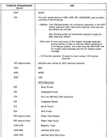
A list of the storage requirements for a communication program using the GCCR is pro-vided in Table 2-2.
UP·7816
UNIVAC 9200/920011/9300/9300 II
GENERALIZED COMMUNICATIONS CONTROL ROUTINE SECTION: 2 PAGE: 4
STORAGE REQUIREMENT USE
(bytes)
2400 GCCR
376 For each remote terminal (KSR, ASR, RO, UNISCOPE, and so forth); consists of the following:
- Buffers: Two 128-byte buffers for full-duplex operation, or for half-duplex operation when optionally separate input and out-put buffers are utilized.
One 128-byte buffer for half-duplex operation (used for both input and output).
- Work area: A work area equal to the largest message expected during transfer of data is required. When operating in a full-duplex system, two areas must be specified: one for largest input message and one for largest output message.
- I/O function packets: 12 bytes for each unique I/O function required.
100 (approximate) Optional user coding for DCS interrupt response
1600 MOS
4000 NCOS
5000 COS
10CS Subroutine
600 Drum Printer
400 Integrated Printer
720 On-Line UNIVAC 1001 Controller
550 Integrated Reader
675 Serial Punch
950 Row Punch
600 (approximate) Paper Tape Reader
600 (approximate) Paper Tape Punch
1200-3100 Magnetic Tape
1300-5800 UNIVAC 8410 Disc
1600-7200 UNIVAC 8411/8414 Disc
UP-7816
UNIVAC 9200/9200 11/9300/9300 II 2
GENERALIZED COMMUNICATIONS CONTROL ROUTINE SECTION: PAGE:
2.5. USER PROGRAM INTERFACE REQUIREMENTS
Interface between the GCCR and the user problem program consists of two requirements, establishing a file description to the IOCS for each file the user program must access and providing the instructions which direct the sequential processing and operation of the GCCR.
The user establishes a file description to the IOCS programs by means of t.e DTFGC declarative macro instruction. The DTFGC macro instruction produces, through the preassembly macro pass, a file control table (see Section 3) for the file described by the keyword parameters provided within the DTFGC macro instruction. The output of the preassembly macro pass may be assembled with the problem program or assembled alone and linked with the problem program. The user, however, must provide a DTFGC declarative macro instruction for each file to be accessed by the user's problem program.
The operation of the GCCR is directed by means of imperative macro instructions which are specified within the user's problem program. The imperative macro
instruc-tions are executed to accomplish specific I/O funcinstruc-tions in proper relainstruc-tionship to the requirements of the problem program. The use of the imperative macro instructions differs from their conventional use in that the imperative macro instructions identify function packets rather than I/O areas. The function packet identified contains a detailed description of the specific I/O order to be executed as well as the control information necessary to execute that order.
2.6. OPERATOR INTERFACE REQUIREMENTS
The interface between the operator and the GCCR is primarily the responsibility of the problem program. The GCCR, however, provides the problem program with the status of the functions executed; the problem program must provide for the interpre-tation of this status information in determining if operator intervention is required.
In some instances, the operator is required to keyin a response or to react to a specific error halt display which signifies that a hardware or software error has been encountered.
The user may provide for the handling of error conditions by the use of indicator cod-ing included in the problem program. The purpose of indicator codcod-ing is to inform the problem program of changes in the status of I/O functions and to direct the initiation of a predetermined error recovery procedure to remedy the situation. The use of the user indicator coding is discussed in detail in Section 3.
2.7. DECLARATIVE MACRO INSTRUCTION
In order to use the GCCR, the programmer defines to the IOCS each input and output file requiring the use of a communications device. This is accomplished by means of a DTFGC declarative macro instruction. (DTFGC is the mnemonic operation code for Define The File for the Generalized Communications Control Routine.)
~ .... UP-7816
UNIVAC 9200/9200 11/9300/9300 II 2
GENERALIZED COMMUNICATIONS CONTROL ROUTINE SECTION:
The DTFGC macro instruction provides the keyword parameters to which the pre-assembly macro pass can generate a source code module comprised of a file control table. The keyword parameters of the macro instruction are converted and inserted in the file control table as entries which interface the file to the control routine and which are used to direct the operation of the GCCR. The file control table module pro-duced by the preassembly macro pass may be assembled as part of the user program or may be assembled alone and then linked with the problem program.
PAGE:
The filename entered into the label field of a DTFGC macro instruction must corre-spond to the symbolic name assigned to the file by the programmer. Each symbolic name assigned is restricted to four characters in length and must conform to the assembler language rules for labels.
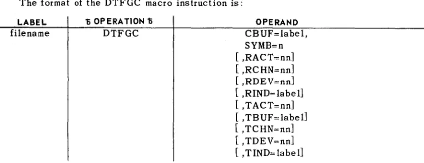
The format of the DTFGC macro instruction is shown below with each required or optional keyword parameter in alphabetical order. A description of the parameters and their specifications follows the format, and a summary of the keyword parameters is given in Table 2.3.
The format of the DTFGC macro instruction is:
LABEL D OPERATION D
filename DTFGC
• Communications Buffer
OPERAND CBUF=label, SYMB=n [ ,RACT=nn] [ ,RCHN=nn] [ ,RDEV=nn] [ ,RIND=labe1l [ ,TACT=nn] [ ,TBUF=label] [ ,TCHN=nn] [ ,TDEV=nn] [ ,TIND=label]
This keyword parameter is required for input files that are to be executed by the GCCR. It is used to identify a problem program area (128 bytes in length, modulo 128) to be used as a dynamic buffer for receiving input messages and subsequently to transfer this data to the areas specified in the address fields of function packets. The buffer area specified by the communications buffer keyword parameter serves as both an input and output area whenever the TBUF parameter is omitted from the DTFGC macro instruction. The format of the communications buffer keyword parameter is:
CBUF=label
where label is the address of the dynamic buffer area.
NOTE: To ensure that it conforms to the modulo 128 restrictions, the CBUF area is defined in the problem program as follows:
ORG *,128 label DS CL128
UP-7816
UNIVAC 9200/920011/9300/9300 II 2
GENERALIZED COMMUNICATIONS CONTROL ROUTINE SECTION:
• Output Buffer
This keyword parameter is used to identify a program area (128 bytes in length, modulo 128) to be used as a dynamic buffer for outputting data. The data outputted is transferred from the area specified in the address field of the function packet to a remote terminal. This parameter must be specified for full-duplex modes of oper-ation and for half-duplex modes of operoper-ation when separate input and output buffers are employed. The output buffer parameter is to be omitted for simplex modes of operation and half-duplex modes of operation where only one 128-byte buffer is utilized. When only one buffer is employed, the area specified by the CBUF key-word parameter serves as both the input and output dynamic buffer. The GCCR assumes that a full-duplex environment is intended whenever separate buffers (CBUF and TBUF) are specified.
When operating with separate input and output buffers in a half-duplex environment, caution must be exercised so that commands to both input and output line terminals do not overlap and cause a "loop back" situation of transferring data from the
out-PAGE:
put buffer to the input buffer. This condition will cause unrecoverable error situations.
The format of the output buffer keyword parameter is:
TBUF::label
where label is the address of the dynamic buffer area.
NOTE: To ensure that it conforms to the modulo 128 restrictions, the TBUF area
is defined in the problem program as follows:
ORG *,128
label DS CL128
• Symbiont
This required keyword parameter is used to specify the allocation code assigned to the communication devices employed by the file. The value specified for this parameter must correspond to the level of the routine with which the communication device is to operate. The format for the symbiont keyword parameter is:
SYMB::n
where n is a decimal number from 1 to 5 representing the symbiont number when the communications control routine is incorporated into a symbiont, or n is equal to the decimal value of 6 representing the allocation code for the main program.
• Receive Available Cycle Time
This keyword parameter is required whenever the GCCR handles input messages. It is used to specify the percentage of available memory cycles (activity sum) required by the slowest device in the input communication linkage. Items which must be considered in determining the degree of slowness of a device are the communications channel itself, the line terminal speed, and the modem speed. The format of receive available cycle time keyword parameter is:
RACT::nn
where nn is a value from 01 to 100 percent.
UP-7816
UNIVAC 9200/920011/9300/9300 II 2
GENERALIZED COMMUNICATIONS CONTROL ROUTINE SECTION:
The following table provides typical examples of the values specified for the RACT parameter when associated with data sets having the baud rates listed.
DATA SET
201A3
201B3 or 202D 205Bl
301B or 303C
• Receive Channel Entry
BAUD RATE
2000 2400 4800 50,000
VALUE OF RACT
(Percent)
1
1 1
10
This keyword parameter is used whenever an input message is handled by the GCCR. When specified, the parameter identifies the multiplexer subchannel to which the receiver of the data communications subsystem is connected and must agree with the PUTBL entry of the operating system.
The format for the receive channel entry parameter is: RCHN=nn
where nn may equal any odd numbered decimal integer between the values of 17 and 31.
NOTE: As previously stated, the value specified for the RCHN parameter must agree with the PUTBL entry of the operating system. For example, RCHN would be specified as RCHN=25 if the following PUTBL was used when generating the logical unit/physical unit tables of the operating system.
PUTBL CDVC,25,0,0,4,B,24
• Receive Device
This keyword parameter identifies the logical unit number of the input communica-tions device connected to the multiplexer subchannel specified by the RCHN para-meter and must agree with the PUTBL entry of the operating system. The keyword must be specified whenever the RCHN parameter is specified. The format of the receive device parameter is as follows:
RDEV=nn
where nn is expressed as a decimal number or as a two-digit hexadecimal number having an X'nn' format. The value for nn is any number from 00 through 63.
NOTE: As previously stated, the value of RDEV must agree with the PUTBL entry of the operating system. For example, RDEV would be specified as RDEV=4 if the following PUTBL was used when generating the logical unit and
physical unit tables of the operating system. PUTBL CDVC,25" ,4,B,24
8
UP-7816
UNIVAC 9200/9200 11/9300/9300 II 2
GENERALIZED COMMUNICATIONS CONTROL ROUTINE SECTION:
• Receive Indicator Code
This keyword parameter is used only when the problem program employs the use of indicator coding to handle interrupts resulting from error conditions; error conditions may occur while receiving an input data transfer from a remote communications device. When specified, this parameter identifies the problem program indicator code routine address. The format of the receive indicator code is:
RIND=label
where label is the tag of the first instruction to be executed in the I/O mode for interrupt conditions resulting from data input from remote communication devi~es.
• Transmit Available Cycle Time
This keyword parameter is required whenever the GCCR handles output messages. The parameter specifies the percentage of available memory cycles required by the slowest device in the output communication linkage. Items to be considered in deter-mining the degree of slowness of a device are the communications channel itself, the line terminal speed, and the modem speed. The format of transmit available cycle time keyword parameter is:
TACT=nn
where nn is a value from 01 to 100 percent.
The following table provides typical examples of the values specified for the TACT parameter when associated with the data sets having the baud rates listed.
DATA SET
201A3
201B3 or 202D 205B1
301B or 303C
• Transmit Channel Entry
BAUD RATE
2000 2400 4800 50,000
VALUE OF TACT
(Percent)
1 1
1
10
This keyword parameter is used whenever an output message is handled by the GCCR. When specified, the parameter identifies the multiplexer subchannel to which the transmitter of the data communications subsystem is connected. The format for the transmit channel entry parameter is:
TCHN=nn
where nn may equal any even numbered decimal integer between the values qf 16 and 30.
9
UP-7816
UNIVAC 9200/920011/9300/9300 II 2
GENERALIZED COMMUNICATIONS CONTROL ROUTINE SECTION:
• Transmit Device
This keyword parameter identifies the logical unit number of the output communi-cations device connected to the multiplexer subchannel specified by the TCHN parameter. When specified, the TCHN parameter must agree with the PUTBL entry of the operating system. The keyword parameter must be specified whenever the TCHN parameter is specified. The format of the transmit device parameter is:
TDEV=nn
where nn may be expressed as a decimal number or as a two-digit hexadecimal number having an X'nn' format. The value for nn is any number from 00 through 63.
NOTE: As previously stated, the value of TDEV must agree with the PUTBL entry of the operating system. For example, TDEV would be specified as TDEV=4 if the following PUTBL was used when generating the logical unit and physical unit tables of the operating system.
PUTBL CDVC,25" ,4,B,24
• Transmit Indicator Code
PAGE:
This keyword parameter is used only when the problem program employs the use of indicator coding to handle interrupts resulting from error condition; error conditions may occur during the transmission of output data to a remote communications device. When specified, this parameter identifies the problem program indicator code routine address. The format of the transmit indicator code is:
TIND=label
where label is the tag of the first instruction to be executed in the I/O mode for interrupt conditions resulting from data output to a remote communications device.
KEYWORD SPECIFICATION
CBUF label
SYMB
~
RACT RCHN RDEV RIND TACT TCHN TDEV TINDR = required X = optional
1
~o
5~
1 to 100
nn = odd number subchannel (17 to 31)
nn = logical unit
label
1 to 100
nn =even number subchannel (16 to 30)
nn = logical unit
label
FILES
INPUT OUTPUT REMARKS
R R Identifies dynamic buffer area
R R Identifies GCCR as a symbiont or as part of the main program
R Percentage of memory cyc les ava i lab Ie for s lowest input device
R Identifies receiver subchannel
R Identifies logical unit number of rec~iver
X Specifies use of indicator coding for input interrupt hand ling
R Percentage of memory cycles avai lable for s lowest output device
R Identifies transmitter subchannel
R Identifies logical unit number of transmitter
X Specifies use of indicator coding for output interrupt handling
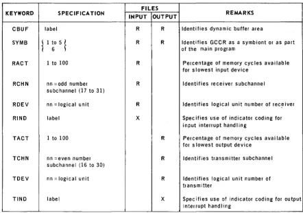
Table 2-3. Summary of DTFGC Macro Instruction Keyword Parameters
UP-7816
UNIVAC 9200/920011/9300/9300 II 2
GENERALIZED COMMUNICATIONS CONTROL ROUTINE SECTION:
Example:
LABEL t OPERATION 11 OPERAND
10 16
2.8. IMPERATIVE MACRO INSTRUCTIONS
Imperative macro instructions supplied for the GCCR are used to open, close, and process the files required by the problem program. By including the appropriate imperative macro instructions within the problem program, the user directs the opera-tion of the GCCR so that specific I/O funcopera-tions are accomplished in proper relaopera-tion to the requirements of the problem program.
The imperative macro instructions supplied for the GCCR are OPEN, GET, PUT, and CLOSE. Optional labels for these macro instructions are restricted to a maximum of four characters.
2.8.1. OPEN Macro Instruction
The OPEN imperative macro instruction initializes and prepares the file for pro-cessing. This macro must be issued before any other macro instruction pertaining to the same file is issued.
When executed, the OPEN macro instruction initializes the file control table of the named file. No data transfer is initiated however.
The format of the OPEN imperative macro instruction is:
LABEL D OPERATION D OPERAND
[name] OPEN filename
• Positional Parameter 1
filename - is the symbolic name of the file to be opened as specified in the label field of the DTFGC declarative macro instruction. The file-name may have a maximum of four characters.
11
PAGE:
UP-7816
UNIVAC 9200/920011/9300/9300 II 2
GENERALIZED COMMUNICATIONS CONTROL ROUTINE SECTION:
Example:
LABEL 11 OPERATION 11 OPERAND 11
10 16
Initializes the files labeled CARD and COMM. 2.8.2. GET Macro Instruction
The GET imperative macro instruction is used to submit a request for the execution of an input function on the receive channel specified by the RCHN parameter of the DTFGC macro instruction.
The format of the GET imperative macro instruction is:
LABEL D OPERATION 1; OPERAND
[name] GET filename ,packet
• Positional Parameter 1
filename - is the symbolic name of the file to be accessed as defined in the label field of the DTFGC declarative macro instruction .
• Positional Parameter 2
packet - the symbolic name of the
I/o
function packet which contains the details for the input function to be executed.Example:
LABEL 11 OPERATION 11 OPERAND
10 16
I I I I I I I I I
Places a request into the function execution list for the execution of the I/O function packet label INAR for the file labeled COMM.
2.8.3. PUT Macro Instruction
The PUT imperative macro instruction is used to submit a request for the execution of an output function on the transmit channel specified by the TCHN parameter of the DTFGC macro instruction.
The format of the PUT imperative macro instruction is:
LABEL 1; OPERATION 1; OPERAND
[name] PUT filename ,pac ket
12
UP-7816
UNIVAC 9200/9200 11/9300/9300 II 2
GENERALIZED COMMUNICATIONS CONTROL ROUTINE SECTION:
• Positional Parameter 1
filename - is the symbolic name of the file to be accessed as defined in the label field of the DTFGC declarative macro instruction.
• Positional Parameter 2
Example:
LABEL
packet - the symbolic name of the I/O function packet which contains the details for the output function to be executed.
11 OPERA 1101'411 OPERAND
10 16
Places a request in the function execution list for the execution of the I/O function packet labeled OUT which transmits to the file labeled COMM.
2.8.4. CLOSE Macro Instruction
The CLOSE imperative macro instruction ensures the proper closing of a file after all processing has been completed. A file may be closed at any time. Once closed, a file can no longer be accessed unless that file is reopened by means of an OPEN macro instruction. To ens ure proper closing of a file, the CLOSE macro instruction should be executed before the problem program goes to the end-of-job (EO]).
The format of the CLOSE imperative macro instruction is:
LABEL 15 OPERATION 15 OPERAND
CLOSE filename
• Positional Parameter 1
Example:
LABEL
filename - is the symbolic name of the file to be closed as specified in the label field of the DTFGC declarative macro instruction. The filename may have a maximum of four characters.
11 OPERA 1101'411 OPERAND
10 16
Closes the files labeled CARD and COMM.
13
UP-7816
3.
UNIVAC 9200/920011/9300/9300 II 3
GENERALIZED COMMUNICATIONS CONTROL ROUTINE SECTION:
GCCR FILE
FUNCTION
CONTROL TABLE AND
PACKET FORMATS
I/O
3.1. GENERAL
To understand the manner in which the GCCR functions, one must have a basic knowledge of the purpose, structure, and contents of the tables and packets utilized by the GCCR. Descriptions, therefore, are provided for both the GCCR file control table and the I/O function packets comprising the GCCR. In addition, descriptions are provided for the format of the multiple request packet available with the GCCR and for the events occurring during a typical input and output data transfer.
3.2. GCCR FILE CONTROL TABLE
The file control table serves as the primary interface between the user problem pro-gram and the GCCR. Through the use of this table, the user defines the characteristics and the amount of control desired for each file serviced by the GCCR. The entries into the file control table are derived from the keyword parameters of the DTFGC macro instruction and from the dynamic operating status recorded by the GCCR. The GCCR uses the contents of the table to issue I/O orders as directed by the user program and to maintain the status of these orders for the problem program.
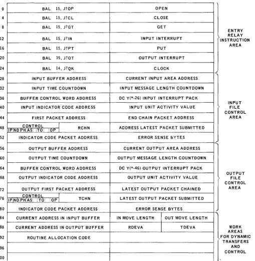
Each file control table generated has four functional areas: entry relay instruction area, input file control area, output file control area, and control area. Figure 3-1 illustrates the format of the file control table.
1
UP·7816
o
4 8 12 16 20 24 28 32 36 40 44 48 52 56 60 64 68 72 76 80 84 88 92 96 100UNIVAC 9200/920011/9300/9300 II
GENERALIZED COMMUNICATIONS CONTROL ROUTINE SECTION:
BAL 15, J?OP OPEN
BAL 15, J?CL CLOSE
BAL 15, J?GT GET
BAL 15, J?IN INPUT INTERRUPT
BAL 15, J?PT PUT
BAL 15, J?OT OUTPUT INTERRUPT
BAL 14, J?QK CLOCK
INPUT BUFFER ADDRESS CURRENT INPUT AREA ADDRESS
INPUT TIME COUNTDOWN INPUT MESSAGE LENGTH COUNTDOWN
BUFFER CONTROL WORD ADDRESS DC Y{*-26) INPUT INTERRUPT PACK
INPUT INDICATOR CODE ADDRESS INPUT UNIT ACTIVITY VALUE
FIRST PACKET ADDRESS END CHAIN PACKET ADDRESS
CONTROL
I
RCHN ADDRESS LATEST PACKET SUBMITTED IP;ND:PH:AS: iTO: :OP IINDICATOR CODE PACKET ADDRESS ERROR SENSE BYTES
OUTPUT BUFFER ADDRESS CURRENT OUTPUT AREA ADDRESS
OUTPUT TIME COUNTDOWN OUTPUT MESSAGE LENGTH COUNTDOWN
BUFFER CONTROL WORD ADDRESS DC Y{*-46) OUTPUT INTERRUPT PACK
OUTPUT INDICATOR CODE ADDRESS OUTPUT UNIT ACTIVITY VALUE
OUTPUT FIRST PACKET ADDRESS LATEST OUTPUT PACKET CHAINED
CONTROL
I
TCHN LATEST OUTPUT PACKET SUBMITTED IP,NDiPH:AS: ;TO: :OP I
INDICATOR CODE PACKET ADDRESS ERROR SENSE BYTES
CURRENT ADDRESS IN INPUT BUFFER IN MOVE LENGTH OUT MOVE LENGTH
CURRENT ADDRESS IN OUTPUT BUFFER RDEVA TDEVA
ROUTINE ALLOCATION CODE
Figure 3-1. GCCR File Control Table Format
3
J
PAGE: ENTRY RELAY INSTRUCTION AREA INPUT FILE CONTROL AREA OUTPUT FILE CONTROL AREA1
WORK AREAS FOR DYNAMICUP-7816
UNIVAC 9200/920011/9300/9300 " 3
GENERALIZED COMMUNICATIONS CONTROL ROUTINE SECTION: PAGE:
3.2.1. Entry Relay Instruction Area
This functional area comprises the first 28 bytes of the file control table. It contains the seven branch and link (BAL) instructions which interface the GCCR to the imper-ative macro instructions specified in the user program. The BAL instructions provide the means to access the OPEN, GET, PUT, and CLOSE entrances to the GCCR as well as entrances for input and output interrupt response.
3.2.2. Input File Control Area
The input file control area consists of bytes 28 through 55. The entries made into the fields of this area serve to control the status of the input (receive) channel of the file. In other than full-duplex operation, the packet address fields of this section maintain control of the function packets for input and output messages in order to achieve the
proper sequence of execution. The contents and information pertinent to the individ-ual fields of this functional area are described in 3.2.2.1. through 3.2.2.15.
3.2.2.1. Input Buffer Address (Bytes 28-29)
The input buffer address fie ld contains the address of the input buffer as derived from the CBUF parameter of the DTFGC macro. This field is unchanged throughout the operation.
3.2.2.2. Current Input Area Address (Bytes 30-31)
The current input area address field contains the address in the input area to which the next transfer of data will take place from the input buffer. This field is updated after each data transfer by the number of characters transferred. At the completion of an input message or at an error termination, the address specified will be one greater than that of the last character transferred to the input area. The user may access and alter this address in indicator coding so that the content of the buffer is transferred to a location other than the intended input area. However, the destination of all subsequent transfers will be relative to the address in this fie ld.
The length of an input message can be determined by subtracting the input/output area address (bytes 4 and 5) of the function packet from this field.
3.2.2.3. Input Time Countdown (Bytes 32-33)
The input time countdown field contains the binary count of seconds of time allotted to the completion of an input function. The field has three states:
Positive State - A number greater than zero, indicates the remaining time allotted to the execution of the function.
Zero State - Zero time indicates that the time allotted to the function has elapsed.
Negative State - A 1 bit in the most significant bit position indicates that the input function in process is to be unlimited in time or that no input function is currently being timed.
UP·7816
UNIVAC 9200/920011/9300/9300 II 3
GENERALIZED COMMUNICATIONS CONTROL ROUTINE SEC TION:
3.2.2.4. Input Message Length Countdown (Bytes 34-35)
This field contains the binary count of the message length remainder. The count is initiated from the function packet and reduced after each data transfer to the input area. If the message length value in the function packet is zero, this field is set to and remains zero. At the successful or error completion of the function, this field will contain the difference between the message length specified in the function packet and the message length actually transferred to the input area.
3.2.2.5. Buffer Control Word Address (Bytes 36-37)
This field contains the address of the input buffer control word. This address is produced in the table by the preassembly macro pass from the RCHN parameter of the DTFGC macro instruction and remains constant throughout processing.
3.2.2.6. Input Interrupt Pack Address (Bytes 38-39)
This field contains the address of the input interrupt entry relay instruction. The field is set by the preassembly macro pass if the parameter RCHN is given and remains constant throughout processing.
NOTE: Bytes 36-39 comprise the Buffer Scan Table Entry of the operating system for the input c hanne 1.
3.2.2.7. Input Indicator Code Address (Bytes 40-41)
This field contains the address of the routine submitted to the preassembly macro pass under the RIND parameter. The field remains constant.
3.2.2.8. Input Unit Activity Value (Bytes 42-43)
This field contains the activity value submitted to the preassembly macro pass under the RACT parameter. The field remains constant.
3.2.2.9. First Packet Address (Bytes 44-45)
This field contains the address of the function packet currently in process. In a multiple request packet situation, this field will be updated from first packet to second packet and so on. (See Section 4.)
3.2.2.10. End Chain Packet Address (Bytes 46-47)
This field contains the address of the last function packet to be executed. (See Section 4, Packet Advance)
3.2.2.11. Control (Byte 48)
This field contains the following control bits for the input file:
• Bit 0 (In Process) - The IP bit is set to 1 to indicate that a function is in . process on the input channel. The bit is set to 1 by the issue r€)utine and re-set to 0 by the interrupt handler of the GCCR whenever a terminating interrupt (excluding the B bit interrupt) occurs.
The GCCR normally considers a full-duplex operation if both the CBUF and TBUF keyword parameters are specified in the DTFGC macro instruction. In
PAGE:
a half-duplex operation, this bit can be tested and output line terminal commands can be delayed until the bit is reset to zero.
UP-7816
\ ... .l
UNIVAC 9200/920011/9300/9300 II 3
GENERALIZED COMMUNICATIONS CONTROL ROUTINE SECTION:
• Bit 1 (End Expected) - The ND bit is set to 1 to indicate that the B bit of the buffer control word is set to 1 in anticipation of terminating the input message at the end of the current group of 64 characters. The end of any message whose length is given in the function packet is organized to terminate coincidentally with a buffer overflow.
• Bit 2 (Morphine) - The PH bit is set by the interrupt handler of the control routine to indicate that at the exit from indicator code the status in the termi-nating function packet was found to be '08' or '28'. When interrupt processing is resumed, the symbiont is reactivated by executing an I/O function on the communication channel.
• Bit 3 (Activity Sum) - The AS bit is set by the issue routine to indicate that the initiating of a function, other than a control function, is inhibited by find-ing the activity sum of the operatfind-ing system too high to allow the addition of the activity value for this channel. The bit is reset in the issue routine when the activity sum is found sufficiently low to allow the execution of the func-tion. The clock routine is employed to detect the bit and execute the issue routine.
• Bit 4 (Unused)
• Bit 5 (Timeout) - The TO bit is set by the clock routine to indicate that the entry to the interrupt routine is from the clock routine. If the bit is present, the indicator code exits to the clock routine where the bit is reset.
• Bit 6 (Unused)
• Bit 7 (Open) - The OP bit is set by the open routine if the table passes all the applied validation checks. The bit is checked in the issue routine and causes software status '12' to be set in the function packet if the bit is absent.
3.2.2.12. Receive Channel (Byte 49)
This field contains the receive channel number as it is obtained from the RCHN parameter. The number is verified against the content of the operating system unit tables during the execution of the OPEN routine.
3.2.2.13. Latest Packet Address (Bytes 50-51)
This field contains the address of the latest packet submitted to the routine. This address will be the same as that of bytes 45-46 (end chain packet) unless the packets are submitted under a multiple request. In this case, the multiple request packet will be addressed in bytes 50-51. (See Section 4.)
3.2.2.14. Indicator Code Packet Address (Bytes 52-53)
This field contains the address of the function packet in process in order to
PAGE:
apply to the multiple request packet the address of the last packet executed under the multiple request. At the completion of the last function packet of a multiple request packet or when the chain for a multiple request is terminated for an error condition in anyone of the function packets chained for execution, the address of the last function packet executed is placed into bytes 6-7 of the MRP from this field prior to the execution of indicator coding for the MRP. At the exit from indica-tor coding, the address of the packet being processed is resindica-tored to register 14 from this field.
5
UP-7816
UNIVAC 9200/920011/9300/9300 II 3 6
GENERALIZED COMMUNICATIONS CONTROL ROUTINE SECTION: PAGE.
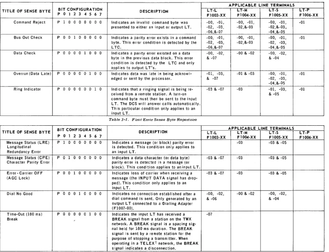
3.2.2.15. Error Sense Bytes (Bytes 54-55)
This field will be set in the event of a unit check or unit exception error to the
J
BCW status field. The execution of a "sense" XIOF will transfer the channel sensebytes to this field of the table prior to the execution of indicator coding. The sense data will only be meaningful in case of a unit check error. Tables 3-1 and 3-2 de-pict the first and second sense byte repertoire.
3.2.3. Output File Control Area
The output file control area is comprised of bytes 56 through 83 of the file control table and is used to control the output or transmit channel of the file. The entries in the output file control area, with the exception of the packet address and buffer address fields, parallel the entries for the input file control area. The packet address is not used in the output file control area, and the buffer address field contents are identical to the contents of the input file control area.
3.2.4. Control Area
This functional area, comprised of bytes 84 through 95, contains the dynamic fields and reference locations of the file control table. Sections 3.2.4.1 through 3.2.4.7 pertain to both input and output files.
3.2.4.1. Current Input Buffer Address (Bytes 84-85)
This field c onta ins the address in the input buffer from which the next data trans-fer will take place to the input data area. The field is set initially prior to the execution of the input function and is updated after each data transfer to the address for the next transfer. The user may access this field during indicator coding to examine the data to be transferred and may modify the address in the least significant 6 bits.
3.2.4.2. Input Move Length (Byte 86)
This field contains the move length for the transfer of data from the buffer area to the input area. The field is set and changed at the same time as the preceding field (bytes 84-85) and may be modified by the use of indicator coding to alter the size of the data transfer. The value in the field is 1 less than the count of char-acters to be moved.
3.2.4.3. Output Move Length (Byte 87)
(
(
)
TITLE OF SENSE BYTE BIT CONFIGURATION DESCRIPTION P 0 1 2 3 4 5 6 7
Command Reject P 1 0 0 0 0 0 0 0 Indicates an invalid command byte was presented to either an input or output LT.
Bus Out Check P 0 0 1 0 0 0 0 0 Indicates a parity error exists in a command byte. This error condition is detected by the LTC.
Data Check P 0 0 001 000 Indicates a parity error existed on a data byte in the previous data block. This error cond ition is detected by the LTC and only appl ies to output L T's.
Overrun (Data Late) POOOOOI
o
0 Indicates data was late in being acknowl·-edged or sent by the processor.Ring Ind icator P 0 0 0 0 0 0 1 0 Indicates that a ringing signal is being re-ceived from a remote station. A turn-on command byte must then be sent to the input LT. The DCS will answer calls automatically. This particular condition only applies to an input LT.
- - - ---_ ..
-Table 3-1. First Error Sense Byte Repertoire
TITLE OF SENSE BYTE BIT CONFIGURATION DESCRIPTION P O l 2 3 4 5 6 7
Message Status (LRE) P 1
o
0 0 0 0 0 0 Indicates a message (or block) parity error Longitudinal is detected. This condition only applies to Redundancy Error an input LT.Message Status (CPE) POI
o
0 0 0 0 0 Indicates a data character (or data byte) Character Parity Error parity error is detected in a message (orblock). This condition applies to an input LT.
Error - Carrier OFF P 0 0 1 000 0 0 Indicates loss of carrier when receiving a (AGC Lock) message (the INPUT DATA signal has
drop-ped). This condition only applies to an input LT.
Dial No Good P 0 0 0 1
o
0 0 0 Indicates no connection established after a dial command is sent. Only generated by an output L T connected to a Dialing Adapter (F1007-00).Time-Out (180 ms) POOOOOI
o
0 Indicates the input L T has received a Break , BREAK Signal from a station on the TWXnetwork. A BREAK signal is a spacing sig-nal held for 180 ms duration. The BREAK signal is sent by a remote station for the purpose of stopping a transm itter. When operating in a TELEXt network, the BREAK signal indicates a disconnection.
Table 3-2. Second Error Sense Byte Repertoire
tTELEX - Trademark of Western Union Telegraph Co.
APPLICABLE LINE TERMINALS L T-L LT-M L T-S
F1003-XX F1004-XX F1005-XX
-00, -01, -00, -01, -00, -01, -02, -03, -02,&-03 -02,&-03, -06,&-07 -04,&-05 -00, -01, -00, -01, -00, -01, -02, -03, -02,&-03 -02, -03, -06,&-07 -04,&-05 -00, -02, -00 & -02 -00, -02, & -07 & -04
-01, -03, -01 & -03 -00, -01, & -07 -02, -03, -04,&-05
-03 & -07 -03 -01, -03, & -05
APPLICABLE LINE TERMINALS
L T-L LT-M LT-S
F1003-XX F1004-XX F1005-XX -03 -03 & -05
-03 & -07 -03 -03 & -05
-03 & -07 -03 -03 & -05
-00, -02, -00 & -02 -00, -02, & -06 & -04
-07
(
L T-P F 1006-XX -01 -01 I -01 -01 LT-P F1006-XXc::
'"tI I "-oJ ()O...
0'1 ac mz z-m< ~:.. :..0 r-o- I - . . ) NO mO
0:0-O~ 0 0 ~ ~ c:O-ZW _ 0 0 0 :..:0--Iw _ 0 0 0 zC l IUP-7816
UNIVAC 9200/9200 11/9300/9300 II 3
GENERALIZED COMMUNICATIONS CONTROL ROUTINE SECTION: PAGE:
3.2.4.4. Current Output Buffer Address (Bytes 88-89)
This field contains the address in the output buffer which is the destination of the latest on imminent data transfer. The field is set at the same time as the preceding field (byte 87) and may be altered in the least significant six bits during indicator coding to change the data to be transmitted. However, aside from including an EOM character and terminating the function, there is no means to avoid transmit-ting 64 characters from the buffer regardless of the number of characters transfer-red to the buffer.
3.2.4.5. RDEVA (Byte 90)
This field is established from the value assigned to the RDEV parameter of the DTFGC macro instruction. The field is referenced in the OPEN and CLOSE coding and remains constant.
3.2.4.6. TDEVA (Byte 91)
This field is established from the value assigned to the TDEV parameter of the DTFGC macro instruction. The field is referenced in the OPEN and CLOSE coding and remains constant.
3.2.4.7. Allocation Code (Bytes 92-93)
This field contains the allocation code established by the SYMB parameter of the DTFGC macro instruction.
NOTE: Bytes 94-95 are currently unassigned but contain the revision number of the DTFGC macro instruction.
3.3. I/O FUNCTION PACKETS
I/O function packets are modules which enable the GCCR to execute input/output functions. The specific function to be performed as well as the control information required to execute that function are contained within the packet.
To initiate a function packet, the user program executes a GET or a PUT macro instruction in which the symbolic name for the function packet is specified. When executed, the GET and PUT macro instructions place a function request onto a function execution list. Once the request is made and the packet listed, control re-turns to the problem program while the completion of the function is pending. In order to determine the status of the function requested, the problem program checks the status bytes of the I/O function packet requested. The STATUS field of the I/O function packet is altered by the control routine as the function passes through to completion.
The format of the I/O function packet is shown in Figure 3-2.
TIME AND I/O FUNCTION HARDWARE STATUS SOFTWARE STATUS
(BYTE 0) (BYTE 1) (