See for yourself
REFERENCE MANUAL
WARNING
This equipment generates, uses, and can radiate radio frequency energy and if not installed and used in accordance with the instruction manual may cause interference to communications. It has been tested and found to comply with the limits for Class A computing devices pursuant to Subpart J
of Part 15 of FCC rules which are designed to provide reasonable protec-tion against such interference when operated in a commercial environment. Operation of this equipment in a residential area is likely to cause inter-ference in which case the user at his own expense will be requ'ired to take whatever measures may be required to correct the interference.
Class A Label DC 010-002 Rev A
o
o
VISUAL TECHNOLOGY INCORPORATED, 540 MAIN STREET, TEWKSBURY, MA 01876
V550
REFERENCE MANUAL
February 1983
VISUAL TECHNOLOGY INCORPORATED, 540 MAIN STREET, TEWKSBURY, MA 01876
SAFETY WARNING
Hazardous voltages 115, 220 VAC and 15 KV DC are present when the, terminal is on, and may remain after power is removed. Use caution when working on internal circuits, and do not work alone.
When handling the cathode ray tube caution is required as the internal phosphor is toxic. Safety goggles and gloves must be used whenever the CRT tube is handled. Should the tube break, skin or eyes exposed to the phosphor, rinse the affected area with cold water and consult a physician.
This terminal is supplied with a cord set which includes a safety ground. Do not use this terminal with an -ungrounded outlet, missing ground pin, or use any adaptor which will defeat the safety ground.
I nsure that power is turned off before connecting or disconnecting the keyboard cable.
VISUAL TECHNOLOGY INCORPORATED, 540 MAIN STREET, TEWKSBURY, MA 01876
TABLE OF CONTENTS
Page 1. INTRODUCTION. . . 1-1
1.1 DESiGN... 1-1
1.2 GLOSSARY OF COMMONLY USED TERMS. . . . .. . . 1-2
2. SPECIFICATIONS. . . .. .. . . .. . . .. 2-1
3. START-UP PROCEDURES. . . . 3-1 3.1 UNPACKING INSTRUCTIONS. . . . 3-1 3.2 INSTALLATION. . . .. . . .. . 3-1 3.3 INTERFACE OPTIONS. .. . . .. . . .. . . 3-1 3.3.1 Data Connectors. . . . 3-3 3.4 WORD LENGTH AND PARITY. . . 3-5 '3.5 SET-UP MODE. . . 3-6
3.6 HOW TO ENTER BASIC SET-UP MODE ... 3-6
3.7 HOW TO CHANGE BASIC SET-UP FEATU RES. . . . 3-7 3.7.1 Line/Local. . . 3-7 3.7.2 Block/Character Mode. . . 3-7
3.7.3 Protect/Unprotect Mode ... 3-8
3.7.4 Click/Silent Mode. . . . 3-8 3.7.5 Normal/Reverse. . . 3-8 3.7.6 Alpha/Graphics Mode. . . 3-8
3.7.6.1 Video Mode Selection ... 3-8
3.7.6.2 Print Page Selection ... '. . . 3-9 3.7.7 Reset ... ". . . 3-9 3.7.8 Menus. . . 3-9 3.7.9 Tabs. . . . .. . . 3-9
3.7.10 Answerback... 3-10
3.8 HOW TO ENTER MENU SET-UP MODE ... 3-11
3.9 HOW TO CHANGE MENU SET-UP FEATU RES. . . . 3-11 3.9.1 Select Editing Menu. . . 3-11
3.9.1.1 Editing Extent Mode ... 3-12
3.9.1.2 Erasure Mode. . . .. . . 3-12
3.9.1.3 Control Representation Mode ... 3-12
3.9.1.4 Auto Tab Mode ... 3-12
3.9.1.5 Auto Wrap Mode ... 3-13
3.9.1.6 Auto New Line Mode. . . 3-13 3.9.2 Select Transmit/ Receive Menu ... ~ . . . 3-13 3.9.2.1 Line Transmit Mode. . . 3-13
3.9.2.2 Guarded Area Transmit Mode ... 3-13
VISUAL TECHNOLOGY INCORPORATED, 540 MAIN STREET, TEWKSBURY, MA 01876 3.9.3 3.9.4 3.9.5 3.9.6 3.9.7 3.9.8
TABLE OF CONTENTS - Continued
3.9.2.5 Transmit Request Mode ... . 3.9.2.6 Function Message Framing ... . Select Commun ication Menu ... .
3.9.3.1 Parity Sense Mode ... .
3.9.3.2 Parity Select Mode ... . 3.9.3.3 Bit Per Character ... .
3.9.3.4 Duplex Mode ... .
3.9.3.5 Transmitter Flow Control Select ... ' ... .
3.9.3.6 Auto XON/XOFF (RCVR) ... .
3.9.3.7 Local Echo Mode ... .
3.9.3.8 2nd Channel Turnaround Mode ... .
3.9.3.9 Transmitter Rate ... .
3.9.3.10 Receiver Rate ... . Select Printer Modes ... . Select Printer Interface ... . Program Message Framing Codes ...•... 3.9.6.1 Message Framing Codes ... . 3.9.6.2 Start of Message Code ... .
3.9.6.3 Area Separator Code ... .
3.9.6.4 First End of Line Code ... .
3.9.6.5
3.9.6.6 3.9.6.7 3.9.6.8
Second End of Line Code ... . First End of Message Code ... . Second End of Message Code ... . Turn Around Control Code ... . Graphics Trailer Code #1 ... . Trailer Code #2 ... . Terminal Status Menu ... .
3.9.7.1 Refresh Rate ... .
3.9.7.2 Screen Saver ... .
3.9.7.3 Status Line ... .
3.9.7.4 Cursor ... .
3.9.7.5 Default Intensity ... .
3.9.7.6 Emulation ... .
3.9.7.7 Keyboard ... .
3.9.7.8 Screen Size ... .
3.9.7.9 XMIT Rate Slow Down ... .
Select Graph ics Operating Parameters ... . 3.9.8.1 Alpha Character Cell Size ... . 3.9.8.2 Space Code Operation ... .
3.9.8.3 Scale Factor ... .
3.9.8.4 Aux Port Mode ... .
3.9.8.5 Printer Type ... " ... . 3.9.8.6 Print I mage Rotation ... . 3.9.8.7 Extended Diagnostics ... . 3.9.8.8 Print I mage Rotation ... . 3.9.8.9 Extended Diagnostics ... .
VISUAL TECHNOLOGY INCORPORATED, 540 MAIN STREET, TEWKSBURY, MA 01876
TABLE OF CONTENTS - Continued
Page 3.10 HOW TO ENTER FUNCTION KEY SET-UP MODE. . . 3-23
3. 10. 1 F unction Key Defi n ition ... 3-24
3.11 HOW TO PROG RAM FUNCTION KEYS ... 3-24
3.11.1 Function Keys . . . 3-24
3.11.2 Function Key Programmable Links ... 3-25
3.11.3 Local Transmit of the Function Key ... 3-25 3.12 PERFORMING A RECALL OPERATION. . . 3-26
3.13 PERFORMING A SAVE OPERATION.. ... .. .... .. .... ... 3-26
3.14 SCREEN BRIGHTNESS ... :... 3-26
4. KEYBOARD CONTROLS. . . .. . . 4-1 4.1 GENERAL. . . . . . 4-1 4.2 KEY FUNCTIONS. . . . 4-1
4.2.1 Numeric Pad Functions ... ,. 4-5
4.2.2 4-5
4.2.3 4-5
4.2.4 Clear Graphics Memory ... 4-5
4.3 EDITING FUNCTIONS. . . .. . . 4-5 4.4 FUNCTION KEYS. . . 4-6
5. ALPHANUMERIC PROGRAMMING ANSI X3.64 ... 5-1
5.1 GENERAL ... ". ... 5-1
5.2 CONTROL CODES. . . 5-1 5.3 CONTROL SEQUENCE FUNCTIONS. . . . . . 5-2
5.3.1 Scrolling Region Command ... 5-4
5.3.2 Cursor Movement Commands. . . . 5-4 5.3.3 Tabbing Commands. . . 5-5
5.3.4 Save/Restore Cursor Command ... 5-6
5.3.5 Report Commands and Sequences . . . 5-6 5.3.6 Select Character Sets Command. . . 5-7
5.3.7 Screen Alignment Command ... 5-8
5.3.7.1 Remote Video Display Modes ... 5-8
5.3.8 Program Function Key Command ... '. . . . 5-8 5.3.9 Erasure Commands. . . . 5-9 5.3.10 Editing Commands. . . . 5-10 5.3.11 Set Communication Control Codes Command . . . 5-11 5.3.12 Video Attribute Commands. . . 5-11
5.3.13 Remote Transmit Command ... 5-12
5.3.14 Reset Command ... 5-12
5.3. 15 Define Area Qual ification Command .. . . 5-12 5.4 MODES. . . 5-13 5.4. 1 Guarded Area Transfer Mode . . . 5-15
5.4.2 Keyboard Action Mode ... 5-15
5.4.3 Control Representation Mode ... 5-15
VISUAL TECHNOLOGY INCORPORATED, 540 MAIN STREET, TEWKSBURY, MA 01876
TABLE OF CONTENTS - Continued
Page 5.4.5 Erasure Mode. . . 5-15 5.4.6 Character .Mode ... ". . . . .. . . 5-15 5.4.7 Multiple Area Transfer Mode ... : . . . . 5-16 5.4.8 Transfer Termination Mode ... . . . 5-16 5.4.9 Line Feed/New Line Mode. . . . 5-16 5.4. 10 Protect Mode . . . 5-16
5.4. 11 Autotab Mode ... 5-17
5.4. 12 Screen Mode. . . . 5-17 5.4.13 Origin Mode. . . 5-17 5.4.14 Autowrap Mode . . . 5-17 5.4.15 Transmit Request Mode. . . 5-17 5.4.16 Line Transmit Mode. . . . 5-17 5.4.17 Screen Size. . . . 5-18
5.5 SELECTED EDITING EXTENT MODE ... 5-18
5.6 SEND STATUS LINE MESSAGE COMMAND ... 5-18
6. GRAPHICS PROGRAMMING ... , . . . 6-1
6.1 GRAPHICS DISPLAY COORDINATES ... 6-1
6.2 DISPLAY COORDINATE FORMAT. . . .. . . 6-2
6.3 SCREEN FORMAT 4010/4014 COMPATIBILITy... 6-8
6.4 CONTROL CODES ... 6-8
6.4. 1 BEL. . . 6-8 6.4.2 BS. . . . . . 6-8 6.4.3 HT. . . 6-8 6.4.4 LF. . . 6-9 6.4.5 VT. . . 6-9 6.4.6 EM. . . 6-9 6.5 ALPHANUMERIC MODE. . . 6-9 6.5. 1 CAN . . . 6-9 6.5.2 Alphanumeric Cursor. . . 6-9
6.6 ALPHAGRAPHICS MODE ... 6-9
6.6.1 CR. . . ... . . . 6-9 6.6.1.1 US. . . 6-10
6.6.1.2 ESC FF ... 6-10
6.6.1.3 SH I FT SET-UP. . . . . . . 6-10
6.6.2 6-10
6.6.3 Alphagraphics Character Size. . . 6-10 6.6.4 Alphagraph ics Margins . . . 6-11 6.7 POINT PLOT MODE. . . 6-11
6.7.1 FS... 6-11
6.8 INCREMENTAL POINT PLOT MODE. . . 6-13 6.8.1 RS ... :'. . . . .. . . 6-13
6.9 VECTOR MODE ... 6-13
6.9. 1 G S ... 6- 13
6.9.2 Line Types . . . 6-17
VISUAL TECHNOLOGY INCORPORATED, 540 MAIN STREET, TEWKSBURY, MA 01876
TABLE OF CONTENTS - Continued
Page
6.9.2.2 Define User Line Styles ... 6-17
6.10 RECTANGULAR DRAW AND FILL... 6-17
6.10.1 ESC/x,y,6 X; 6YX... 6-18
6.10.2 ESC/x, y 6; x, 6y Y . . . .. . . 6-18 6.10.3 Filling Command. . . 6-19 6.10.4 Direction Command. . . . 6-19
6.10.5 6-20
6.11 DATA LEVEL. . . 6-20
6.11.1 6-20
6.12 CROSSHAI R MODE ... 6-20
6.12.1 II ESC SUB or ESC CTRL Z ... 6-21
6.12.2 Load Crosshair . . . 6-21
6.13 INQUiRy... 6-22
6.14 SCALING... 6-23
6.15 BLOCK TRANSFER. . . 6-23 6.15.1 'Address Load ESC" X; Ya . . . 6-23
6.15.2 Data Load ... 6-24
6.15.3 Memory Read ESC "X; Y; . . . 6-24 6.16 GRAPHICS COMMUNICATIONS. .. . . .. . . .. . . 6-25 '
6.16. 1 Handshaking... . . . . . . . . 6-25
6.16.1.2 XON/XOFF... 6-25
6.16.1.3 Status Readback Control .. . . 6-25
6.17 REMOTE PARAMETER SE LECTION ... 6-26
6.17.1 6-26
6.17.2 Aux Port Rec. Data Use Menu #8 ... 6-26
6.18 4014 FONT COMPATIBILITy... 6-27
6.19 CI RCLE AND ARC DRAW. . . 6-27
7. DATA TRANSMISSION. . .. . . .. . . .. . . .. 7-1 7.1 MODES. . . .. . . .. . . 7-1 7.2 MESSAGE FRAMING. . . 7-1 7.2.1 Block Mode Transmission Framing. . . . 7-2 7.2.2 Function Key, Answerback and Status Transmissions ... 7-3 7.2.3 Line Drawing and Foreign Character Sets. . . . 7-4
7.3 HALF/FU LL DUPLEX ... 7-5
7.3.1 Half-Duplex. . . 7-5
7.3.2 F ull- Duplex ... 7-5
7.4 XON/XOFF PROTOCOL. . . . . 7-5 7.5 DTR DATA TERMINAL READY. . . .. . . 7-7
8. VT100 and VT52 COMPATIBILITY.. . .. .. . . ... . ... ... . . . .. . .. .. ... .. . 8-1 8.1 TRANSITIONAL CONTROL CODES. . . 8-1
8. 1. 1 8-1
8.2 VISUAL 300 ENHANCEMENTS IN VT100 AND VT52 MODE. . . 8-1
8.2.1 Programmable Function Keys ... 8-1
8.2.2 Status Line. . . 8-2
VISUAL TECHNOLOGY INCORPORATED, 540 MAIN STREET, TEWKSBURY, MA 01876
TABLE OF CONTENTS - Continued
Page 8.3 VISUAL 550 RESTRICTIONS IN VT100 MODE. . . 8-2
8.3.1 8-2
8.3.2 8-2
8.4 VT100 AND VT52 MODE COMMANDS. . . 8-3 8.4.1 VT100 Mode Commands . . . 8-3 8.4. 1.1 Cursor Next Line . . . 8-3
8.4.1.2 Save Cursor ... 8-3
8.4.1.3 Restore Cursor. . . . 8-3 8.4.1.4 Align Display . . . 8-3
8.4.1.5 Program LE Ds ... 8-3
8.4.1.6 Enter Alternate Keypad Mode. . . 8-3 8.4.1.7 Exit Alternate Keypad Mode . . . 8-4 8.4.1.8 Set Modes. . . . 8-4 8.4.1.9 Reset Modes. . . . 8-4
8.4.1.10 AUTO-REPEAT MODE: ... 8-4
8.4.1.11 EMU LATION MODE: ... 8-4
8.4.1.12 CURSOR KEY MODE: ... 8-4
8.4.1.13 LOCAL ECHO MODE: ... 8-5
8.4. 1 .14 8-5
8.4.1.15 STATUS COMMANDS AND RESPONSES... 8-5
8.4.1.16 REPORT TERMINAL PARAMETERS. . . 8-6 8.4.2 VT52 MODE COMMANDS. . . 8-6 8.4.2.1 Cursor Movement Commands. . . . 8-6
8.4.2.2 Cursor Down ... 8-6
8.4.2.3 Cursor Right. . . 8-7 8.4.2.4 Cursor Left. . . 8-7
8.4.2.5 Cursor Home ... 8-7
8.4.2.6 Reverse Line Feed ... 8-7
8.4.2.7 Cursor Addressing ... 8-7
8.4.2.8 Erase Commands ... . . . 8-7
8.4.2.9 Erase to End-of-Page ... 8-7
8.4.2.10 Enter Graphics 8-7
8.4.2.11 Enter Alternate Keypad Mode . . . 8-8
8.4.2.12 Enter VT100 Mode ... 8-8
8.4.2.13 Identify... 8-8
9. AUXI LIARY INTERFACE. . . .. . . 9-1 9.1 GENERAL. . . .. . . .. . . 9-1
9.2 SER IAL PR INTER INTERFACE ... 9-1
9.3 SERIAL PRINTER SET-UP MODE. .. . . 9-1 9.4 GRAPHIC PRINTER INTERFACE. . . 9-6 9.5 SUMMARY OF GRAPHICS PRINT COMMANDS. . . . .. . . 9-6 9.6 DATA TABLETS. . . 9-9 9.6.1 G.T.C.O. DiGi Pad-5 ... :. . . 9-9
VISUAL TECHNOLOGY INCORPORATED, 540 MAIN STREET, TEWKSBURY, MA 01876
TABLE OF CONTENTS - Continued
Page
9.7 GRAPHIC PRINTERS... 9-10
9.7.1 Anadex. . . . .. . . 9-10 9.7.2 IDS. . . 9-11 9.7.3 Datasouth . . . 9-11 9.7.4 Texprint . . . 9-11 9.7.5 M.P.I.. . . .. . . .. .. . . 9-11 9.7.6 Hi-G.. . . .. . . .. . . . 9-12
10. FIRST LEVE L MAINTENANCE ... '. . . 10-1 10. 1 G ENE R A L . . . 10-1
10.2 TOP COVER ... 10-1
10.2.1 Top Cover Removal .... ... ... ... 10-1
10.3 PRINTED CIRCUIT BOARD REMOVAL AND INSTALLATION... 10-2
10.4 TV MONITOR PCB REMOVAL AND INSTALLATION. . . 10-2
10.5 CRT AND FLYBACK REMOVAL AND INSTALLATION... 10-3
10.6 TV MONITOR ADJUSTMENTS. . . .. . . 10-3 10.7 110/220 VOLT SE LECTION . . . 10-5 10.8 TROUBLESHOOTING V500/550 . . . 10-6 10.9 SE LF TEST. . . 10-7
10.10V500/V550 ... 10-7
APPENDIX I - ALPHANUMERIC CONTROL SEQUENCES ... " '.. . A1-1
APPENDIX II - GRAPHIC COMMANDS. . . A2-1
APPENDIX III - CODE CHARTS... ... A3-1
APPENDIX IV - NUMERIC EQUIVALENT OF ASCII CHART. . . A4-1
APPENDIX V - GRAPHIC RENDITION OF CONTROL CODES ... A5-1
APPENDIX VI - TERMINAL PACKAGING. . . A6-1
APPENDIX VII - MATH SYMBOL SET NO.1. . . A7-1
APPENDIX VIII - MATH SYMBOL SET NO.2.. . ... . . .... .. .... .. .. ... . .. A8-1
APPENDIX IX - VT52 GRAPHICS FONT.. . . .. .. . . A9-1
Figure 3-1 Figure 3-2 Figure 3-3 Figure 3-4 Figure 3-5 Figure 3-6 Figure 3-7 Figure 3-8 Figure 3-9 Figure 3-10 Figure 3-11 Figure 6-1 Figure 6-2 Figure 6-4 Figure 6-5 Figure 6-6 Figure 6-7 Figure 9-1 Figure 9-2 Figure 10-1 Figure 10-2 Figure 10-3 Figure 10-4
Table 3-1 Table 3-2 Table 4-1 Table 4-2 Table 4-3 Table 5-1 Table 5-2 Table 5-3 Table 5-4 Table 5-5 Table 5-6
Table 5-7
Table 5-8
VISUAL TECHNOLOGY INCORPORATED, 540 MAIN STREET, TEWKSBURY, MA 01876
LIST OF FIGURES
Byte Description ... . Basic SET-UP Presentation ... . Tab Set-Up ... -' ... . Answerback Set-Up .. ' ... .' ... . Select Editing Menu ... . Select Transmit/Receive Screen Presentation ... . Select Communication Menu ... . Program Message Framing Codes Screen Presentation ... . Select Terminal Status Screen Presentation ... . Select Graphics Operating Parameters ... . Program Function Keys Screen Presentation ... . Screen Format ... .
Data Sequence Point Plot Mode ... . Incremental Point Plot Directional Characteristics ... . Data Sequence Vector Mode ... . Rectangular Draw ... . Select Printer Modes Screen Presentation ... . Select Printer I nterface Modes Screen Presentation ... . Top Cover Removal ... . PCB Mounting ... .
110/220 Volt Selection ... .
LIST OF TABLES
Initial Settings and Functions for Internal Switches ... . E IA RS232-C Signal Defin itions and Connector Pins ... . Codes Generated by Cursor Positioning Keys ... . Modified Numeric Pad ... . Default Valve of Function Keys ... . Alphanumeric Control Codes ... . Transitional Control Codes ... . I ncremental Cursor Position ing Commands ... . Line Drawing Character Set ... . Summary of Video Attributes and Selective Parameters ... . Selective Parameters Associated With Define Area
Qual ification Com~and ... . Selective Parameters Associated With Set/Reset Mode
Control Seq uences' ... . Selective Parameters Associated With Selected Editing Extent Mode ... .
Table 6-1 Table 6-2 Table 6-3 Table 6-4 Table 6-5 Table 6-6 Table 6-7 Table 7-1 Table 9-1 Table 9-2 Table 9-3
VISUAL TECHNOLOGY INCORPORATED, 540 MAIN STREET, TEWKSBURY, MA 01876
LIST OF TABLES (Continued)
Graphics Control Codes . . . . Alphagraphics Character Size . . . . Margin 1 Location . . . . Line Styles . . . . Selective Parameters Direction Command ... .
6-4 6-8 6-10 6-11 6-17 6-19 6-20 Combinations of Transmission Modes . . . 7-2
VISUAL TECHNOLOGY INCORPORATED, 540 MAIN STREET, TEWKSBURY, MA 01876
1. INTRODUCTION
The VISUAL 550 is a sophisticated, micro-processor based, graphics and alphanumeric display terminal. The terminal employs two independent display memories: alphanumeric and graphics. This architecture allows the VISUAL 550 to deliver full feature graphics with enhanced
alphanumeric functionality.
The VISUAL 550 offers nine operating modes: ALPHANUMERIC, ALPHAGRAPHICS, POINT PLOT, INCREMENTAL PLOT, VECTOR, CROSSHAIR, LOCAL, CHARACTER and BLOCK MODES.
The ALPHANUME RIC functions of the V550 are compatible with the American National Standards Institute (ANSI X3.64) standard for display terminals.
The Alphanumeric functions of the VISUAL 550 may also be selected to be code compatible with the:
Digital Equipment Corporation VT52 and VT100
These emulations are selectable in set-up mode and complete details are contained in section The graphics functions are fully compatible with Techtronix Plot 10® software.
This manual provides programming and application details for the V550. All control sequences and their associated standard are discussed in detail.
1.1 DESIGN
NOTE
For clarity all commands that apply to graphics mode operation are presented with a gray, shade background.
The VISUAL 550 is really two independent display terminals in one.
The alphanumeric "side" is functionally identical to the VISUAL 300 and performs all the functions of a "smart editing" terminal. Alphanumeric data is stored in RAM memory on a character basis. The display matrix for alphanumeric data is 80x34.
The graphics "side" is compatible with Plot 10 software and offers advanced graphics features (primitives) such as Rectangular Draw with fill. Graphics data is stored in RAM memory on a Bit Map basis. The display matrix for graphics data is 768x585.
The VISUAL 5pO employs raster scan technology, thus the CRT is not relied upon to store images. This approach offers many improvements over storage tube technology including a brighter screen, increased speed and selective erase capability.
Since both elements of the display (alphanumeric and graphics, originate from distinct memories they may be intermixed in a nondestructive manner.
The VISUAL 550 is configured using an easy to understand IIMenu Style" Set-Up Mode. These operating parameters are stored in non-vplatile RAM. Most operating parameter may be down loaded from the host.
VISUAL TECHNOLOGY INCORPORATED, 540 MAIN STREET, TEWKSBURY, MA 01876
1.2 GLOSSARY OF COMMONLY USED TERMS
Attribute
Property of a display entity. For example, on a graphics display a line may have the fol!ow-ing attribute - line type.
Absolute Point
An individually addressable position on the display screen, identified by specified X and Y coordinate positions (e.g., X=23, Y=32).
Absolute Vector
A line segment drawn from the current beam position to an absolute point. The end
coordinates are defined in Absolute Units relative to the origin of the I MAG E DE FIN ITI ON A R EA. Contrast relative vector.
Addressability
The smallest discrete unit at which a display element can be defined and to which the hardware responds. The addressability of the V550 image definition area is one part in
1024 and of the viewing area is one part in 768. The smallest addressable display element is sometimes called a Raster Unit (R.U.).
Addressable Point
Any position is the Viewing Area to which the CRT beam may be directed. These positions are specified by COO R D I NATES. Such addressable positions are finite in number, and form a discrete grid over the VIEWING AREA. In a matrix display such as the PLASMA PAN E L, and Addressable Point and Resolution are iqentical.
Basic Vector
In V550, a vector in one of the eight major directions (horizontal, vertical and 45° to these di rections).
Blink
A hardware mode where the displayed information "blinks", i.e., turn on and off, typically twice a second; usually to attract the attention of the operator as with a warning message (also known as FLASH).
Character Generator
A hardware or firmware option which takes character data stored in ASCII character format and causes the appropriate deflections and or intensifications on the CRT to cause the corresponding character images to appear on the screen.
Contrast
VISUAL TECHNOLOGY INCORPORATED, 540 MAIN STREET, TEWKSBURY, MA 01876
Coordinate
A positional reference on the.display image relative to an origin. In a display system the hardware interprets coordinates in the raster units, whereas in a program user defined coordinates may be used.
Cursor
A flashing underscore or symbol displayed on a screen. It is usually positioned where the next alphanumeric character will be displayed, or other data entry may take place. May be moved by the driving computer, or the operator through keypress, or other operator input devices.
Data Tablet
A graphic input device which encodes X-Y data from a hand held stylus. The portion of the stylus on the tablet surface may be interrogated under program control or may be continuously input. Most writing tablets provide the coordinate information by sensing signals from parallel sets of X and Y wires under the surface. Another form of writing tablet is the sonic variety which the sound from sparks is received by microphones at the edge of the tablet.
Function Keypad
A portion of an alphanumeric keyboard, typically with 8 keys, used to invoke control functions, e.g., move cursor left, right, up, down. Sometimes called Function Keyboard, and may be separate from alphanumeric keyboard.
Graphic
Adjective. Synonomous with Display (adj.) and Graphical. Usually refers to those devices that draw lines and points.
Hard Copy
A permanent copy of a DISPLAY IMAGE.
INTENSITY
Strictly, the absolute luminosity of brightness of an image on the display screen.
Line Type
The type of line used to display vectors on the screen.
Mode
VISUAL TECHNOLOGY INCORPORATED, 540 MAIN STREET, TEWKSBURY, MA 01876
Monitor
Usually refers to the physical CRT unit and housing used in graphic display systems.
Phosphor
The chemical coating on the inside face of a CRT which emits visible light when energized by an electron beam.
Pixel
A single picture element, a dot.
Primitive
One of the fundamental graphics entities. A primitive is one vector (relative, absolute, etc.) a point, a text string. Primitives are the smallest definable objects in a display processor's instruction set.
Raster Scan
A technique for generating or recording an image with an intensity controlled, line-by-line sweep across the Display Surface.
Raster Unit
The horizontal or vertical distance between two adjacent addressable points on a CRT Display. Analogous to Plotter Step Size.
Refresh Rate
The rate at which a Display is Regenerated.
Relative Vector
A vector whose end points are defined with respect to a relative origin.
Resolution
The smallest distance between two display elements which can be perceived as two distinct elements by the viewer.
Scaling
A Transformation Function that alters one or more Display Elements by multiplying their Coordinates by constant values. The effect of Scal ing is to change their size or shape in a graphics system, either in the Display Image, in the graphics data base or in both.
Scale Factor
VISUAL TECHNOLOGY INCORPORATED, 540 MAIN STREET, TEWKSBURY, MA 01876
Screen Size
The size of a cathode ray tube is the diameter of the tube outside of its housing, or for a non-round tube the length of the maximum diagonal. The screen size sometimes refers to the dimensions - length and breadth - after the CRT has been mounted in its housing. Because of tube mounting and deflection limits, the VIEWING AREA may be less than the Screen Size.
Scrolling
Conventional scrolling is the movement of an image usually a block of text up the screen to allow the display of a new line at the bottom.
Selective Erase
Removal of one or more specified Display Elements, Display Entities, or Display Groups without affecting the remainder of the Display I mage.
Subpicture
An entity defined by grouping together several primitive definitions. A subpicture is
analogous to a computer subroutine and is used for the same reasons - primarily modularity and efficiency. By referencing a subpicture, images can be repeated without having to respecify the primitives included in the subpicture definition.
Text Mode
The manner in which text is displayed, e.g., normal, italics, subscript, superscript, etc.
Vector
As in the classical definition of vectors, graphic vectors possess the attributes of magnitude and direction and are generally defined relative to the "current beam positions."
Vector Generator
A function generator which in hardware takes vector definition data, typically X and Y beam displacements or end point coordinates, and draws a line directly on the screen.
Vector Type
The specification of the vector appearance. For example, V550 has vector types: solid, dashed, short dashed, dot-dash.
Viewing Area
VISUAL TECHNOLOGY INCORPORATED, 540 MAIN STREET, TEWKSBURY, MA 01876
Windowing
The visual effect achieved by the apparent movement of a Viewing Area across a larger image area.
Window
VISUAL TECHNOLOGY INCORPORATED, 540 MAIN STREET, TEWKSBURY, MA 01876
Display Format
34 x 80 Characters Selectable to 24 x 80
Graphics Display t' ,. , > . ,,_
Format
, 768x
585:PixelsDisplay Memory
One Page 2720 Characters One ,Page 449,280Pi><'els
CRT Size
14" Measured Diagonally
Image Size
9.0 x 6.75 Inches
Character Cell Size
9 x 15 Alpha
l(l x1
c5G'raPhics,qr ' ,; tOx,;17;
G
raptHcsqr6
,x, lh(5):aphiGs '
Character Generation
Dot Matrix 7 x 11 Alpha
',~1'x.
'r
1~6raJ:)hics,.: ~, ~: '.. c, C i: { J".., C,' Screen AttributesNormal and Reverse
Video Attributes
Normal, Blink, Blank, Reverse, Bold, Underline
Gr:~pJ:jic$:
Attrlbqies\ ' n ,
, Beverse,
$
Line
StyleS,S
Fi.IJS~Yles
Line
Styles
No
rm at
',D.otted,
Qot-
Dasb,Shprt.oa~tJ, .longD~sh·i Us~r#1',
2. SPECIFICATIONS
Fill Styles.
Solid, Gr~y, SloP~,L1pLeft,Slope>Up: Right, ,Horizol'}ta.I,l:jn:es,V~r~icle~,h'ir1E~s, Slant Cross HatGh, VertipleGross H~tch .
Logical Attributes
Protect, Unprotect
Communication Interface
RS232C or 20MA '
Transmission Speed
50 to 19.2K Baud
Independent transmit and receive rate
Parity
Odd, even, none, mark, space
Communication Modes
Full duplex, half duplex, local, character or block
Message Framing
User defined: SaM, AS, FEOl, SEal, FEOM, SEaM, TACC, TRAI lER 1, TRAI lER 2
Status Line
34th Line of display 48 Character host message
Line/local, keyboard lock, edit mode, row, col, status
Keyboard
Detachable 95 key, ASCII compatible, typewriter style, auto repeat, keycl ick, "N" Key rollover, numeric pad, caps lock, sculptured and matted keys.
Function Keys
VISUAL TECHNOLOGY INCORPORATED, 540 MAIN STREET, TEWKSBURY, MA 01876
Cursor Movement Keys
Alpha mode - up, down, left, right, home, CR, LF, Tab
Graphics Mode -Horizontal, vertical, and 45° relative toeach,home
Fast Move - 8 Pixel incremental move
Scrolling
Jump, definable scrolling region, up or down
Tabulation
80 Programmable stops, left or right, tabbing by field.
Editing Functions
I nsert character, delete character, insert line, delete line,
Transmission Modes
Line, page, batch
Erase Functions
All, Line, field or page. From or to cursor location
Graphics Modes
Alphagraphics, pointplot, incremental point plot, vector, crosshair, memory load, memory read
Graphics Data Levels
Dots on, dots off, .dots complimented, dots replaced
Graphics Scaling
.75 1
1 : 1
Alpha Graphics Scaling
1 X, 2X, 3X, 4X
Primitives
Rectangular draw, rectangular fill, eight line styles, eight fi II styles, circle, arc draw
Indicators
Caps on LED
Audible Indicators
User enabled keycl ick, tone on receipt of bel code, or at col 72 if enabled
Self Test
Automatic on, power on, audible tone indicates OK
Character Set
128 ASCII Characters, 16 Line Drawing Character, 16 control code representation characters
Auxiliary Interface
Buffered Printer Port, independent transmit/receive, RS232C or 20MA
Cursor
Alphanumeric -Blinking or solid block
Alphagraphics - Underline Crosshair- Full Screen Crosshair
External Controls
Power on/off switch
Intensity
0 0
savable in non volatile RAM
Emulation Protocol
ANSI 3.64, VT52GJ, VT1 DOC!>
VISUAL TECHNOLOGY INCORPORATED, 540 MAIN STREET, TEWKSBURY, MA 01876
Input Voltage
115/240 V AC + 10%, -20% 50/60 Hz
Weight
371bs
tl
[
\17.25 (438,15)
18.65 (473.71)
16.25 (412,75)
14.40 (365,76)
I
III ~
_J
1.96 (49.78)
?I~~)
LEGEND = .(~D6~M)'I ,
VISUAL TECHNOLOGY INCORPORATED, 540 MAIN STREET, TEWKSBURY, MA 01876
3.
START-UP PROCEDURES
This chapter contains the information necessary to unpack, install and set up the VISUAL 550 terminal.
3.1 UNPACKING INSTRUCTIONS
The VISUA L 550 is packed in a reinforced carton containing the following items.
Monitor Keyboard AC Power Cord Keyboard Cable Reference Manual
Appendix VI shows the packing used with the VISUAL 550. To unpack the terminal from the shipping container use the procedure outlined in Appendix XI.
3.2 INSTALLATION
Refer to Chapter 2 specifications for external dimensions and environmental considerations.
/
a. Place the monitor on a level surface. A desk or table is satisfactory. However, most operators prefer a lower surface such as a typewriter stand.
b. Connect the keyboard to the monitor using the coiled cable provided.
WARNING
The VISUAL 550 can be wired for 120/240 VAC and 50/60 Hz power. The V550 Maintenance Manual details the conversion steps for each.
c. Plug the terminal into a compatible ac power source. d. Power on the terminal.
e. The terminal will perform initial power on tests. A successful power on test will be indicated by a short audible tone. If the power on tests are unsuccessful refer to Chapter 10 First Level Maintenance.
3.3 INTERFACE OPTIONS
The VISUAL 550 is designed to exchange data through several approved hardware protocols.
VISUAL TECHNOLOGY INCORPORATED, 540 MAIN STREET, TEWKSBURY, MA 01876
The appropriate interface protocol is selected via a row of 8 miniature dip switches located on the main PWB. Table 3-1 summarizes the function of each switch.
NOTE
The VISUAL 550 is shipped from the factory with the RS232 interface selected.
TABLE 3-1
INITIAL SETTINGS AND FUNCTIONS FOR INTERNAL SWITCHES
Switch Initial
Number Setting OFF ON Comments
3 OFF
6 OFF E I A Interface Current Loop
Passive Current Interface
8 OFF Loop Interface Active Cu rrent Receive
(Exterior Current Loop Interface
Source) (V330 Current
Source)
7 OFF E I A I nterface or Current Loop Receive
Current Loop I nterface Passive Active
2 OFF Passive Current Active Cu rrent X-mit
Loop Interface Loop Interface
1 OFF E IA Interface or Current Loop X-mit
Current Loop Interface Passive
Active
5 OFF Pin#190nEIA Pin #19 Switches For EIA
Interface Appropriately Secondary
Disconnected Channel
4 ON Pin #11 on EIA Pin #11 Switches For Bell 202
Interface Appropriately Secondary
VISUAL TECHNOLOGY INCORPORATED, 540 MAIN STREET, TEWKSBURY, MA 01876
Examples of Typical Settings
1. Passive Current Loop Interface; Switches 1,6,7 ON 2. Active Current Loop Interface; Switches 2,6,8 ON
3. EIA RS232/CCITT V24, Switch 5 ON (all other switches OFF) 4. Bell 202 I nterface, Switch 4 ON (All other switches OF F)
Other cummunication interface features include:
· . Local copy capability for applications requiring "Echoing" of transmitted data. · . 16 data rates ranging from 50 to 19,200 baud
· . Odd, even, mark, space or no parity. · .7 or 8 bit ASCII Code (See Figure 2-1) · . Half or full duplex
· . Secondary channel
· . User programmable non-volatile message framing · . User programmable non-volatile answer back
· . DTR hardware flow control
3.3. 1 Data Connectors
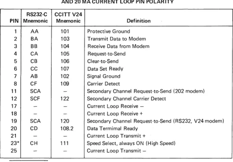
Data connections to the VISUAL 550 are provided through two female 25 pin EIA con-nectors located on the rear of the terminal. The pin definitions of these concon-nectors are summarized in Table 3-2.
The connector labeled modem is for connection to the host or data set.
PIN
1 2 3 4 5 6 7 8 11 12 17 18 19 20 21 23* 25
VISUAL TECHNOLOGY INCORPORATED, 540 MAIN STREET, TEWKSBURY, MA 01876
TABLE 3-2
EIA RS232-C SIGNAL DEFINITIONS AND CONNECTOR PINS, AND 20 MA CURRENT LOOP PIN POLARITY
RS232-C CCITT V24
Mnemonic Mnemonic Definition
AA 101 Protective Ground
BA 103 Transmit Data to Modem
BB 104 Receive Data from Modem
CA 105 Request-to-Send
CB 106 Clear-to-Send
CC 107 Data Set Ready
AB 102 Signal Ground
CF 109 Carrier Detect
SCA - Secondary Channel Request-to-Send (202 modem)
SCF 122 Secondary Channel Carrier Detect
- - Current Loop Receive
-- - Current Loop Receive
+
SCA 120 Secondary Channel Request-to-Send (RS232, V24 modem)
CD 108.2 Data Termimal Ready
- - Current Loop Transmit
+
CH 111 Speed Select, always ON (High Speed)
- - Current Loop Transmit
-*Pin 23 is used on some dual-speed modems to select speed. This VISUAL 550 always has this signal ON. If low speed operation of the dual-speed modem is desired, it is necessary to "float" pin 23 (extract pin 23 from the modem cable at one end).
VISUAL TECHNOLOGY INCORPORATED, 540 MAIN STREET, TEWKSBURY, MA 01876
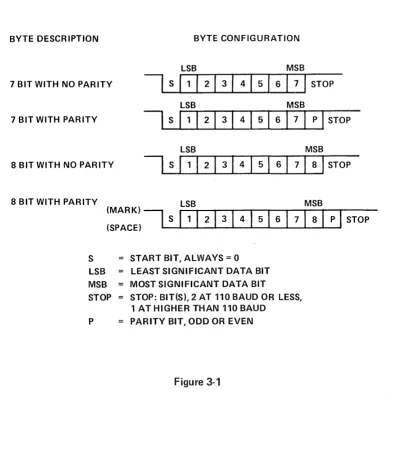
3.4 WORD LENGTH AND PARITY
The VISUAL 550 may be configured to 7 or 8 bit ASCII code and mark, space, odd, even or no parity. The byte description for each configuration is shown in Figure 3-1.
BYTE DESCRIPTION BYTE CONFIGURATION
LSB MSB
7 BIT WITH NO PARITY
I
S (1 1 2 1 3 I 4 I 5 I 6 IiJ
STOPLSB MSB
7 BIT WITH PARITY
I
S11
I
21
3I
4I
5I
6I
7I
PI
STOPLSB MSB
8 BITWITH NO PARITY
I
SI
1I
2I
3I
4I
5I
6I
7I
8I
STOP 8 BIT WITH PARITY ( ) LSB MSB(:P:::I
I
S
11 1
21
3
1
41
5
1
6
1 71 81
P
1
STOP
S START BIT, ALWAYS = 0 LSB LEAST SIGNIFICANT DATA BIT MSB MOST SIGNIFICANT DATA BIT
STOP STOP: BIT(S), 2 AT 110 BAUD OR LESS, 1 AT HIGHER THAN 110 BAUD
P PARITY BIT, ODD OR EVEN
VISUAL TECHNOLOGY INCORPORATED, 540 MAIN STREET, TEWKSBURY, MA 01876
3.5 SET UP MODE
The VISUAL 550 employs a sophisticated, easy to use ME NU-STYLE parameter selection method that allows the user to define the terminals' characteristics from the keyboard in single keystrokes. The terminals' features and modes are selected and stored in a special mode called SET-UP MODE.
Terminal features and modes are stored (remembered) in a non-volatile ram memory. Once the desired parameters have been selected the terminal will function per the new configura-tion. The new configuration will be considered temporary, unless a save operation is per-formed, and a subsequent recall or power on operation will return the terminal to the previously saved characteristics. If the save operation is performed, the new configuration is considered permanent and will be recalled on subsequent recall or power up operations. A reset operation will set the terminal parameters to the previously saved state.
Set-up mode is divided into three groups; basic, menu, graphics and function key, set-up modes.
In the basic set-up mode the user selects status line modes, columnar tab stops, answer back message, reset function or menu mode. Each basic set-up mode feature is described in Section 3.7.
In menu set-up mode the user selects up to eight (8) programming menus.
Select Editing Menu
Select Transmit/Receive Menu Select Communicati.on Menu Select Printer Menu
Select Printer I nterface Menu Program Message Framing Codes Select Terminal Status
Select Graph ics Parameters
Each MENU SET-UP MODE is described in Section 3.9.
In function key set-up mode the user programs the twelve (12) function keys. The function key set-up mode is described in Section 3.10.
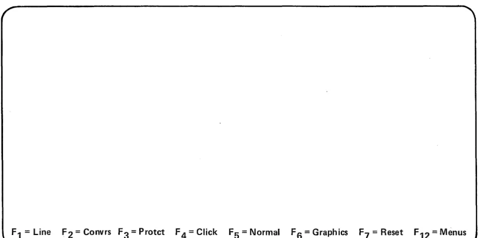
3.6 HOW TO ENTER BASIC SET-UP MODE
VISUAL TECHNOLOGY INCORPORATED, 540 MAIN STREET, TEWKSBURY, MA 01876
F1
=
Line F2=
Convrs F3=
Protct F 4=
Click F5=
Normal F6=
Graphics F7=
Reset F12=
MenusFigure 3-2. Basic SET-UP Presentation
3.7 HOW TO CHANGE BASIC SET-UP FEATURES
Once basic set-up mode has been entered any basic set-up feature may be changed from the key-board by depressing a single key. Some basic set-up features may also be changed by the host computer via control sequence function.
3.7.1 Line/Local (F 1)
On line or local operation is selected by depressing the
B
key on the keyboard. Subsequent depressions of the8
key alternates between Local and On· Lineoperation.
When On Line, the terminal may send or receive data from the host computer. When in Local (Off Line) the terminal is electrically disconnected from the host computer. Any data entered at the keyboard is looped back through the terminal receiver and displayed on the screen.
3.7.2 Block/Character Mode (F2)
Block of Character mode is selected by depressing the
B
key on the keyboard. Subsequent depressions of the8
key alternates between Character Block mode.VISUAL TECHNOLOGY INCORPORATED, 540 MAIN STREET, TEWKSBURY, MA 01876
3.7.3 Protect/Unprotected Mode (F3)
Protect or Unprotect mode is selected by depressing the key on the keyboard.
Subsequent depressions of the
6
key alternates between Protect and Unprotectmode.
This feature determines whether Area Attributes Codes (AAC) defining protected fields are recogn ized or not. See Section 5.4.10.
3.7.4 Click/Silent Mode (F4)
Click or Silent mode is selected by depressing the key on the keyboard.
Subsequent depressions of the
a
key alternates between Silent and Click mode. When Click is. selected, an audible key click tone will be generated by the VISUAL 550 for each code generating key depression.3.7.5 Normal/Reverse (F5)
Normal or Reverse Screen mode is selected by depressing the keyboard.
key on the
Subsequent depressions of the key alternates between Reverse and Normal Screen mode.
Normal mode characters are formed by white dots on a black background. Reverse mode characters are formed by black dots on a wh ite background.
3.7.6 Alpha/Graphics Mode (F6)
Alphanumeric or Graphics Display mode is selected by depressing keyboard.
key on the
Subsequent depression of the key steps between alphanumeric, graphics, BOTH
and Auto display modes. See Section 6.
3.7.6.1 Video Mode Selection (F6)
The V550 can display either the ALPHANUMERIC video or the GRAPHICS video
separ-ately or simultaneously. Depressing
a
will select which video presentation will bedisplayed when SETUP Mode is exited. There are four choices:
AUTO: The video presentation will be either the ALPHANUMERIC or GRAPHICS
depending upon which is presently IIreceiving" the incoming data stream. GRAPH I CS: The GRAPH I CS video presentation wi II always be visible. The
VISUAL TECHNOLOGY INCORPORATED, 540 MAIN STREET, TEWKSBURY, MA 01876
ALPHA:
BOTH:
The ALPHANUMERIC video presentation will always be visable. The GRAPHICS presentation will only be visible if the incoming data stream is being "received" by the GRAPHICS presentation.
Both the ALPHANUMERIC and GRAPHICS presentations will always be visable.
3.7.6.2 Print Page Selection
The state of video mode selection also determines which video presentation is output to the printer upon a print page command.
Alpha or Auto: Outputs the alphanumeric memory to the printer.
Graphic or Both: Outputs the graphic memory to the printer.
3.7.7 Reset (F7)
Depressing key causes the VISUAL 550 to execute a reset command.
The reset operation has the same effect as powering-down then powering-up the terminal and is used to run the self test. The reset command, however, returns the terminals' parameters to their IIsaved" state. This operation clears the screen of all data.
3.7.8 Menus (F12)
Depressing key causes the terminal to enter the first of eight menus.
WARNING
Entering menu set-up mode clears the screen of all alphanumeric data.
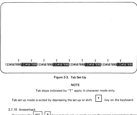
3.7.9 Tabs
r:;--,
Depressing the shift
~
keys in basic set-up mode cause the screen presentation shownin Figure 3-3 to be displayed.
The location of each columnar tab stop is indicated by a high intensity liT" in Figure 3-3.
All tab stops may be cleared by depressing the shift tab key. To set or clear tab stops on an individual basis the following procedure is used:
1. Position the cursor, using tab, or return, to the tab stop to be set or cleared.
2. Depress the
[2J
key to set/clear the tab stop at the cursor location.Subsequent depressions of the
[2J
key will alternately clear/set the tab at the cursorVISUAL TECHNOLOGY INCORPORATED, 540 MAIN STREET, TEWKSBURY, MA 01876
T T T T T T T T T
1234567890ititIt1;tI:pnn 234567890Ititl.1;ij:Fnt1234567890Ititl.1;tI*un
234567890Irwf.~*t"·~'!r.*ll:'Ii~*:r..mFigure 3-3. Tab Set-Up
NOTE
Tab stops indicated by liT" apply in character mode only.
Tab set up mode is exited by depressing the set-up or shift
~
key on the keyboard.3.7.10 Answerback
Depressing the
B 0
keys in basic set-up mode causes the screen presentation shown ini Figure 3-4 to be displayed.The answerback message of up to 32 characters is programmed at cursor location by typing a user defined delimiter followed by the text of the message and ended with the defined delimiter.
NOTE
The delimiter may be an ASCII character not used in the message. If any control codes are used as part of the message, the code is displayed as in control representation mode. Delimiters are exclusive of the 32 character limit.
EXAMPLE:
/
THIS IS VISUAL 550/
I
I
VISUAL TECHNOLOGY INCORPORATED, 540 MAIN STREET, TEWKSBURY, MA 01876
When the ending delimiter is typed or upon exceeding 32 characters the terminal exits answerback mode and returns to the basic set-up mode. The answerback message is con-sidered temporary unless a save operation is performed.
ANSWER BACK =
Figure 3-4. Answerback Set-Up
3.8 HOW TO ENTER MENU SET-UP MODE
The menu set-up mode is entered by depressing the set-up key followed by the
key. When the menu set-up mode is entered, the screen will display the first of eight set-up
menus (Figure 3-4), Subsequent depressions of the
8
key causes the terminal tostep through the eight available menus. Menu set-up mode is exited by depressing the set-up key on the keyboard.
WARNING
Entering menu set-up mode clears the screen of all ALPHANUMERIC data.
3.9 HOW TO CHANGE MENU SET-UP FEATURES
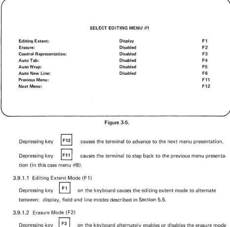
3.9.1 Select Editing Ment:!
VISUAL TECHNOLOGY INCORPORATED, 540 MAIN STREET, TEWKSBURY, MA 01876
Editing Extent: Erasu re:
Control Representation: Auto Tab:
Auto Wrap: Auto New Line: Previous Menu: Next Menu:
SELECT EDITING MENU
#1
Display Disabled Disabled Disabled Disabled DisabledFigure 3-5.
F1 F2
F3
F4 F5 F6 F11 F12
Depressing key
~
causes the terminal to advance to the next menu presentation. Depressing keyB
causes the terminal to step back to the previous menupresenta-tion (in this case menu #8).
3.9.1.1 Editing Extent Mode (F 1)
Depressing key
B
on the keyboard causes the editing extent mode to alternate between: display, field and line modes described in Section 5.5.3.9.1.2 Erasure Mode (F2)
Depressing key
B
on the keyboard alternately enables or disables the erasure modedescribed in Section 5.4.5.
3.9.1.3 Control Representation Mode (F3)
Depressing key
B
on the keyboard alternately enables or disables the control repre-sentation mode described in Section 5.4.3.3.9.1.4 Auto Tab Mode (F4)
VISUAL TECHNOLOGY INCORPORATED, 540 MAIN STREET, TEWKSBURY, MA 01876
3.9.1.5 Auto Wrap Mode (F5)
Depressing key
G
on the keyboard alternately enables or disables the auto line feedmode described in Section 5.4.5.
3.9.1.6 Auto New Line Mode (F6)
Depressing key
~
on the keyboard alternately enables or disables the auto new linemode described in Section 5.4.9.
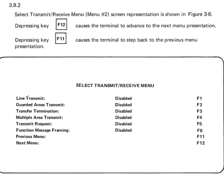
3.9.2
Select Transmit/Receive Menu (Menu #2) screen representation is shown in Figure 3-6.
Depressing key /
F12/
causes the terminal to advance to the next menu presentation. Depressing key8
presentation.
Line Transmit:
Guarded Areas Transmit: Transfer Termination: Multiple Area Transmit: Transmit Request:
Function Message Framing: Previous Menu:
Next Menu:
causes the terminal to step back to the previous menu
SELECT TRANSMIT/RECEIVE MENU Disabled
Disabled Disabled Disabled Disabled Disabled
Figure 3-6. Select Transmit/Receive Screen Presentation
3.9.2.1 Line Transmit Mode (F 1)
F1 F2 F3 F4
F5
F6 F11 F12
Depressi ng key
B
on the keyboard alternately enables or disables the line transmit mode described in Section 5.4.17.VISUAL TECHNOLOGY INCORPORATED, 540 MAIN STREET, TEWKSBURY, MA 01876
Depressing key on the keyboard alternately enables or disables the guarded area
transfer mode described in Section 5.4.1.
3.9.2.3 Transfer Termination Mode
Depressing key
B
on the keyboard alternately enables or disables the transfertermination mode described in Section 5.4.8.
3.9.2.4 Multiple Area Transmit Mode (F4)
Depressing key
B
on the keyboard alternately enables or disables the multiple areatransmit mode described in· Section 5.4.7.
3.9.2.5 Transmit Request Mode (F5)
Depressing key
GJ
on the keyboard alternately enables or disables the transmitrequest mode described in Section 5.4.6.
3.9.2.6 Function Message Framing (F6)
Depressing key
B
on the keyboard alternately enables or disables function keymessage framing.
When enabled function key transmission will be framed as defined in Section 7.
3.9.3
Select Communication Menu (Menu #3) screen presentation is shown in Figure 3-7.
Depressing key
8
causes the terminal to advance to the next presentation, Depressing keyB
causes the terminal to step back to the previous menup resentati on.
3.9.3.1 Parity Sense Mode (F 1 )
VISUAL TECHNOLOGY INCORPORATED, 540 MAIN STREET, TEWKSBURY, MA 01876
Parity Sense: Parity Select: Bits per Character: Duplex
Auto Xon/Xoff (XMTR): Auto Xon/Xoff (ACUR):
Local Echo
Second Channel Turnaround: Transmitter Rate:
Receiver Rate: Previous Menu Next Menu
SELECT COMMUNICATION MENU
Disabled N/A 7
Full Disabled Disabled Disabled Code 9600 9600
Figure 3-7. Select Communication Menu
3.9.3.2 Parity Select Mode (F2)
F1 F2 F3 F4 F5 F6 F7 F8 F9 F10 F11 F12
When parity sense mode is disabled depressing key action.
on the keyboard causes no
When parity sense mode is enabled then depressing key
the terminal to alternately select odd or even parity.
3.9.3.3 Bits Per Character (F3)
B
on the keyboard causesDepressing the key
EJ
on the keyboard causes the terminal to alternately select7, 8 bit mark or 8 bit space.
NOTE
VISUAL TECHNOLOGY INCORPORATED, 540 MAIN STREET, TEWKSBURY, MA 01876
3.9.3.4 Duplex Mode (F4)
Depressing key
6
on the keyboard alternately selects full of half. Duplex modeoperation is defined in Section
3.9.3.5 Transmitter Flow Control Select (F5)
Depressing key
8
on the keyboard alternately selects the flow control to beXON/XOF F, DTR busy or none. Refer to section 7.5 for details.
3.9.3.6 Auto XON/XOFF (RCVR) Mode (F6)
Depressing key
a
on the keyboard alternately enables or disables auto XON/XOF Fmode as described in Section 7.4.
3.9.3.7 Local Echo Mode (F7)
Depressi ng key
G
on the keyboard alternately enables or disables local echo mode. The local echo feature provides for an automatic "echoing" of transmitted data back to the screen. If an echoing of transmitted data is not desired, the terminal is used for half duplex, or the host computer or modem provides an echo, this feature should be disabled.3.9.3.B Second Channel Turnaround Mode (FB)
Depressing key
~
on the keyboard causes the terminal to alternately select codeor second channel mode.
This feature applies to half-duplex operation only and determines whether a turnaround
control code or secondary channel wi II be used for line turnaround.
If the turnaround feature selects a turnaround control code, the turnaround control code may be any ASCII character and may be selected remotely.
3.9.3.9 Transmitter Rate (F9)
Depressing key
B
on the keyboard causes the terminal to step through the selectableVISUAL TECHNOLOGY INCORPORATED, 540 MAIN STREET, TEWKSBURY, MA 01876
3.9.3.10 Receiver Rate (F10)
Depressing key
I
FlO]
on the keyboard causes the terminal to step through theselectable receiver baud rates.
3.9.4 Select Printer Modes (Menu #5)
Please refer to Section 8.0 buffered printer interface.
3.9.5 Select Printer Interface (Menu #6)
Please refer to Section 8.0 buffered printer interface.
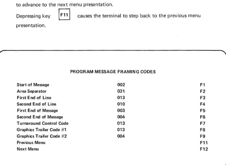
3.9.6 Program Message Framing Codes (Menu #7)
Screen presentation is shown in Figure 3-8 depressing key causes the terminal
to advance to the next menu presentation.
Depressing key
El
causes the terminal to step back to the previous menupresentation.
Start of Message Area Separator First End of Line Second End of Line First End of Message Second End of Message Turnaround Control Code Graphics Trailer Code #1 Graphics Trailer Code #2 Previous Menu
Next Menu
PROGRAM MESSAGE FRAMING CODES
002 031 013 010 003 004 013 013 004
Figure 3-8. Program Message Framing Codes Screen Presentation
3.9.6.1 Message Framing Codes (F1-F7)
F1 F2 F3 F4 F5 F6 F7
F8
F9 F11 F12
VISUAL TECHNOLOGY INCORPORATED, 540 MAIN STREET, TEWKSBURY, MA 01876
To program a particular framing code from the program message framing codes menu, depress the appropriate function key (F 1 through F7). The selected code is erased and the the cursor moves to the least significant digit of the code. The new code is entered at the
cu rsor position and wi II 'sh ift left for each digit entered. The entry is completed either by depressing the selected function key or by depressing the enter key. Depressing enter key causes the cu rsor to advance to the least sign ificant position of the next code.
Example: To program the first end of line code ASCII character CR (013)10
1. Depress key
GJ
selecting First End of Line (FEOL). 2. Enter 0 1 33. Depress key
B
A message framing code may be anyone of 128 ASCII codes expressed as a decimal number. If a decimal number in excess of 128 is entered, the terminal will reject the entry and the cursor will return to the least significant position of the selected code.
3.9.6.2 Start of Message Code (F 1)
The start of message code (SOM) precedes all block transmissions from the VISUAL 300 including function key transmissions and status transmissions. Receipt of a start of message code will lock the keyboard.
3.9.6.3 Area Separator Code (F2)
The area separator code (AS) is inserted into all block transmission data streams to separate each unprotected area transm itted. I f protected data is transm itted, the (AS) is not used.
3.9.6.4 First End of Line Code (F3) and Second End of Line Code (F4)
The First End of Line code (FEOL) and the Second End of Line code (S~OL) are inserted into block transmission data streams to signify the end of data on each line.
3.9.6.5 First End of Message Code (F5) and Second End of Message Code (F6)
The First End of Message code (F EOM) will terminate all block transmissions from the VISUAL 550 including function key transmissions and status transmissions. Receipt of either a SEOM or FEOM.will clear a keyboard locked condition previously caused by receipt of the start of message code.
3.9.6.6 Turn Around Control Code (F7)
The Turn Around Contrdl Code(TACC) is used to switch the VISUAL 550 from a receive state to a transmit state (or vice versa) when in character mode half duplex operation. When received by the terminal the TACC causes the terminal to switch from the receive state to the transm it state. When transm itted by the term ina I the T ACC causes the term inal to switch from transm it state to receive state.
VISUAL TECHNOLOGY INCORPORATED, 540 MAIN STREET, TEWKSBURY, MA 01876
3.9.6.7 Graphics Trailer Code #1 (FS)
The Trailer Code #1 is appended to the transmission of blocks of graphic data.
3.9.6.S Trailer Code #2 (F9)
The Trailer Code #2 is appended to the transmission of blocks of graphic data.
DEFAULT CODES MESSAGE FRAMING
Message Framing Codes
Default Code
Type in Decimal
SOM 002
AS 031
FEOl 013
SEOl 010
FEOM 003
SEOM 004
TACC 013
TRAI lER #1 013
TRAI lER #2 004
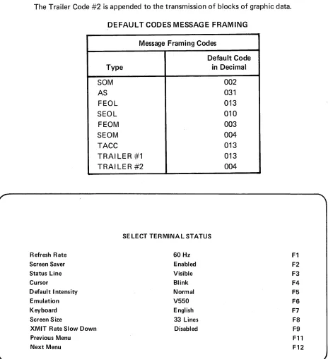
SELECT TERMINAL STATUS
Refresh Rate 60 Hz Fl
Screen Saver Enabled F2
Status Line Visible F3
Cursor Blink F4
Default Intensity Normal F5
Emulation V550 F6
Keyboard English F7
Screen Size 33 Lines F8
XMIT Rate Slow Down Disabled F9
Previous Menu Fll
Next Menu F12
VISUAL TECHNOLOGY INCORPORATED, 540 MAIN STREET, TEWKSBURY, MA 01876
3.9.7 Terminal Status (Menu #7)
Select terminal status is shown in Figure 3-9. Depressing key
~
causes the terminalto advance to the next menu presentation. Depressing key
~
causes the terminalto step back to the previous menu presentation.
3.9.7.1 Refresh Rate (F1)
Depressing key
B
alternately selects 50 Hz or 60 Hz. The refresh rate must matchthe frequency of the terminal's power supply.
3.9.7.2 Screen Saver (F2)
Depressing key
8
alternately enables or disables the screen saver feature, the screensaver feature automatically dims the screen if no character or keyboard interrupt occurs within eight minutes.
3.9.7.3 Status Line (F3)
Depressing key
B
alternately selects visible and blanked. When blanked is selected,the 34th line is not visible to the operator.
3.9.7.4 Cursor (F4)
Depressing key
8
alternately selects the cu rsor between bl ink or steady display.3.9.7.5 Default Intensity (F5)
Depressing key
6
alternately selects the default intensity between normal videoor bold video characters.
3.9.7.6 Emulation (F6)
Depressing key
[3
selects one of three different emulations in alphanumeric mode.V550 mode (ANSI 3.64), VT100 mode, VT52 mode
3.9.7.7 Keyboard (F7)
Depressing key
B
alternately defines the keyboard layout. Subsequent depressionsof key (F5) causes the V550 to step through, the available foreign language layouts as shown in Appendix III.
VISUAL TECHNOLOGY INCORPORATED, 540 MAIN STREET, TEWKSBURY, MA 01876
The select character set command is used to define the character set and requires the optional foreign character set ROM to be installed. Please refer to Section 5.
3.9.7.8 Screen Size (F8)
Depressing key alternately selects the active screen size to 33 lines or 24 lines
in alphanumeric mode.
3.9.7.9 XMIT Rate Slow Down (F9)
Depressing key alternately enables or disables the internal baud rate of host
requested block mode transmissions to transmit at 60 characters per second (600 baud) or the baud rate the terminal is selected for.
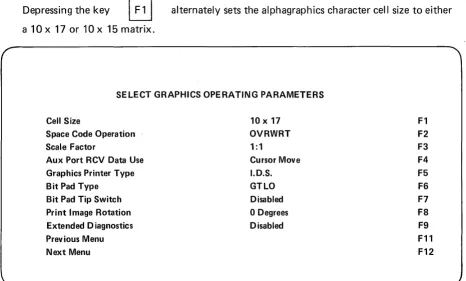
3.9.8 Select Graphics Operating Parameters (Menu
#
8)The select graphics operating parameters screen presentation is shown in F igu re 3-10.
Depressing key
IF
121
causes the terminal to advance to the next menu presentation,in this case menu #1. Depressing key
previous menu presentation.
causes the terminal to step back to the
3.9.8.1 Alpha Character Cell Size (F 1)
Depressing the key
B
alternately sets the alphagraphics character cell size to eithera 10 x 17 or 10 x 15 matrix.
SELECT GRAPHICS OPERATING PARAMETERS
Cell Size
Space Code Operation Scale Factor
Aux Port RCV Data Use Graphics Printer Type Bit Pad Type
Bit Pad Tip Switch Print Image Rotation Extended Diagnostics Prev ious Menu Next Menu
10 x 17 OVRWRT 1:1
Cursor Move I.D.S. GTLO Disabled
o
Degrees DisabledFigure 3-10.
F1 F2
F3
VISUAL TECHNOLOGY INCORPORATED, 540 MAIN STREET, TEWKSBURY, MA 01876
3.9.8.2 Space Code Operation (F2)
Depressing the key'
EJ
alternately defines the operation of space code (hex 20) to beeither "overwriting" or "nondestructive".
Overwriting - a received space code moves the alphagraphics cursor one character position to the right and replaces the previous character with a space.
Nondestructive - a received space code moves the alphagraphics cursor one character position to the right. The previous character remains unchanged.
3.9.8.3 Scale Factor (F3)
Depressing the key
Section 6.3.
alternately sets the scale factor to be 1: 1 or 3:4. See
3.9.8.4 Aux Port Rcv. Data Use (F4)
The depression of key selects one of three aux port modes.
1. Cu rsor Move - A local move of the cross hair cu rsor from the bit pad. Coor-dinates are sent to host upon the depression of a key or pen tip.
2. Pass B.P. to Host - Allows full bi-directional communication through the terminal to the host with the screen reflecting the cross haircursor moves. 3. Pass to Host Transp. - Allows full Bi-directional communication through the
terminal to the host without the cross hair movement on the screen.
3.9.8.5 Graphics Printer Type (F5)
The depression of key causes the V550 to step through the available printer
models. See Section 9.7 for print details.
3.9.8.6 Bit Pad Type (F6)
The depression of key causes the V550 to step through the available bit pad
models. See Section 9.6 for bit pad details.
3.9.8.7 Bit Pad Tip Switch (F7)
VISUAL TECHNOLOGY INCORPORATED, 540 MAIN STREET, TEWKSBURY, MA 01876
NOTE
I f disabled, any key may be depressed to send the cross hair coordinates to the host.
I f enabled, the
I
ENTERI
key or the pen tip must be depressed to send the coordinates to the host.3.9.8.8 Print I mage Rotation (F8)
The depression of key alternately selects 0 degrees of 90 degrees print image
rotation.
A selected print image rotation of 90 degrees causes the graphics display to be rotated 90 degrees from vertical upon transmission to the printer.
3.9.8.9 Extended Diagnostics (F9)
The depression of key
diagnostic tests.
alternately enables and disables the extended power up
WARNING
The extended diagnostics require approximately five minutes to complete.
3.10 HOW TO ENTER FUNCTION KEY SET-UP MODE
The function key set-up mode allows the user to program the function keys from the keyboard and is entered by simultaneously depressing the function and set-up keys on the keyboard.
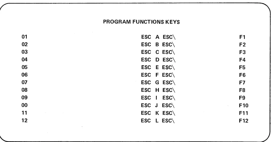
When the function key set-up mode is entered in VISUAL 550 will display the program fu nction keys screen presentation Figure 3-11.
Function key set-up mode is edited by simultaneously depressing the SET-UP and
VISUAL TECHNOLOGY INCORPORATED, 540 MAIN STREET, TEWKSBURY, MA 01876
PROGRAM FUNCTIONS KEYS
01 ESC A ESC\ F1
02 ESC B ESC\ F2
03 ESC C ESC\ F3
04 ESC D ESC\ F4
05 ESC E ESC\ F5
06 ESC F ESC\ F6
07 ESC G ESC\ F7
08 ESC H ESC\ F8
09 ESC I ESC\ F9
00 ESC J ESC\ F10
11 ESC K ESC\ F11
12 ESC L ESC\ F12
Figure 3-11. Program Function Keys Screen Presentation
NOTE
Entering function key set-up mode clears all screen data
3.10.1 Function Key Definition
The user programmable function keys (F 1 - F 12) may contain up to 32 characters each.
Each function key may be independently linked to another function key.
A link uses two (2) character positions.
A function key definit'ion may not start with a link.
Function keys may be loaded from keyboard or remotely via command.
Function key data may be routed directly to the screen or data line.
Function key transmissions are framed as described in Section 7.2.2.
Control functions may be entered and are displayed as defined by control representation mode. See Appendix A V.
Function key data may be stored in non-volatile RAM by executing a save command.
3.11 HOW TO PROGRAM FUNCTION KEYS (F1 THRU F12)
Enter fu nction key set-up mode (Sec. 3.7)
3.11.1 Function .. Keys
VISUAL TECHNOLOGY INCORPORATED, 540 MAIN STREET, TEWKSBURY, MA 01876
the message on the keyboard. The function key string is terminated by depressing the selected function key on the keyboard.
3.11.2 Function Key Programmable Links
A function key link is programmed by simu Itaneously depressing key function and the function key (F 1 - F 12). The selected function key (link) is displayed in high intensity.
3.11.3 Local Transm it of the Function Key
To send the programmed message to the screen (local transm it) instead of the host com-puter is done by depressing the FUNCTION FAST MOV key simultaneously (like a shift key) as the function key data is being entered. Proper loading of a local transmit is signi-fied on the screen by the data being displayed underlined as the key is being programmed.
PROGRAM FUNCTION KEYS
01 CR F1
0,2 LF F2
03 R I N G BL F3
04 F4
12 F12
Example Screen Presentation
Example:
Key Action Comment
FUNCTION SET-UP Enter Function Key Simultaneously
Set-Up Mode
F1 Selects Function Moves cursor to
Key F1 Selected Line 01
CTRL L 1 st Character Displays Ff
Definition
F1 Completes F 1
VISUAL TECHNOLOGY INCORPORATED, 540 MAIN STREET, TEWKSBURY, MA 01876
F2
CTRL E
FUNCTION F3
F3
FUNCTION AND THE CHARACTERS R,I,N,G
CTRL G
F3
SET-UP
Selects Function Key F2
1 st Character Definition
Defines ~ink to F3 and Completes F2 String
Selects Function Key F3
1st, 2nd, 3rd, 4th Character Defin it ions
5th Character Definition Completes F3 Character String Exit Program Key Set-Up Mode
NOTE
Moves cursor to selected Line 02
Displays Eq
Displays 03 in high intensity
Moves cursor To selected Line 03
Function mod ifies (1 ) each character. Underline is displayed
Displays BL
Returns to Menu Set-Up Mode
(1) Each character so modified is directly routed to the screen and is not transmitted. To program the function key