Diagnostics
Z-200 PC Series
.,7J'NI'N
I
data
systems
...
_._--
'--
Contents
Chapter 1 Introduction
Goals 1.1
Hardware Requirements 1.2
Features 1.3
ROM-Based Diagnostic Features
q
Disk-Based Diagnostic Features 1.3
Error Messages , 1.5
Visual Checks 1.5
Diagnostic Approach . . . .. 1.7
Chapter 2 ROM-Based Diagnostics
Power-Up Checks 2.1
Error Messages 2.2
User-Selected Tests 2.5
Chapter 3
f '
Fast TestDisk-Based Diagnostics
3.2
Diagnostic Test Menu 3.4
Diagnostic Test Displays 3.6
Diagnostic Section Menu 3.6
Running Display 3.7
Pause/Continue Test 3.8
Aborting a Test 3.8
Test Complete Indications 3.8
Error Indications 3.9
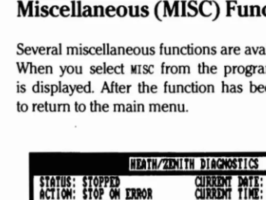
Miscellaneous (MISC) Functions 3.10
Action at an Error 3.11
FINISH 3.12
Date and Time Functions 3.13
Configuration 3.13
CONFIGUR TEST 3.14
AddlDelete Test 3.14
Changing the Testing Sequence 3.14
CONFIGUR MONITOR 3.14
( 0 Test Configuration 3.16
Saving the Configuration " 3.17
Page iv
Contents
Chapter 4 Individual Tests
CPU Diagnostic 4.1
Configuration 4.1
RAM Diagnostic 4.2
Input/Output Port Diagnostics 4.3
C6rifiguration '4.3
CGA Video Diagnostic 4.3
Configuration 4.4
EGA Video Diagnostic 4.4
Configuration 4.4
ZDS Video Diagnostic 4.5
Configuration 4.5
Z-329 Video Diagnostic... . 4.6
Keyboard Diagnostic 4.6
Floppy Diagnostic 4.6
CO~:~e~~
'T~:;
:::::::::::::::::::: ::::::::::::::::::
>: ::: :::::::
:::~
Winchester Diagnostic 4.12
Configuration '.. 4.12
Error Code 4.14
Error Display :. 4:15
Z-304 Diagnostic 4.16
Configuration ·: 4.16
SummaSketch Graphics Tablet Diagnostic : 4.16
Configuration 4.17
Tape Backup System Diagnostic 4.17
Configuration 4.18
IIIII(----~_
...._. '--"' ....
Page V
Contents
Figures
~ 3.1 Diagnostic Monitor Herald . . . .. 3.1 3.2 FasVNormal Test Menu.. . . .. 3.2 3.3 Fast Test Display... . . . .. 3.3 3.4 Diagnostic Test Menu 3.4 3.5 Diagnostic Section Menu 3.6 3.6 Diagnostic Running Display 3.7 3.7 Test Completion Display... 3.8 3.8 Error Indication Display 3.9 3.9 Miscellaneous Function Menu Display 3.10 3.10 Error Action Menu 3.11
3.11 Finish Criteria Menu 3.12
3.12 . Configuration Display... 3.13 3.13 Diagnostic Monitor Configuration Display . . . .. 3.14 3.14 Configuration Exit Display 3.17
Tables
2.1 Possible Power-Up Diagnostic Messages and
Explanations 2.2
Chapter 1
Introduction
Diagnostics for the 2-200 PC Series Computers are provided in two forms: ROM-based and disk-based.
These tests are designed to work with a minimum of operator interface and special test hardware. Ease of operation, consistency of screen mes sages, and clarity of information are the primary goals of this program. Information obtained from the tests can reduce service costs appreciably and minimize hardware downtime.
f '
Goals
Malfunctions can happen with any type of equipment. The goal of these tests is to provide the user with the ability to detect and isolate the cause of faulty machine operation.
The tests outlined here are designed to resolve 90% of detected faults to one subassembly and another 5% of all faults to a maximum of two subassemblies. Whenever possible, faults are resolved to the most likely Large-Scale Integration (LSI) and supporting Integrated Circuits (lCs). Ran dom Access Memory (RAM) and Read-Only Memory (ROM) errors are always resolved to the IC level by disk-based diagnostics. Another goal is to make maximum use of existing hardware to minimize requirements for special test hardware.
Some tests, such as Input/Output (VO) port diagnostics require special test plugs for complete testing.
Page 1.2
Introduction
Hardware Requirements
NOTE: Before performing any test using newly installed diagnostic disks, or when hardware changes have occurred, the diagnostic monitor and several of the diagnostic tests need to be configured for the system being tested. Failure to do so may result in incomplete testing or inaccurate failure messages. Refer to the Configuration section in Chapter 3 for infor mation on how to configure the diagnostic monitor and diagnostic tests.
Hardware requirements for both the ROM-based and disk-based diagnos tics consist of the minimum hardware requirements for a 2-200 PC Series Computer. The disk-based diagnostics can be configured to test most addi tional hardware available for the system. Minimum hardware consists of the following:
• Power supply
• 80286 Central Processing Unit (CPU)
• 256K of system memory (RAM)
• Video controller and display
• Floppy disk controller and at least one disk drive
• Keyboard
The disk-based diagnostics will operate on any 2-200 PC series machine without hardware modification. The tests must be configured properly for the machine being tested.
Although not necessary for test operation, the Microsoft serial mouse is supported and may be used for input to the diagnostic monitor and many of the tests. The diagnostic tests contain a mouse driver and do not require any additional programs for mouse operation. If a mouse is used, it must be configured for the desired port.
Many of the screens displayed by the diagnostic tests contain graphics infonnation. To print these screens, a printer capable of graphics operation
must be used and the appropriate print s<;reen (PSC) utility program from
~,
MS-DOS must be 10aded.. 1f this equipment is not available, only the text information will be printed.
.
--
._
..Page 1.3
Introduction
Features
The features of the ROM-based and disk-based diagnostics may vary from
system to system, depending upon the hardware configuration.
ROM-Based Diagnostic Features
Power indication -
Power indication lamps on the backplane indicate
the presence or absence of correct power delivered from the power supply.
Diagnostic LEOs -
LEOs positioned on the
va
card indicate success
or failure of the ROM-based tests. This feature keeps the diagnostic core
to a minimum and allows resolution of basic system faults without the
need for a functioning display and/or keyboard.
Two levels of ROM-based tests -
ROM-based tests are done at powerup
and also through menu selection. Since time is not a critical factor when
r
accessing the tests in the menu, these diagnostics provide a high degree
of confidence in system integrity.
Coverage -
ROM-based tests are available to test all circuits necessary
to read and execute programs from the mass stQrage device. This results
in considerable reduction of the time required to detect and correct faults
that may occur in the basic system.
Disk-Based Diagnostic Features
Automatic tests -
All portions of the machine that can
beaccessed
without operator input are tested with a single keystroke.
Audible and
visualerror indicators - Errors are indicated by an audible
alarm and distinct display easily recognizable and consistent for all tests.
Page 1.4
Introduction
On-screen fault infonnation - The screen displays infonnation required to correct detected errors. Information included in the display are the function that failed, the most likely hardware causing the problem, and
~\
when the fault occurred.
Consistent test infonnation - Because of the diagnostic monitor ap proach, test modes, error counters, and other features are available for all tests. These features and their screen displays are consistent from test to test.
Retention of configuration infonnation - Mass storage media stores system configuration infonnation with the diagnostic tests. The system con figuration is entered only once for any given computer system.
Test repetition - Tests may be run from 1 to 99 times, from 1 to 23 hours, or continuously. This feature makes it convenient to uncover inter mittent faults or run long-tenn evaluation tests on hardware.
Help screens - Help screens may be accessed at most of the menus and fault displays, providing instant infonnation on fonnats and options ,~ that are available. In addition, the bottom three lines of the screen nonnally display option infonnation for the operator.
Error logging - Error and test completion screens may be discarded or logged on the system's printer or the diagnostic disk. This feature makes it easy to retain and transport fault infonnation. All infonnation logged is date-stamped and time-stamped for later reference.
Startup parameter configuration - Test startup may be configured to allow automatic execution using any set of parameters. This allows the user to generate special diagnostic disks to use in quality assurance testing.
Graphic display of infonnation - The diagnostic monitor program pro vides the capability for tests to convey graphic infonnation to the operator. This feature greatly enhances the scope of data that can be represented.
Page 1.5
Introduction
Simplified keyboard and mouse entries - Test selections may be en tered from the keyboard or the Microsoft mouse during monitor operation. When the keyboard is used, all entries to the monitor program are made using the ENTER, END, and arrow keys.
Fast test - A "fast" test that takes ten minutes or less to execute is provided to detect a minimum of 70% of the possible faults in a system.
Error Messages
As you use the disk-based diagnostic programs to perform tests, any failure causes an error message to display on the screen. The message indicates the most likely cause and specific area of the fault. While the identified components may be at fault, bear in mind that the problem may also be in one of the components connected to the suspected one, the socket, or a foil on the circuit card.
Since there are several models of the Z-200 PC Series Computers that these tests may be run on, no illustrations for specific computers are provided in this manual. Refer to your computer's documentation for infor mation on how the components in your system are organized.
Visual Checks
Unless you have a replacement part at hand, perform the following visual checks in the area of the suspected component before you remove the part.
NOTE: If you assembled your computer from a kit, make the following visual checks very carefully. Factory-assembled products are thoroughly
tested prior to shipment so most of the checks will not be necessary.
Check the computer to see that:
• Circuit cards are properly seated in their connectors.
.
. _.._----~---_-
.
Page 1.6
Introduction
• All cables are properly oriented and completely seated into their connectors.
• Integrated circuits are correctly installed in their sockets and bear the correct part number(s).
Be
sure all pins are fully seated intheir respective holes and none are bent under the
Ie.
• Transistors and diodes are properly installed at their correct loca tions.
• Circuit card foil patterns (especially in the area of any suspected component revealed during the test) are not cracked or have any solder "bridges" between solder pads.
• There are no loose bits of solder or other metal particles lodged between component pins or leads which might cause a short circuit.
After you have made these visual checks, repeat the diagnostic test that revealed the component failure. You may have cured the problem simply by moving or cleaning a cable or connector. If the test still results in an error message, follow the instructions displayed on the screen.
CAUTION: Unless you are skilled at soldering and digital repair tech niques, do not attempt to repair a damaged circuit card.
Page 1.7
Introduction
Diagnostic Approach
Diagnostics have been constructed so that all functions of the equipment required for loading and running disk-based tests can be checked using the ROM-based tests. The disk-based tests contain comprehensive routines to check both the system circuits and the interfaces required to operate peripheral devices. The following procedure is suggested for troubleshoot ing a Z-200 PC system.
1. Turn the system on and correct any faults detected by the power-up tests. If the monitor ROM prompt appears or the system starts to autoboot from the disk, proceed to the next step. If nothing happens or an error message is displayed on the Cathode-Ray Tube (CRT), correct the problem before proceeding. Error indications are pro vided on the screen, power supply LEOs on the backplane board, and the troubleshooting LEOs on the I/O card.
2. Load the disk-based diagnostics disk #1. If the diagnostics load cor rectly and the opening display is shown, proceed to the next step.
If the disk will not boot, return to the monitor ROM program by pressing the ESC key or the CfRL, ALT, and INS keys simultane ously. Next, type TEST and press the RETURN key to use the ROM based tests to troubleshoot the problem.
3. If your model number is not shown on the diagnostic monitor herald,
select any of the models and continue to CONFIGURATION at the diagnostic test menu. Configure the hardware in your system and save it on the diagnostics disk for future use.
4. Press the ENTER key to advance from the diagnostic monitor herald display to the fast/normal menu. Next, run the fast test by pressing the ENTER key. If no error message is displayed, proceed to the next step. If an error message is displayed, correct the problem before proceeding.
Page 1.8
Introduction
5. If no problems are detected by the fast test but a fault is still sus pected, select the normal test and run all of the automatic tests.
This will check all portions of the machine that can be accessed /""\ without additional operator interface. If ALL TESTS COMPLETE, NO ERRORS
FOUND is displayed, proceed to the next step. If an error message
is displayed, correct the problem before proceeding.
6. If a problem is still suspected, run all manual tests by selecting each diagnostic individually, and running sections marked with either an M(manual) or C(combination requiring operator input). Additional actions are required to execute these tests, such as inserting blank disks in floppy disk drives or typing keys on the keyboard. Again, all available information on an error is supplied on the screen when the error is detected.
Chapter
2
ROM-Based Diagnostics
The ROM-based diagnostics are resident in the system ROM and run each time the computer is turned on or reset. These routines include a set of detection tests that check all hardware needed to load programs from the floppy disk. No additional operator interface is required. unless an error is detected or a special operation is desired. This test executes in 4.5 seconds or less if no errors are detected.
Power-Up Checks
The following hardware checks are automatically made when the computer is turned on:
• CPU • ROM • User RAM
• Interrupt control and timer circuits • Parity RAM
• Keyboard microprocessor • Disk drive read
• Disk drive seek function • Disk controller
• Disk Direct Memory Access (DMA) overrun • Disk sector
• Disk Cyclic Redundancy Check (CRC) • Disk address mark
Page 2.2
ROM-Based Diagnostics
Error Messages
Table 2.1 describes possible screen error messages that may occur at pow
erup and what you can
checkto correct the problem.
Table 2.1. Possible Power-Up Diagnostic Messages and Explanations
+++ERROR: CPU failure! +++ +++ERROR: RC* checksum failure+ ++
These two messages indicate that the CPU card may be malfunctioning. The checksum message is a result of a mismatch between a predetermined value and a value derived from the contents of system ROM. Tum the machine off, and then on again.
+++ERROR: RAM failure! Address: XXXX: VYYY, Bit: N, Chip: UXXX+ ++ +++ERROR: Parity hardware failure! Address:XXXXX:VYYY, Chip:UXXX+++
These messages indicate that the CPU is unable to read or write to the RAM
or video RAM memory. If the chip number displayed is a 200 number, the failure / \ is on the CPU card. If the chip number is a 400 number, the failure is on the
expansion card. Before replacing a card, check that the card is properly seated in the backplane slot
+++ERROR: Timer interrupt failure! +++
This message indicates that the timing logic on the I/O card may have failed. Make sure that the card is properly seated and set up for the options installed. Also, check that all optional cards are set up correctly.
+++ERROR: Keyboard not responding or not connected! +++
Amessage of this type indicates that the keyboard did not send the code at powerup to indicate proper functioning. The most likely cause is a disconnected keyboard. Check the cable to make sure it is connected.
++ +Divide by zero l +++ +++Overflowl +++ ++ +Wild interrupti ++ +
+++ERROR: Memory pari ty failure! ++ + +++Non-maskable interrupt I +++
Instructions or interrupts were generated by the computer or a peripheral causing this type of error.
Page
2.3
ROM-Based Diagnostics
Table 2.1 (continued). Possible Power-Up Diagnostic Messages and
Explanations
+++ERROR: CMOS Memory Failure' + + +
A memory test of the CMOS memory/clock chip on the I/O card indicates faulty memory within the chip.
+++ERROR: System Control Processor Failure' ++ +
The system control processor on the I/O card is not responding. This will effect the functioning of the keyboard as well as other vital system functions.
+ ++ERROR: Please replace the back-up battery' + + +
The back-up battery used to keep CMOS memory valid when power is not applied to the system should be replaced.
+ ++ERROR: Bad configuration information found in CMOS' + ++
The memory in the CMOS chip does not contain valid infonnation. The system will automatically execute the SETUP command so the user may set up the CMOS correctly.
+++ERROR: Base memory size error' SETUP: XXXK AC'TUAL: XXXK+ + + ++ tERROR: Expansion memory size error' SETUP: XXXJ(K AC'TUAL: XXXJ(K' + + +
The amount of memory specified in the SETUP command does not equal the amount of memory actually found by the system. Faulty or non-existent memory, or invalid SETUP infonnation may be the cause.
+ ++DISK ERROR: Drive not ready' ++ + +t+DISK ERROR: Seek failure't++ +++DISK ERROR: Cannot reset drive' ++ + +++DISK ERROR: Invalid data read' + ++ ++ +DISK ERROR: Data corrected' + + +
These messages usually occur when you are attempting to boot an operating sys tem. The cause is usually an open drive door-or not having a disk properly inserted in the system.
~,._-_._---,
Page 2.4
ROM-Based Diagnostics
Table 2.1 (continued). Possible Power-Up Diagnostic Messages and
Explanations
++ +DISK ERROR: Disk not bootable' ++ +
This error message indicates that the floppy disk is fine but the boot code read from sector 0 is not a valid executable code.
++ +DISK ERROR: Must run SETUP to boot from Winchester' + + +
This error message is for Winchester only and indicates that an attempt was made to boot from a Wincehster drive for which no SETUP information was specified. Run SETUP and specify a Winchester drive type for that drive.
+++DISK ERROR: Bad disk controller' + + + + ++DISK ERROR: DMA overrun' + + +
Errors of this nature usually indicate a malfunction on the disk controller card, but may also be caused by other defective cards in the system. If any nonstandard
cards have been installed, they should be suspected first in an error condition / \ of this nature.
++ +DISK ERROR: Sector not found' + + + +++DISK ERROR: CRC error' ++ +
++ +DISK ERROR: Invalid address mark' + + +
These errors normally indicate that an operating system was not found on the selected drive, or that you have a defective drive. First, try a different disk. If
this error occurs often, it may be necessary to align the drive.
No error message - Occasionally, a malfunction may occur that, by its nature, prevents anything, induding an error message, from being echoed to the monitor screen. Check to make sure that you are allowing enough time (up to thirty seconds for Winchester systems) for any disk I/O problems to "time out".
Page
2.5
ROM-Based Diagnostics
User-Selected Tests
r'
Several optional test routines are also available from the boot ROM pro gram. On systems that do not have autoboot enabled, the monitor ROM prompt will appear when you turn on the system. The prompt can be
accessed from the system programs by pressing the CfRL, ALT, and INS keys simultaneously. The prompt can be accessed from most ROM-based test menus by typing TEST and pressing the RETURN key. The following information will then be displayed.
CHOOSE ONE OF mE FOLUlWING: 1. DISK READ TEST
2. KEYBOARD TEST
3. BASE MEMORY TEST
4. EXPANSION MEMORY TEST 5. POWER-UP TEST 6. EXIT
( ' - ENTER YOUR CHOICE:
Now you can select one of the desired test sequences by number. The main advantage of testing in this fashion is that these sequences will run continuously until you stop them or an error is encountered. These routines are extremely useful if a malfunction is intermittent, time depen dent, or a result of heat buildup. An onscreen count is displayed to keep track of the number of times the particular test has run. The possible error messages are the same as those described under Power-Up Checks.
After a test is selected, a second screen appears with the test name at the top of the screen and the message TYPE <ESC> TO ABORT in the bottom left corner of the screen. The test count is displayed in the center of the screen. To end the test, press the ESC key. The count will stop and the message TYPE <ESC> TO EXIT will appear at the bottom of the screen. Press the ESC key to return to the test menu.
If an error ends the test, an error message appears underneath the test name and the message TYPE <ESC> TO ABORT will appear at the bottom of
the screen.
•
--~.._--_
..._.._
...
Chapter 3
Disk-Based Diagnostics
The disk-based tests are accessed by loading the diagnostic monitor pro gram from floppy disk #1. This is done automatically when the diagnostic disk is booted. Type DlAG and press the RETURN key to start the diagnos tic monitor program from the operating system.
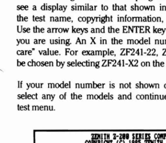
When the diagnostic monitor program is loaded and running, you will see a display similar to that shown in Figure 3.1. This display provides the test name, copyright information, and a menu of model numbers. Use the arrow keys and the ENTER key to select the model of the machine you are using. An X in the model number normally stands for a "don't care" value. For example, ZF241-22, ZF241-32, and ZF241-52 would all be chosen by selecting ZF241-X2 on the menu.
If your model number is not shown on the diagnostic monitor herald, select any of the models and continue to CONFIGURATION at the diagnostic test menu.
ZlJIItH Nil SDIES COIlPUTP PIAQIOSTICS
COPYIIQIT (Cl 1985 ZDlITH MTA SYSTDIS, INC.
7'
11lIJl
1data , - - &y&1:,m&mUlCTED IICIITS LlmID
IIE.JUn~T1I"
~"~\kOS~~
(~(lrE
o)OlJ"~ls
srM~h~iTAITCjII
EWUiu
VIlt8nllARE CLAUl[
INDAI 7-114.
ml
.1l1'COHTIWlCTOnlllfACTURD IS mllTH MIA InTDIS CORPOIWlTlOll or HILLTOP ROAD, IT. JOSEPll. MICHIGAN 49185.USE ADOII AND "DlTD" JlEYS TO SELICT COIlI'IQlMTI 011. "00" JlEY TO EXIT
10_.:111.. ZJ241-Xl 11241-X2
Figure 3.1. Diagnostic Monitor Herald
Page 3.2
Disk-Based Diagnostics
Fast Test
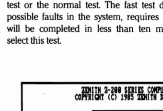
After the model has been selected, the display shown in Figure
3.2
is displayed. At this time, the operator has the choice of entering the fast test or the normal test. The fast test detects a minimum of 70% of the possible faults in the system, requires no additional operator input, andwill be completed in less than ten minutes. Press the ENTER key to select this test.
ZUlITH Z-281 SDIIS COIlPIJTER DIAQtOmCs COPYR GIlT (C)
ass
ZDIITH DATA SYSTDlS, 11tC,"'IIJIlI
I
data~ systems
mTRICTED RIQlTS LEGDtD
~~Et1'IDlJ~~T1I~'
~\.~~~r,(r,(lrE
o r n J l sSf~~~~T:T~I=
COIlPIJTO SOnllAU CLAUSE IH DAR 7-184.9<Al, COIlTMCTORl*lIIrACTURER ISmmH DATA SYSTDIS CORPOMTIOH
or
HILLTOP ROAD, ST, JOSIPll, MICHIGAN .'185, TWO TYPIS OF TISTS AU AUAI~BLE, THE FAST TIST AUTOIlIlTlCALLY CHECKS COtO'IQlm IIADllRI AND RIPORTS Bom LEVIL mULTS IN TDI MIIIITIS OR LISS. THE NOINL TIST CHICKS mUISTED HADIIU AND RIPORTS CHIP LEVEL muLTS, TO START THE FAST TIST JUST TYPE 'ENTO', TO START THE NOINL TIST 1YPI '-)' FOLLOIlD BY 'INTO',FAST TIST: II'~ NO
Figure 3.2. Fast/Nonnal Test Menu
Page 3.3
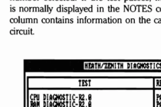
Disk-Based Diagnostics
If the fast test is selected, a display similar to Figure 3.3 is shown. One line of the output is associated with each test required on the model number selected. If the test passes, information on the hardware tested is normally displayed in the NOTES column. If the test fails, the NOTES column contains information on the card most likely to contain the faulty circuit.
Hl'IlYHtmllTH DUCIIOStlCS RlUISIOIl 112,M
mum
MOTESCPU DIAQIOSTIC-RU
RAM DIACHOSTIC-RU
1/0 PORT DIACHOSTlCS-RU
Z4I' UIDEO DIACIlOSTIC-RU
KIYBOAR» DIACHOSTIC-R2,1I
FLOPPY DIACHOSTIC-R1.II WIHCIlESTER DIACHOSTIC-RLII
ALL TESTS COMPLETE
PAsm PASSO PASm PASSO PASSO PASSO PASSED
CPt), TIms,IlfIA,88281 INSTALIJ
MIQ($ TESTO : 8ll - 31
PORT ASERIAL LOCAL LOOP UIDIO RlCIStD YISY
KIYBOAR» RIelSTER TEST
OHI DRIUE
OHI DRIUE
TYPE "00" KEY TO COIlTIItIE
Figure 3.3. Fast Test Display
~."
..
__
._._._._._~_...._ ....-
, ..'~"Page 3.4
Disk-Based Diagnostics
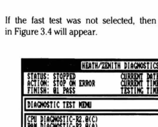
Diagnostic Test Menu
If the fast test was not selected. then a display similar to that shown in Figure 3.4 will appear.
HiATHtmllTH D[ACHOST[CS' RI\I[S[Of! RU8
STATUS: STOPPED CURRDIT DAn: rJ/lM/85
ACTIOf!: STOP Of! ERROR CURRENt T[III:: 15:31:41
FlN[SH: 81 PASS TlSTlNC TIllE: 88:88:88
I
8I
DIACHOST[C TEST IlDII CPU D[ACHOSTIC-R2.8lCI MMDIACHOST[C-R2.8lAI[/0 PORT D[ACHOSTlCS-R2.8lCI
~ U[DEO D[AGHOST[C-R2.8lCI KEYBOARD D[ACHOST[C-R2.8lCI FLOPPY D[ACHOSTIC-RUlCI W[NCHESTER D[ACHOST[C-RUlCI
Figure 3.4. Diagnostic Test Menu
The various areas of the display correspond to the foIlowing:
Top line = Name and revision of current diagnostic monitor program
STATUS: The current state of the test
STOPPED - test is not running RUNNING - test is running PAUSED - test is paused
LOOPING - test is looping on an error
LOADING - test is being loaded from disk
Ac;\'ION: The action to be taken if an error is encountered
STOP ON ERROR - stops the test and waits for operator input
CONTINUE ON ERROR - continues the test after saving error screen on the configured logging device
LOOP ON ERROR - repetitively loops on the failure
•
-.
__
._.~_....Page 3.5
Disk-Based Diagnostics
FINISH: The number of times each test is run n PASSES - where n may be from I to 99
n HOURS - where n may be from I to 23
Com'IMJOUS - continue repeating test until stopped by the operator from the keyboard
ClJIlRENI' DATE: The current system date
ClJIlRENI' TIllE: The current system time
TESTIt«I TIllE: A timer that is set to zero whenever a test is started and stopped when the test is stopped
STARTS: The number of times the test was started
PASSES: The number of times the test passed without error
ERRORS: The number of errors found since starting the test
The items on the bottom line of the screen are available for selection at this time. Use the arrow keys (or the mouse) to get the desired item into reverse videp. then press the ENTER key to begin the function. The various selections result in the following actions:
ALL AIJIWTIC
mrs -
Runs all sections of all tests that are indicated as automatic (A). This is the maximum test of the complete system that can be achieved without individually selecting each test section.SIt«Ili: TEST --Allows selection and expansion of an individual diagnostic test. This function is treated in more detail in a later section.
IIISC - Allows changing the lest action on error, finish parameters, system date, or system time. These parameters are displayed on the top of the screen. Press the END key to get back to the initial diagnostic test menu.
CONFIGJRATION - Allows changing the diagnostic software and hardw:ue con figuration information.
Page 2 of 4
591-4985 CB-3163-40/595-3680
- - _ . _ ~ . _ - - -
..
_.
--
-
..
..---_._---
Page 3.6
Disk-Based Diagnostics
HELP - Displays the diagnostic help menu.
EXIT Returns control to the diagnostic monitor.
r~
Diagnostic Test Displays
Diagnostic Section Menu
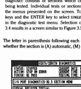
Diagnostic tests contain all the actual test codes used in the system. Each diagnost!c consists of sections which check particular areas of the unit being tested. Individual tests or sections may be accessed by expanding the menus presented on the screen. To expand a menu, use the arrow keys and the ENTER key to select SINGLE TEST, and the desired test shown in the diagnostic test menu. Selection of the I/O DIAGNOSTIC test in Figure 3.4 results in a screen similar to Figure 3.5.
The letter in parenthesis following each diagnostic section name indicates
whether the section is (A) automatic, (M) manual, or (C) miscellaneous. i~
HlAtHtmtlTH IUGIIOStlCS RlUISIOII RU
11/0 PORt DUQtOSTICS-RU $lCTIOH IlDII
SDIU
mama
tESTIULOCAL LOOP BAC)( S[RIAL TESTlA)
OODML LOOP BACK TEST 1M)
PUALW PORt IlitIJUlJpt TESTIIl> PARALW PORt ~u USTIC)
stAtuS; STOPPD QlUDIt ~m: 116/28/85 ACT 1011: stOP 011 ERROR QlUDIt t11ll: 111:46:11
FINISH: 11 PASS tEStllIC TIllE: 11:11:11
~l~II:11111l;r:1IIJlMU'IIl:~1 SIIICLI S[CTIOH 'USC COIII'IQlRATlOH HILP EXIT
Page
3.7
Disk-Based Diagnostics
Selections from this menu are very similar to those in the diagnostic test menu. In this case however, operations are performed on a test section rather than the complete test. Selection of ALL AlJI'OMATIC SECTIONS results in immediate execution of all sections indicated as automatic. Selection of the SINGLE SECTION followed by selection of a section name results in the immediate execution of the section test code. Selection of MISC results in the same functions as at the diagnostic test menu. Selection of CONFIGURATION
results in execution of the configuration code for the currently selected test. Selection of HELP results in an attempt to access the help file for the currently selected test. Selection of EXIT returns control to the diagnostic test menu.
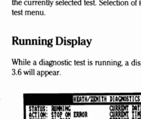
Running Display
While a diagnostic test is running, a display similar to that shown in Figure 3.6 will appear.
HlAtHlmIlTH DUCIIOStlCS RlVISIOH R2.11
StAtUS: 1I111111C QlRRDIt DAtE: 116/28/85 StARTS 1
ACTl"'" StOP"'" DR QlRRDIt till[: .:58:84 PASSES 8
rIMlSii1
81 PASS tEStllIC till!: .:82:53 ERIlORS 811/0 PORT DlAQIOStICS-R2.5 LOCAL LOOP BACX SERIAL tESt
~
PARAIlETIRS UNDER TESTMODI BAUD
RAn • or STOP BITS PARITY LIllCTH CHAR PORT
ASYH 118 1.8 HOIlI 8 B
TYPE "CTRL-BRlAX" KIYS TO PAUSE TEST
Figure 3.6. Diagnostic Running Display
The test and section names are automatically displayed at the beginning of each test. The center ten lines contain information displayed by the test to denote progress or request input from the operator.
Page 3.8
Disk-Based Diagnostics
Pause/Continue Test
While holding the CfRL key down, press the BREAK key to pause
a ./"\
test that is running. The test may not pause immediately. Select the CONTINUE
function on the screen to resume test execution.
Aborting
a Test
Press the CfRL and BREAK keys and select the ABORT function from the menu to abort execution of a test that is running. Control is returned to the menu that was displayed prior to starting the test.
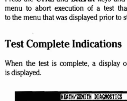
Test Complete Indications
When the test is complete, a display of the format shown in Figure 3.7 is displayed.
HEATHtmlIrH DIAGItOSti CS RIU I$I 011 RU StAtus: STOPPED
ACT 1011: STOP 011 ERROR f1HISH: 81 PASS
11/0 PORt D1AQIOSTlCS-R2.5
aJRRDIt DAtI: 116/28/85 StARtS
aJRRDIt tiM[: 118:54:28 PASSES TEStiltC TIM[: 1lll:16:88 ERRORS
LOCAL LOOP
BAC~
SERIAL TEST1 1 8
:J
ALL TESTS COMPLEtE HO ERRORS rOUND
TYPE '00' K1'Y TO COlltIIllE
Figure 3.7. Test Completion Display
The NO ERRORS FOUND message is displayed only if the error count is zero.
Page 3.9
Disk-Based Diagnostics
The section name is omitted from the display if all the sections of a test were run. If all tests were run, both the test and section names are omitted from the display.
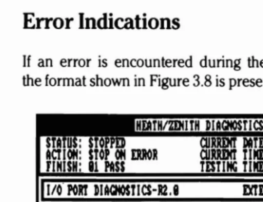
Error Indications
If an error is encountered during the diagnostic operation, a display of the format shown in Figure 3.8 is presented.
FINISH: 11 PASS TESTING TIIII:: 11:11:11
mDllAL LOOP lAC]( TEST STA U: STO
HDTHIZDIITH DIAGHOSTICS lI1'VlSIOIl RUI
aJRRDIT DATI: 119/14185
ACT 1011: STOP 011 ERROR aJRRDIT TlIII:: 15:44:55
1I~:ol:l'I••••a~
SERIAL PORT HaNDSHAXI ERROR alECK TEST PLUG
alECK U315 U318, U3121..U334 011 THE I/O BOARD
WJjCE TH
t
I/O BOAJlIIDTR DRIUER DSR RI : RTS DRIUER CT$ CD
EXPECTED DATA:'1l1I : ACTUAL DATA: IliH : RECEIUING ADDRESS: 83FlH
rtIllI.lllllI TESTSCO IlISC HELP ABORT
Figure 3.8. Error Indication Display
The first line of information under the ERROR Dm:CTED line always indicates the failing function. Beginning with the second line, a list of possible hard ware causes is given. These are in order of most likely to least likely causes of the fault. Any additional lines of information are used to indicate the content of registers or data that may help to resolve the problem.
Page 3.10
Disk-Based Diagnostics
Two lines of data are used to display the contents of processor registers when the fault occurred if REGISTER DISPLAY AT ERROR is selected when configur
ing the monitor options. When this information contained in the registers ~.
is useful for correcting faults, it will be described in the error message. Always save this data for engineering when you need assistance.
Miscellaneous (MISe) Functions
Several miscellaneous functions are available for modifying run conditions. When you select MISC from the program menu, the menu in Figure 3.9
is displayed. After the function has been completed, press the END key to return to the main menu.
STA
us:
OPP ACT 1011: STOP 011 IlIIlORFINISH: 11 I'llSS
I
DIAQIOSTIC TIST IOHlsrARTS I'llSSIS
ERRORS
I
ICPU DIAQlOSTIC ,I(C) RAM DIAQIOSTlC-R2.I(Al
110 PORT DIAQIOSTlCS-R2.lIC)
2489 VIDEO DIACIIOSTIC-R2.I(Cl
KEYBOARD DIAQIOSTlC-R2.I(Cl
FLOPPY DIAQIOSTIC-Rl.I(Cl IlINCIIISTDI DIACIIOSTlC-Rl.I(Cl
ALL AUTOMTIC rISts SINGLE rIST
r:tIll0lll
fiNISH
DATI
TIME
CONFIQlRATIOII HELP EXIT
Figure 3.9. Miscellaneous Function Menu Display
Page 3.11
Disk-Based Diagnostics
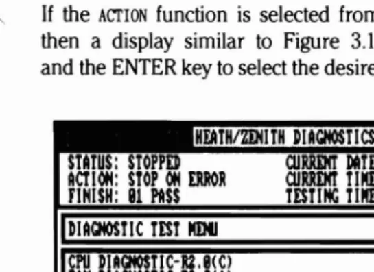
Action at an Error
If the ACTION function is selected from the miscellaneous function menu, then a display similar to Figure 3.10 will appear. Use the arrow keys and the ENTER key to select the desired action if an error is detected.
HEATH/mIlTH DIACItOST ICS RI.V ISION RUlli STATUS: STOPPED
ACTION: STOP ON ERROR FINISH: 81 PASS
CIIW11t DAtE: 89/84185 CIIRRIHt tlllI: 15: 51: 86 TEStlltC tlllI: 118: 118: 118
I
DUGHOStl CtEST IlDtI CPU DIACtIOSTIC-RU(CI MM DIACHOSTIC-R2.8(Al I/O PORT DIAGHOStlCS-R2.8(CI2489 VIDEO DIAGHOSTIC-R2.8(Cl
XIYIlOllRD DIAa«lST!C-RU(Cl FLOPPY DIAGIlOSTIC·R1.9(Cl WINCHESTER DIACNOSTI C-R1.9(Cl
~"(I1.1:.l:lil~:1
COHT IIIII ON ERROR LOOP ON ERROR
ALL AUTOfIAtIC TESTS SIItCLI TEST
!1m
COHFIGUMtlON HELPEm
Figure 3.10. Error Action Menu
~
!
Page 3.12
Disk-Based Diagnostics
FINISH
If the FINISH function is selected from the miscellaneous function menu,
0
then a display similar to Figure 3.11 is displayed. Use the arrow keys and the ENTER key to select the desired test finish criteria. Options include from 1 to 99 passes, from 1 to 23 hours, and continuous repetition. Ifeither PASSES or HOURS is selected, the number for the finish function at the top of the screen will be highlighted; enter the correct value using the arrow and numeric keys, or the mouse.
stATUS: STOPPED ACTIOlt STOP 011 WOR FINISH: 81 PASS
CIIRRDIT DATE: 89/lM185
CIIRRDIT Till[: 15: 52: 15
TESTIItG TI Il[: 88:88: 88
hlACHOSTIC TEST IlEMl
CPU DIACHOSTlC-R2.9IC) RAil DIACIlOSTlC-R2.9IA) 1/0 PORT DIACHOSTlCS-RUIC) Z4U9 UIDEO DIAGNOSTlC-RUIC) J([YBOARD DIACIlOSTI C-RUI C) FLOPPY DIACHOSTIC-RUIC) WINCHESTER DIAGNOSTlC-RUIC)
STARTS PASSES WORS
9 9 9
ALL AUTOIIATIC TESTS SIHGLI TEST
BmI
COHfIQlRATIOIl HELP EXIT...._~--- ~.-
.
HEATHIZDIITH DIACHOSTICS RlV ISIOIl RU8
Figure 3.11. Finish Criteria Menu
Page 3.13
Disk-Based Diagnostics
Date and Time Functions
The date and time functions are used to set the system date and time that appear at the top of the display. It is very important that this is done before running continuous tests so the time recorded for failures is correct.
Select the appropriate function and the value to be set will be highlighted at the top of the screen. You may use either the arrow keys, numeric
keys, or the mouse to set values. While using numeric keys, any non numeric character may be typed to advance to the next field.
Configuration
Selecting CCti'IGURATION at the diagnostic test menu results in a display of the form shown in Figure 3.12.
STARTS B
PASSES
ERRORS
BB
ooma(~I1:.":t. DWTI TIST IlOUt TIST COOl QlR IlOHITOR HELP EXIT
Figure 3.12. Configuration Display
.', - ,~
Page 3.14
Disk-Based Diagnostics
CONFIGUR TEST
Add/Delete Test
To add or delete a test in the monitor configuration, use the arrow keys to select the desired test. If the test was configured, it will be deleted.
If the test was not configured, it will be added. All configured tests have a (C) after the test name. Only configured tests can be accessed from the test menu.
Changing the Testing Sequence
Select MOVE TEST to change the order that tests are run. Next, select the test to be moved and then select the location of the desired test.
CONFIGUR MONITOR
Monitor options can be modified by selecting CONFIGUR MONITOR at the config- . / \ uration menu. This results in the display shown in Figure 3.13.
STATUS: STOPPED ACTIOIj: stOP 0Ij mol
FIHISH: 81 PASS
STARtS 8
PASSES 8
moRS 8
IlOIlltOR OPTIOlIS:
»WY FOR OPERATOR IHPUT: FAST TiST:
ACTIOIj AT moR:
LOOP
FIHISH CRItERIA: COllt IIIIOIIS
TOTAL IIIIIBD
or
PASSiS: tiMES TO IIlH ~ClI SECT I0Ij:LOGGING: »ISK
ASSUMI IQUIPIOM PRI-SITUP: AUTOMAtiC RItURII TO SYSTDl: REGISTER »!SPLAY At moR: COLOR llOIlitOR AUAI LABLE: SERIAL IIOIlSE PORt:
COIjflGUR TEST »ELliE TEST MOUE TiST HELP EXit
Figure 3.13. Diagnostic Monitor Configuration Display
...~..
-
..
..._--_._--_
....
Page 3.15
Disk-Based Diagnostics
The primary purpose of this configuration is to set up special disks for use in manufacturing bum-in and quality assurance testing. If a known configuration is to be tested, the disk can be configured to automatically start, run in a pre-specified manner, and return to the DOS when testing is complete.
Most parameters correspond to functions mentioned earlier. A brief expla nation of the various selections follows:
DELAY FOR OPERATOR INP\1I':
YES - Wait for operator to select model at herald display NO --Run all automatic sections or fast test after starting FAST n:ST (used only if DELAY FOR OPERATOR INPllI' = NO)
YES - Start fast test
. NO - Start running all automatic sections
AcrlON AT ERROR
STOP - Wait for operator input if an error is detected
coo -
Log error and continue test if an error is detected LOOP - Loop on the first error until cancelled by operator FINISH CRITERIA:PASSES - Stop after totaItest has run the specified times
HOURS - Stop after test has run for the specified hours CONTltwUS - Run test until cancelled by operator
TOTAL NUMBER OF PASSES{HOURS Sets initial value for finish criteria if passes or hours have been selected. Value may range from I to 99 for passes and
I to 23 for hours.
TIMES TO RUN EACH SEcrION Number of times each section is run before start ing the next section in tests (normally set to one).
LOC.GING
NONF. - Do not log errors
PRINTER - I))g errors on Ihe system prinkr DISK -lj)g errors in disk file I)IA(i.I<SI.
1))1:( lest starls in file I>IA( j.\.()( i
Page 3 of 4
"aile 3.16
Disk-Based Diagnostics
ASSUME F.QUI P!dENT PP.£St:TUP
YES - Run misc type sections as automatic NO - Run misc type sections as manual
AUTOMATIC ~ TO SYSTF.M:
YF.S - Return to MS-DOS as soon as an error is detected or the finish criteria is met. This is a special option intended to
be used when running the diagnostics in batch mode. It will work only if the delay for operator input option is set to NO and if LOGGING is not set to NONE.
NO - Do not return to MS-DOS until requested by the operator
REGISTER DISPLAY AT F.Rf((}R
YES - Display and log all error information including the value of the CPU registers
NO ---.:.. Do not display the values of the CPU registers and log only the firstl\vo lines of the error message
COLOR MON ITOR AVA ILABLE'
YES - Display diagnostic screens in color NO - Do not use color for diagnostic screens
/~ SER I AL MOUSE PORT
NONE - No mouse is used
COMI - Mouse is connected to the top serial port
COM~- Mouse is connected to the lJollom serial port To exit the monitor options menu press the END key.
Test Configuration
The diagnostic disks Me shipped with pre-prograIlIlTIf~d mnfigurations. listed by llIodel numher and sdecledthrough the l1Ionilor at the beginning of the diagnostics. II cuStOIll mnfigurillions art~needed. most of Ihe diag nostics have a configuration section aVi:lilahle.
By using CONrIWllATlON. lests llIay t~ configured either at the diagnostic test menu. Figure :H, or althe test section ~enu. Figure 3.5. II a configura tion has not been entered prior to running a test, the test allempts to determine what hardwiHl' is IHt'spnt and checks aCClJrdingly. Once a config. uration is enlprl'd, it is mainlained on the disk until deleted hy the operator.
Page 3.17
Disk-Based Diagnostics
Saving
the Configuration
After all configuration information is correct and the display shown in Figure 3.13 is present on the screen, access the EXIT function and the display in Figure 3.14 will be shown.
HbTH/2DHrH DIAGNOSTICS REUISIOM RU STATUS: STOPPED CIJRRINT DtIU: 116/28/85
ACTIOM: STOP OM ERROR CURRINT TIME: 11:48:81
F1HISH: 81 PASS TESTIHC TIME: lIll:lIll:lIll
I
COOl QlRATI OM PROGRAMWRITE COIIJ'IQlRATlOM TO DISK: NO 1m]
MODEL ItAME( I.E. 2II151-21l:
STARTS PASSES
ERRORS
I
8COIIJ'IGlJR TEST DELETE TEST MOVE TEST COIIJ'IGlJR IIONITOR HELP
IEml
Figure 3.14. Configuration Exit Display
If YES is selected, then all information gained in the configuration session is saved on the disk. The next question asks for a file name containing up to eight characters to use for storing the information. In most cases the file name should correspond to the model number for the system.
If no name is typed, the configuration is saved in a special file named DEFAULT.CFG. The configuration must be saved under the default file if a mouse or color option is used.
_---
Page 3.18
Disk-Based Diagnostics
Return To System
The EXIT function at the main menu clears the display screen and returns ~
back to the diagnostic monitor herald. Pressing the END key will return control to the operating system.
~\
Chapter 4
Individual Tests
The following chapter explains all the individual tests found in the disk based diagnostics as well as how to configure each test for proper opera tion.
CPU Diagnostic
The CPU diagnostic checks the timer chip, speaker and their associated
r
circuitry, ROM, interrupt controller, CPU, system crystals, 80287 numeric processor extension, DMA controllers, and the real time clock. Also, it reads the system configuration, ROM version, and displays the results.It also compares the actual system configuration and ROM version against diagnostic configuration if running in the pre-setup mode.
NOTE: The CPU diagnostic assumes the system crystal on the I/O card is 14.314 MHz, the 80286 clock is 12 MHz on the CPU card, and that there are no open or shorted circuits on the printed circuit board.
Configuration
The CPU board diagnostic must be configured properly to ensure all hard ware is tested and error messages result in the correct information. The following may be configured for this test:
( " " TERMINAL TYPE Z241 Z248
Page 4.2
Individual Tests
If ASSUME EQUIPMENT PRESETUP was configured as YES during CONFIGUR MONITOR,
the following information may be changed:
TERMINAL TYPE Z241 Z248
ROM VERSION NUMBER 1.0
NUMBER OF FLOPPY DRIVES
o
1 2NUMBER OF HARD DISK DRIVES
o
1 2DEFAULT DISPLAY TYPE 40 X25 80 X 25 MONO ENHANCED
80287 CO-PROCESSOR INSTALLED NO YES
BASE MEMORY SIZE (IN KILOBYTES) 512 640
EXPANSION MEMORY SIZE OK BYTES
DISPLAY FREQUENCY 60HZ 50HZ
AUTO-BOOT FLOPPY WNCHSTR FLPY/WIN MFM-MONITOR
RAM
Diagnostic
This test requires a Z-200 PC with 512K of RAM located on the CPU/mem ory card. Additional memory resides on optional RAM expansion cards. ~
The first extended RAM card brings the system memory to 640K The remainder of the card and additional cards provide memory in the pro tected memory range above the 1 megabyte boundary. This test does not require configuration or special hardware.
Special sections have been included in the RAM diagnostics to detect faults in the parity generation/detection circuits. The main types of RAM faults tested for and the associated tests are:
• Stuck bits - March II Test
• Address uniqueness - March II Test • Write recovery - March II Test
Page 4.3
Individual Tests
Input/Output Port Diagnostics
The serial and parallel printer ports are located on the I/O card of the 2-200 computer. The I/O card uses jumpers to determine the base ad dresses and interrupt levels of the serial/parallel ports. Only those address combinations are available. The interrupt levels used by the serial and parallel ports are separated. Interrupt levels 4 and 3 are available for the serial port and levels 7 and 5 for the parallel printer port.
The loop back test plugs used for diagnostics are:
• External Loop Back Test - 438-73
• Parallel Port Interrupt Test - 438-64
Parallel port diagnostics check the parallel printer port.
The serial test displays special parameters used to operate the NS16450 ACE, in addition to those parameters displayed by the diagnostic monitor.
Configuration
A configuration is provided to indicate the base address and interrupts used by the I/O card.
PARALLEL/SERIAL PORTIS) TO TEST A B NONE
INTERRUPT FOR THE SERIAL PORT 4 3 NONE
INTERRUPT FOR THE PARALLEL PORT 7 5 NONE
eGA
Video Diagnostic
In the CGA video diagnostic, possible faults are assumed to exist in the display. The diagnostic tests the vide9 controller, the composite or RGB video output, the video I/O circuits, and also provides video patterns for display adjustment.
This test requires a 2-200 PC and at least one color and/or monochrome video display. The video equipment test requires the usual lV alignment tools (i.e., small screwdrivers, etc.).
Page 4.4
Individual
Tests
Configuration
The diagnostic disks are shipped with pre-programmed configurations. .~
The configurations are listed by model number and selected through the diagnostic monitor herald at the beginning of the diagnostics. If cursor configurations are needed, the CGA video diagnostic has a configuration section available for use. The operator needs to know which card the video is located on. An example of the configuration is shown below.
Board the video is located
Z140
I
Z150/Z200I
OTHER10 Z309(Aj/Z409 VIDEO/FLOPPY OTHER
EGA Video Diagnostic
In the enhanced graphics display diagnostic, possible faults are assumed to exist in the display. The diagnostic tests the video controller, the RGB video output, the video I/O circuits, and also provides video patterns for display adjustment.
This test requires a 2-200 PC series computer with a minimum of 128K of RAM and at least one color and/or high-resolution monochrome video display. The video equipment test requires the usual 1V alignment tools (i.e., small screwdrivers, etc.).
A fast test mode is available in diagnostics version 2.0 or higher. The fast test performs abbreviated tests of the automatic sections giving error result to the board level.
Configuration
The following can be configured for the EG,A video diagnostic:
FIRMWARE VERSION OF EGA THAT IS USED
Page 4.5
Individual Tests
ZDS Video Diagnostic
Since the video portion of this diagnostic depends on the integrity of the video RAM, that portion of the RAM diagnostic should be run and any faults detected should be corrected.
This test requires a Z-200 PC with at least 128K of memory, a Z-309A or Z-409 video card, and a Z-419 video card. The video alignment test requires the usual TV alignment tools.
Configuration
Prior to operating the display diagnostics on a new system, or whenever display hardware changes are made, the diagnostic configuration will usu ally need to be updated.
When the ZOS video diagnostic configuration is selected, the following display is shown. The current configuration is indicated by a box around one of the three options to the right of each color. If the diagnostic had previously been configured, the appropriate parameters will be displayed.
VIDEO PLANE OPrIONS
GREEN NONE 32K 64K
RED NONE 32K 64K
BLUE NONE 32K 64K
ARE THE CURRENT SELECTIONS CORRECT? Y N
If the parameters are correct, select Y and the configuration session is ended.
Page 4.6
Individual Tests
Z-329 Video Diagnostic
In the 2-329 diagnostic, possible faults are assumed to exist in the display. The diagnostic tests video alignment, video focus, the Cathode-Ray Tube Controller (CRTC), the video parallel/serial conversion logic, monochrome video output, monochrome display hardware, and the video port I/O cir cuits.
The goals of the diagnostic routines are to identify and isolate all detectable failures in the shortest period of time possible and to provide a means for adjusting the video monitor. Alignment patterns are included for monochrome displays and the complete character set can be displayed upon request.
This test requires a 2-200 PC with at least 512K of memory and a 2-329 monochrome video card. The video alignment test requires the usual TV alignment tools (that is, small screwdrivers, etc.).
Keyboard Diagnostic
The keyboard diagnostic tests the keyboard controller on the I/O board, the interface circuitry, the keyboard processor and the keyboard switch assembly.
Floppy Diagnostic
The floppy disk system in the 2-200 PC can consist of one controller with up to two 5.25-inch drives. This diagnostic test is designed to detect most faults in the drive(s) and controller, and to provide information re quired to repair or adjust them.
Page 4.7
Individual Tests
This test will handle the disk formats listed in Table 4.l.
( '
Table 4.1. Fonnat CoverageTRACKS/ SECTORS/ BYrES/
SIZE SIDES DENSITY TPI SIDE TRACK SECTOR
5.25-inch 1 Double 48 40 80r9 512 5.25-inch 2 Double 48 40 80r9 512 5.25-inch 2 Quad 96 80 15 512
Configuration
Prior to operating the floppy diagnostic on a new system, or whenever disk drive hardware changes are made, the floppy diagnostic configuration will usually need to be updated.
When the floppy diagnostic configuration is selected, the following display will appear. The current configuration is indicated by a box around one of the four options below each drive. If the floppy diagnostic had previously been configured, then the appropriate parameters will be displayed. The cursor will be on the Yat the bottom of the screen.
DRIVE NO. :
o
IA) I IB) DRIVE TYPE 1. 2MB 1. 2MB360MB 360KB
SINGLE SIDED SINGLE SIDED NONE NONE
TO BE TESTED?: YES NO YES NO
ARE ALL PARAMETERS CORRECT? y N
If the selections are correct, choose Y and the configuration session is ended.
If you wish to change a selection, choose N and the cursor will move up to the selection menu.
Pick the appropriate type for each drive, or NOT PRESENT if the drive is not
installed.
Page 4.8
Individual Tests
Once you select a drive type other than NOT PRESENT, YES will be automatically selected for the TO BE TESTED? option. If you do not want this drive to be
tested during automatic testing, then change the selection to NO. If NOT PRESENT / \
is picked for a drive type, then NO will be picked automatically and YES
cannot be picked for that drive.
When the options are correct, type the END key and the cursor will return to the Y at the bottom of the screen.
While the test is running, the following display is shown:
FLOPPY DIAGNOSTIC DRIVE TEST
TEST: WRITE DATA
CURRENT TOTAL
DRIVE: 0 (AJ TRACKS (S) 20 70 ROTATIONAL SPEED: 299 RPM
SIDE: 0 SECTORS(Sj 08 374
ERRORS: RECOVERABLE NONRECOVERABLE
DATA 1
o
SEEK 1
o
WRITE 2
o
READ
o
o
Counters on the screen are cleared whenever the test is aborted or when testing on a new drive begins. If an error is detected, two retries are made in an attempt to recover the data successfully. If one of the retries succeeds, then the appropriate recoverable error counter shows a positive increase. If all three tries fail, the nonrecoverable counter shows a positive increase and the test continues with the next sector.
Any nonrecoverable error, or a total of two recoverable errors of all types in anyone pass (per pass, if the same drive is tested), will result in an error message. If CONTINUE is selected at the error message, the test continues and no additional error messages are displayed. After CON TINUE has been selected, the counters continue to record detected faults,
regardless of the previous number of errors. ~
Page 4.9
Individual
Tests
Errors recorded consist of the following:
DATA: Data read from a sector was incorrect but the "record not found," "lost data," or "CRC error" flags were not set by the controller. This error resulted from returning the wrong sector, incorrect data that was not detected by the CRC and lost data circuits, or data that was corrupted after passing through the disk error detection circuits.
SEEK: The "record not found" flag was returned by the disk controller when attempting to read or write a sector. This error resulted from seeking the wrong track or from an incorrectly formatted disk.
WRITE: The "write protect," "write fault," or "lost data" flags were re turned by the disk controller when it attempted to write a sector. This error resulted from a spike on the write protect sensor, an incorrectly formatted disk, or any malfunction that prevented the processor from loading data quickly enough to ( keep up with the disk controller.
READ: The "lost data" or "CRC error" flags were returned by the con troller when it attempted to read a sector. This error is normally caused by reading incorrect data from the disk. It can, however, result from the processor not reading data quickly enough to keep up with the disk controller.
Alignment Test
Selection of the alignment test results in the following display:
FLOPPY DIAGNOSTIC ALIGNMENT TEST
DRIVE TO TEST: 0 1
Page 4.10
Individual Tests
After the drive has been selected, the following display is presented to request installation of the digital diskette. The model number of the re
quired digital diagnostic diskette will depend on the configured drive type. ~
FLOPPY DIAGNOSTIC ALIGNMENT TEST
INSERT DIGITAL ALIGNMENT DISK INTO DRIVE 0 (Al
THIS TEST REQUIRES A DYSAN MODEL 508-400 REV. B DISK
TYPE ANY KEY TO CONTINUE:
After the test begins, the following display is presented:
FLOPPY DIAGNOSTIC ALIGNMENT TEST
DIGITAL ALIGNMENT TEST - TESTING DISK 0 (Al
MARGINS: SIDE 0 SIDE 1 MINIMUM VALUES
RADIAL ALIGNMENT: 13><12 13><11 08><08 Mil HEAD HYSTERESIS: 13><12 *13><12 08><08 Mil LINEARITY-INSIDE: 12><12 13><11 08><08 Mil OlJI'SIDE: 12><12 13><12 08><08 Mil CLAMPING ACCURACY: 09><09 09><09 08><08 Mil HEAD AZIMlJI'H: 42><42 42><4~ 30><30
--- TYPE SPACE BAR TO LOOP ON MARGIN ----
*** CONSISTENTLY INCORRECT VALUES SHOULD BE VERIFIED USING A *** *** STANDARD ANALOG ALIGNMENT DISK BEFORE DRIVE REPLACEMENT. ***
The digital alignment test depends upon correct seating of the disk in the drive. Parameters often change from pass to pass and several runs of the test should be made to verify results. All tests automatically repeat until stopped by the BREAK key or space bar. An asterisk is placed next to the value currently being computed so that the operator may track the progess of the test. If the space bar is pressed, an individual margin test can be selected and only that margin test will be repeated. Pressing
the space bar again will stop this feature and all tests will again execute. ~
The X> <Y values displayed are arranged as follows:
X- indicates the maximum amount that data can be off track center
line toward the spindle and still be read reliably.
Y- indicates the maximum amount that data can be off track center
line away from the spindle and still be read reliably.
Page 4.11
Individual Tests
To provide readings for Radial Alignment, Head Hysteresis, and Linearity, data is read from a single track which has records written off centerline by progressive amounts. Clamping accuracy is determined by reading tracks where all data is written off centerline by the same amount. For Head Azimuth, data has been recorded on the disk swith a head adjusted at various angles from the perpendicular. X indicates the maximum amount (in minutes) that data can be off in a clockwise direction and still be read; Y indicates the maximum amount, in the counterclockwise direction. The alignment section requires a digital alignment disk and is used, primarily, to determine and display head alignment parameters. Computer parameters include radial alignment, head hysteresis, positioner linearity, clamping eccentricity, and head azimuth.
These parameters are defined as follows:
Radial alignment - The program steps from track 0 (outside of disk) to the middle progressive offset track and determines the last even-num bered sector and the last odd-numbered sector that can be read. The offsets of these sectors is then computed and displayed. Sector pairs are written with offsets of 6-13 milli-inches.
Head hysteresis - The head is moved to the inside track on the disk and then brought back to the middle progressive offset track and the radial alignment is repeated.
Positioner linearity - The alignment test is repeated on the progressive offset tracks that reside on the inside, and on the outside of the disk. Results are displayed for each case.
Clamping eccentricity - The head is positioned over an alternate offset track with an offset of 7 milli-inches (all odd sectors are offset
+
7 milli-in ches; all even sectors are offset-7
milli-inches) and all data on the track is verified. This test is repeated on alternate offset tracks with offsets of 8 and 9 milli-inches. The offsets of the last even-numbered sector and the last odd-numbered sector that can be read are displayed.( ' Head azimuth - The head is positiQned over the azimuth rotation track
(sector pairs written with head azimuth angles of 21, 24, 27, 30, 33, 36, 39, and 42 minutes) and sector pairs are checked for mismatched data. The angles of the last even sector and the ·Iast odd sector that can be read are displayed.
_~---Page 4.12
Individual Tests
Winchester Diagnostic
The disk controller card can have one, two, or three Winchester drives connected to it. The drives are numbered
°
through 2.Each Winchester drive can contain more than one hard disk with a read/ write head for each surface of each disk. By rotating these disks at a relatively high velocity and "flying" the heads very close to the surface of the disk, the capacity and performance of the disk is much improved over floppy disks. Each read/write head is located at the end of a "finger" long enough to reach from the edge of the disk to the center. The other end of each of these fingers is attached to a single swing arm. Therefore, positioning one head over a certain track on one disk surface, positions all the other heads over a related track on all the other surfaces. This set of tracks is referred to as a "cylinder."
The data on each disk surface is formatted into sectors, much as is the data on floppy disks. Sector addressing starts with Cylinder 0, Head 0, Sector 1, and progresses, by sectors through the heads, and then the cylinders.
Since the data transfer portions of this diagnostic depend on the integrity of the RAM, it is assumed that the RAM diagnostic has first been run and that any faults detected have been corrected before executing this diagnostic.
It is also assumed that the system is operational enough to enable the operator to interact with the diagnostic software.
Configuration
Prior to operating the Winchester diagnostic on a new system, or whenever Winchester hardware changes are made, the Winchester diagnostic config
uration should be updated. When the Winchester diagnostic configuration ~
is selected, the following display is shown. The cursor will be on the Y at the bottom of the screen. If the Winchester diagnostic had previously been configured, then the appropriate parameters will be displayed.
Page 4.13
Individual Tests
WINCHESTER CONFIGURATION SUMMARY
DRIVE NO. TYPE 10-15) TO BE TESTED?
0: 2 YES NO
1: NOT PRESENT YES NO
2: NOT PRESENT YES NO
ARE ALL PARAMETERS CORRECT? Y N
If the parameters are correct, pick Yand the configuration session is ended.
If the parameters are not corre