ABSTRACT
SRIVASTAVA, MANOJ
Security Overlay for RMI
(Under the direction of Dr. Gregory T. Byrd)
Distributed object computing refers to allowing objects to be distributed across a network. These objects may be distributed across a number of different computers and across networks.
This thesis presents a popular distributed object architecture, Remote Method Invocation (RMI). As RMI works on a Java framework, it provides the same features Java provides. Its portability, ability to transport objects as a whole, and power to connect to existing as well as legacy systems makes a strong choice amongst other competing technologies. Needless to say, the transport of objects across systems brings along with it the necessity for a strong security framework.
The Secure Sockets Layer (SSL) is a widely popular protocol that currently provides the secure framework RMI needs. Most e-commerce applications these days run over SSL. However, SSL may not the right choice for every application requiring a security backbone. The motivation behind this thesis lies in this thought.
been made to build a new infrastructure using SRP. The infrastructure that has been developed can provide authentication and privacy, as well as maintain message integrity.
SECURITY OVERLAY FOR RMI
by
MANOJ SRIVASTAVA
A thesis submitted to the Graduate Faculty of North Carolina State University
in partial fulfillment of the requirements for the Degree of
Master of Science
COMPUTER NETWORKING Raleigh
2001
APPROVED BY :
Dr. Gregory T. Byrd, Chair of Advisory Committee
Dr. Paul Franzon
BIOGRAPHY
ACKNOWLEDGEMENTS
I consider it a privilege to have been advised by Dr. Gregory T. Byrd on my thesis. His support and patience during my entire tenure under him was exemplary. He was always available for discussions and encouraged innovative ideas.
I would also like to thank T.J. Smith from MCNC, Raleigh for the pointers he would provide every now and then to different implementations. I appreciate the valued inputs Dr. George Rouskas and Dr. Paul Franzon offered during my thesis defense.
TABLE OF CONTENTS
LIST OF TABLES ……….. vi
LIST OF FIGURES ……….. viii
Chapter 1 Introduction ………. 1
1.1 Layout of the Thesis ……… 3
Chapter 2 Remote Method Invocation ……….. 5
2.1 Background ……… 5
2.2 What is Remote Method Invocation ? ………... 6
2.3 Remote Interfaces ………. 8
2.4 Remote Object Registry ………... 9
2.5 Stubs and Skeletons ……….. 10
2.6 Serialization ………. 11
2.7 Dynamic Class Loading ……….. 12
2.8 Callbacks to Applets ….……….. 12
2.9 Distributed Object-Oriented Programming ……….. 13
2.10 Marshaled Objects ……….. 13
2.11 Security for RMI ………. 14
Chapter 3 Secure Sockets Layer ………... 16
3.1 What is SSL ? ………... 17
3.2 SSL Characteristics ……….. 18
3.3 SSL Ciphers ……….… 19
3.4 Cipher Suites with RSA Key Exchange . ………. 20
Chapter 4 Secure Remote Password Protocol …..……….. 25
4.1 Password-based and Public Key based Authentication Mechanisms ………26
4.2 What is SRP? ……….… 27
4.3 Protocol Design ………. 29
4.4 Dictionary Attack ……….. 31
4.5 Summary ………... 32
Chapter 5 Securing RMI ………... 34
5.1 Local Method Invocation ………. 35
5.2 Securing RMI using SSL ……….. 37
5.2.1 Design and Implementation ……….. 37
5.3 Securing RMI using SRP Authentication ………. 61
5.3.1 Design and Implementation ………... 62
5.4 SRP vs. RSA ……….. 64
5.5 Summary ……….. 65
Chapter 6 Applying Secure RMI : Mobile Agents ……….66
6.1 What are mobile agents ? ……….. 66
6.2 Role of Security ……….………68
6.3 Auction System using Mobile Agents ……….. 69
Chapter 7 Conclusion ……… 72
LIST OF TABLES
Table 1 - Mathematical Notation for SRP ……….. 28 Table 2 - SRP Authentication Process ………... 30 Table 3 - Statistical Analysis : Local Method Invocation ………. 35 Table 4 - Performance Table : Running on a single machine …………...39 Table 5 - Statistical Analysis : First Run on a single machine (Plain RMI)……….. 40
Table 6 - Statistical Analysis : Subsequent Runs on a single machine (Plain RMI) ……….. 41 Table 7 - Statistical Analysis : First Run on a single machine
Table 13 : Statistical Analysis : Subsequent Runs across different machines (RMI/SSL) ………. 51 Table 14: Performance Table : Running across two machines over a wide area network ……… 54 Table 15 : Statistical Analysis : First Run across two machines over a wide area network (Plain RMI) ……… 55 Table 16 : Statistical Analysis : Subsequent Runs across two machines over a wide area network (Plain RMI) ………... 55
LIST OF FIGURES
Figure 1 - An RMI Distributed Application ……… 6
Figure 2 - RMI Architectural Diagram …….………. 10
Figure 3 - Protocol Stack …….………. 18
Figure 4 - SSL Handshake ………... 22
Figure 5 : Latency Measurements : Local Method Invocation ……….…… 36
Figure 6 : Latency Measurements : First Run of Plain RMI on same machine ……….……….... 42
Figure 7 : Latency Measurements : Subsequent Runs of Plain RMI on same machine ……….………... 43
Figure 8 : Latency Measurements : First Run of RMI/SSL on same machine ……….………... 45
Figure 9 : Latency Measurements : Subsequent Runs of RMI/SSL on same machine ……….………... 46
Figure 10 : Latency Measurements : First Run of Plain RMI across different machines ……….………. 49
Figure 11 : Latency Measurements : Subsequent Runs of Plain RMI across different machines ……….……….. 50
Figure 12 : Latency Measurements : First Run of RMI/SSL across different machines ……….………. 52
Figure 14 : Latency Measurements : First Run of Plain RMI across two machines over a wide area network ……….. 56 Figure 15 : Latency Measurements : Subsequent Runs of Plain RMI across two machines over a wide area network ………... 57 Figure 16 : Latency Measurements : First Run of RMI/SSL across two machines over a wide area network ……….…. 59 Figure 17 : Latency Measurements : Subsequent Runs of RMI/SSL across two machines over a wide area network ……….. 60
Chapter 1
Introduction
Distributed object computing extends an object-oriented system by allowing objects to be distributed across a heterogeneous network. These objects may be distributed across a number of different computers throughout the network, living within their own address space outside of an application, and yet give the notion of being local to an application.
Three of the most popular distributed object paradigms are Microsoft's
Distributed Component Object Model (DCOM), OMG's Common Object
Request Broker Architecture (CORBA) and JavaSoft's Remote Method Invocation (RMI).
RMI connects to existing and legacy systems unlike some of the other competing technologies. RMI can allow communication with existing servers in non-Java languages. It allows full advantage of Java to be taken when Java needs to be extended to those servers.
RMI thus provides a solid platform for object-oriented distributed computing. One of the significant outcomes of the use of Java and RMI is the need for providing security. During RMI communication, classes are dynamically loaded from remote sources. Safeguards are required to ensure that when the methods of these classes are invoked, they do not violate the integrity of the system.
A number of security protocols are in use to provide security for Java applications. Today, one of the most outstanding protocols in use to secure RMI is the Secure Sockets Layer (SSL). SSL is one of the most widely used protocols for securing web applications. It has been universally accepted on the Internet for authenticated, encrypted communication between clients and servers and ensuring information integrity. SSL supports a number of cryptographic algorithms and allows clients and servers to choose from these algorithms.
Though SSL is a widely used protocol in a number of applications, there may be some areas where it may not be as fast as it should be. The motivation is from the recent emergence of a password-based authentication mechanism called the Secure Remote Password Protocol (SRP). The authentication protocol once successfully completed enables an encryption channel for data flow. The purpose of this thesis is to explore an alternative to securing RMI by the use of this fast authentication mechanism.
provides strong RC4 encryption thus ensuring privacy. Message integrity is also a feature of the secure channel.
As mentioned earlier, there may be some areas where SSL would seem too bulky and complex. One such domain is the area of mobile computing. The second major goal of this thesis is to employ the proposed security overlay in such an environment. With the Internet rapidly evolving, millions of people will have fast access to information through desktops, notebooks, and palmtops from anywhere and everywhere. Mobile code and in particular mobile agents will be an essential tool for allowing such access. These agents, which are pieces of code capable of moving across machines, are meant to be as small and fast as possible. A complex public key based approach to SSL would slow down the communication between machines. It is here where the SRP-based security overlay would fit in.
This report includes an auction application that uses RMI for its communication and has been secured by the SRP-based authentication approach.
1.1 Layout of the Thesis
The purpose of the thesis is to explore an alternative approach to SSL for securing RMI and illustrate the approach by applying it in an application.
Chapter 2 provides background information about RMI and highlights its advantages. It also presents the RMI architecture introducing various terminologies relevant to RMI. It sets the tone for the rest of the thesis by justifying the need for security during RMI communication.
The shortcomings in public key-based authentication with reference to a few applications led to the rise of certain other simpler competing techniques like SRP. Chapter 4 presents this protocol and explains the various aspects of the protocol in detail.
SSL has been the unanimous choice for securing RMI based applications. Chapter 5 talks about the implementation of a RMI based client-server that runs over SSL. A performance analysis has been conducted to analyze the overhead involved in using a security mechanism like SSL. The latter half of the chapter goes on to describe the alternative security overlay that has been developed using SRP authentication. Chapter 5 concludes with a comparative study about SRP and RSA to bring out the advantage of using a password-based authentication approach.
A new approach must be tested or applied in a particular area of relevance to check its performance. Chapter 6 does this by applying the new security infrastructure in a mobile-agent environment.
Chapter 2
Remote Method Invocation
Distributed systems require that processes running in different address spaces, either on the same host or on different hosts, be able to communicate. The Java language supports sockets for communication, which are flexible and sufficient for general communication. The disadvantage with the usage of sockets is that protocols need to be developed at the application layer that allow the client and server to encode and decode messages for exchange. The design of these application-level protocols is cumbersome. Distributed systems turn to other approaches and techniques like Remote Procedure Call
(RPC) and Remote Method Invocation (RMI).
2.1 Remote Procedure Call
client has the illusion of calling a local procedure, when in fact the arguments of the call are packaged and shipped off to the remote target of the call. After the call is received by the server, it calls a routine to service the request and sends a response back to the client.
RPC, however, does not work well with distributed object systems. RPC systems are not focused on any particular language and therefore are essentially least-common-denominator systems. They cannot provide functionality that is available on all possible target platforms. Distributed object systems use another concept called Remote Method Invocation or RMI.
2.2 Remote Method Invocation
According to the Remote Method Invocation Specification[10], Remote Method Invocations (RMI) allow the method of an object in one virtual machine to call the method of an object in another virtual machine (possibly on different hosts) with the same syntax and ease as a local method invocation. Some changes have been made to the core Java programming language to support remote method calls. The changes made include new tools, APIs, and runtime support.
RMI RMI RMI
Figure 1 : An RMI Distributed Application Registry
RMI supports not only the transfer of control between virtual machines but also the passing of objects either by reference or by copy. A program can make a call on a remote object once it obtains a reference to the remote object, either by looking up the remote object in the bootstrap naming service provided by RMI or by receiving the reference as an argument or a return value. Figure 1 shows a simple figure of a client invoking a method on a remote object at the server after obtaining a reference to the remote object.
The primary advantages of RMI are:
• Object Oriented: RMI can pass full objects as arguments and return values, not just predefined data types. In existing RPC systems, the object is decomposed into primitive data types, the data types are converted into streams of bytes and then transmitted. RMI allows entire objects to be directly converted to byte streams and shipped across the wire. This allows full use of object- oriented technology in distributed computing.
• Mobile Behavior: RMI can transport class implementations
from client to server and vice-versa. For example, the code for an object that implements an interface can be fetched by the client from the server.
• Safe and Secure: RMI uses built-in Java security mechanisms that make the downloading of implementations safe. RMI uses the security manager defined to protect systems from potentially hostile downloaded code.
• Easy Construction and Maintenance: It is very simple to write remote Java servers and Java clients that access these servers. This simplicity also makes RMI programs easy to maintain.
• Connects to Existing/Legacy Systems: RMI interacts with
• Portability: All RMI based systems are completely portable to any Java Virtual Machine (JVM).
• Distributed Garbage Collection: RMI uses its distributed
garbage collection feature to collect remote server objects that are no longer referenced by any clients in the network.
• Parallel Computing: RMI is multi-threaded and Java threads may be used to allow concurrent processing of client requests.
RMI supports inter-process communication at a higher level of abstraction. This feature makes RMI a better alternative to sockets for inter-process communication. RMI also supports :
• Dynamic class loading
• Callbacks to applets
• Distributed object model
2.3 Remote Interfaces
According to Edwards[2], In the Java distributed object model, a
remote object is an object whose methods can be invoked from another Java virtual machine, potentially on a different host. In client-server terminology, this object is the server and the object that invokes its methods is the client. The remote object is described by one or more remote interfaces, which are Java interfaces that declare its methods.
In RMI, the remote interface of a server is a Java interface that extends the java.rmi.Remote interface. java.rmi.Remote declares no methods. The
2.4 Remote Object Registry
When a client-server system using RMI is started, the client needs to get its first reference to a remote object. The Remote Object Registry is a mechanism the client can use to get its first remote object reference.
The registry is used to map from string names to remote objects. The registry has both a client and a server interface. A server can bind, unbind, or rebind a name to a remote reference; a client can look up the remote reference for a certain name. The registry stores the stubs (this is discussed later) for the remote objects so that the clients can download them and perform their tasks. The remote object registry listens for requests on a certain port. The default port number for the registry is 1099.
A registry may be started on a particular port by using rmiregistry
which is provided with the Java 2 SDK1. The registry may also be started on a particular port within an application by calling the method
java.rmi.registry.LocateRegistry.createRegistry(port). There are two main classes defined in the JDK to work with registries.
• java.rmi.Naming
• java.rmi.registry.LocateRegistry
The java.rmi.Naming class provides a group of static methods to help bind and look-up objects using a URL-like syntax. Each method takes a URL of the form “rmi://machine:port/name”.
The java.rmi.registry.LocateRegistry class provides a group of static methods for retrieving the registry on a particular host and for creating a registry on the local host. Each application can create only one registry. Also, multiple registries running on the same machine must listen on different ports.
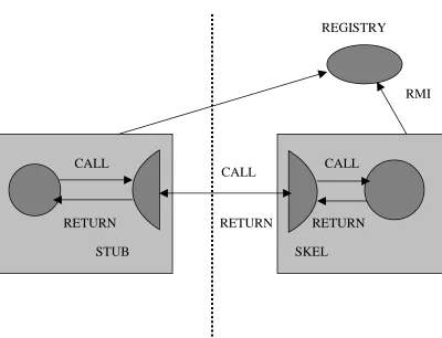
2.5 Stubs and Skeletons
The Java Virtual Machine (JVM) can handle only local method invocations. In order to handle remote method invocations, the server implementing the remote interface has to accept network connections from the clients, read data and convert the method calls to local method calls. On the other hand, the client needs to make an invocation on a local object that represents the remote object. The local object connects to the desired server and sends relevant data. After the invocation, the return data is sent back to the client.
REGISTRY
CLIENT SERVER
Figure 2 : RMI Architectural Diagram
STUB SKEL CALL
CALL
RETURN CALL
RETURN
RMI
At the server side, the server extends a class called
java.rmi.server.UnicastRemoteObject, which takes care of the low-level networking tasks involved in RMI. There is another class, the Skeleton class which is created to call certain methods on a particular server object. This object receives data from the network, invokes methods on the server depending on the methods available and returns the results.
When a client invokes a method on a remote object, it actually invokes a method on a local object called a Stub. The stub is present in the client and manages the network connection for the client. The stub sends a message to the remote JVM, where the skeleton receives it and performs the necessary tasks.
The remote communication is transparent to both the client and the server. The server does not see the skeleton and is under the impression that the client is invoking the method directly. The client thinks that the stub is the remote object itself as the stub implements the same remote interface as the server. The code is written with reference to the remote interface the call is made to.
2.6 Serialization
The mechanism for converting an object into a stream of bytes is known as serialization. The stubs and skeletons use serialization to convert arguments and return values to bytes and reconstitute them. This is achieved by creating objects that implement the java.io.Serializable interface.
2.7 Dynamic Class Loading
Serialization packages up only the member data in an object. Thus, when a serialized object is sent across a network, the receiver cannot use it unless the code is obtained. RMI allows a JVM to dynamically download the implementation of a class as and when needed.
Conventionally, Java applications search for class implementations in its classpath. RMI extends this concept by providing a codebase which is a new location for classfiles. A codebase is provided dynamically to Java applications to allow access to class implementations. It is sent to downloading programs along with the serialization of the object’s data. On receiving the serialized object, if the class is not available locally, it is downloaded from the location indicated in the codebase. The codebase is set by using the java.rmi.server.codebase property. It contains URLs that indicate from where the classes may be downloaded.
2.8 Callbacks to Applets
A callback is used by an object to request notification of a future event. In order to allow callbacks to applets, an applet can create a remote object, export it, and send a reference back to the server. The server can make a remote method call on the reference to send a message to the applet.
2.9 Distributed Object-Oriented Programming
RMI can not only be used to pass standard data types between virtual machines, but also for passing objects. The benefits of RMI are fully realized when it is also used to enable object-oriented solutions for distributed computing problems. The objects can be of the base type or of a more derived type that overrides the methods in the base type. In order to pass the object, the only consideration that must be made is that it must implement the
serializable interface.
2.10 Marshaled Objects
In some applications, it may be necessary that the applications preserve the serialized representation of an object without reconstituting it immediately. The MarshalledObject class provides a way to achieve this by passing the object to it in the constructor. The object is serialized and stored within the MarshalledObject and may be later retrieved using the get()
method on MarshalledObject.
The marshaled objects are Serializable and can be transmitted over the wire in their existing form. When they are reconstituted, they become
MarshalledObjects and not the application-defined class stored within the
2.11 Security for RMI
From the beginning, Java has supported applets, where classes from remote, unknown and possibly untrusted sources are executed locally. There are security implications to being able to download code from other applications.
A majority of the security issues in a distributed system fall into one of the following categories :
• Runtime integrity : Dynamic class loading allows class files to be downloaded from remote sources. Safeguards are required to ensure that when the methods of these classes are invoked, they do not violate the integrity of the system.
Runtime integrity is provided by the classes java.rmi.RMIClassLoader
and java.rmi.RMISecurityManager. The RMIClassLoader loads stubs, skeletons, and the extended classes of parameters and return values. It does bytecode verification on classes loaded from remote sources. Bytecode verification refers to scanning the bytecodes to make sure that they represent a valid Java class.
In Java, application security is provided by the use of a security manager. If one is defined, the system queries the security manager to determine whether the requested operation is currently allowed. RMI provides a simple security manager, called java.rmi.RMISecurityManager. Once this is set, code may be downloaded from a remote source if the permission for this action is granted. The programmer could use this security manager or define his own security manager. In Java 2, security managers are configurable by a
• Authentication : It may be desired that only authorized users have access to a remote object. At the moment, there is no special support built into RMI to enable authentication. If authentication is desired, it needs to be provided on top of RMI.
• Encryption : During remote method invocations, data in the form of parameters and return values may be sent across the network. When the data being transferred is sensitive, such as during bank transactions, data encryption is a must.
RMI does not support encryption by default, but it does have built-in support that allows a programmer to add encryption. RMI uses the socket abstraction for communication. In order to set up an encryption channel, client and server sockets must be defined that implement the desired encryption algorithm. Once this is done, a custom socket factory is created that returns the custom client and server sockets. The drawback to this approach is that all RMI communication, including communication with the RMI registry, is carried out using the custom sockets defined.
Chapter 3
Secure Sockets Layer
As the usage of the Internet proliferates, the need for tools that can guarantee security of electronic transactions over the web has also risen substantially. The Internet uses the Transmission Control Protocol/Internet Protocol (TCP/IP) that allows information to pass through intermediate computers and various networks before reaching its final destination. This kind of transmission opens up numerous ways by which an untrusted third party can hamper secure data transfer.
There are a number of operating platforms and applications that are currently in use and all these need to support secure web transactions. Thus, there is a need for a strong security protocol for browsers and servers that is platform and application independent.
The Secure Sockets Layer (SSL) is one such widely used security protocol that allows secure transmission of data through a public network such as the Internet. SSL has been universally accepted on the Internet for authenticated and encrypted communication between clients and servers. This chapter discusses this protocol and looks at a typical SSL transaction in a detail.
3.1 What is SSL ?
SSL was introduced by Netscape in 1994 with the first version of the Netscape Navigator browser. The ability of Netscape Navigator to encrypt communications was a major selling point for Netscape.
According to Stein[16], SSL is an open, non-proprietary protocol that provides data encryption, server authentication, message integrity, and optional client authentication for a TCP/IP connection.
… …
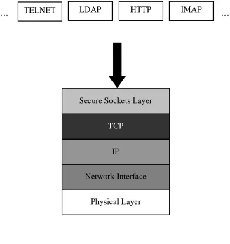
Figure 3 : Protocol Stack
3.2 SSL Characteristics
Some of the main features provided by SSL may be outlined as follows :
• Server authentication: This allows a user to confirm a server's identity. A client may use standard techniques of public-key cryptography to check that a server's certificate is valid and has been issued by a certificate authority (CA) listed in the client's list of trusted CAs. This confirmation might be important if the user, for example, is sending a credit card number over the network and wants to check the server's identity.
Secure Sockets Layer
TCP
Network Interface IP
Physical Layer
• Client authentication: This allows a server to confirm that the user is legitimate. Depending on the kind of authentication being used, the server may either perform a simple password based authentication or may check the client's certificate, if certificates are used. For instance, if a bank needs to give confidential financial information to a customer, it will need to check the client's identity.
• Establishing encrypted communication: In this process, all information sent between the client and the server is encrypted thus providing a high degree of confidentiality. Confidentiality is important for both parties for any private transaction.
The SSL protocol may be divided into two sub-protocols: the SSL record protocol and the SSL handshake protocol. The SSL record protocol defines the format used to transmit data. The SSL handshake protocol involves using the SSL record protocol to exchange a series of messages between the client and server when they first establish an SSL connection. Further communication depends on the outcome of this session. The handshake is designed to facilitate the following actions:
• Authenticate the server to the client.
• Allow the client and server to select the cryptographic algorithms that they both support.
• Authenticate the client to the server.
• Use public-key encryption techniques to generate shared secrets.
• Establish an encrypted SSL connection.
3.3 SSL Ciphers
negotiate which cipher suites to use for mutual authentication and the establishment of session keys.
Some of the popular ciphers used include :
• DES: Data Encryption Standard, an encryption algorithm used by the U.S. Government.
• DSA: Digital Signature Algorithm, part of the digital
authentication standard used by the U.S. Government.
• Diffie-Hellman: The oldest public-key algorithm still in use.
• MD5: Message Digest algorithm which was developed by Rivest.
• RC2 and RC4: Rivest encryption ciphers developed for RSA Data Security.
• RSA: A public-key algorithm for both encryption and
authentication. Developed by Rivest, Shamir and Adleman.
• RSA key exchange: A key-exchange algorithm for SSL based on the RSA algorithm.
• SHA-1: Secure Hash Algorithm, a hash function used by the U.S. Government.
• Triple-DES: DES applied three times.
During the SSL handshake, the client and server identify the strongest enabled cipher suites they have in common and use those for the SSL session. The most commonly used SSL cipher suites use RSA key exchange. In order to serve a large number of users, a broad range of SSL cipher suites may be enabled.
3.4 Cipher Suites with RSA Key Exchange
various ciphers may be combined with message authentication codes to produce cipher suites appropriate for specific applications. The strongest cipher suite using RSA key exchange supported by SSL is Triple DES with SHA-1 message authentication. It supports 168-bit encryption. RC4 is a strong cipher suite and is the fastest among all the supported ciphers. RC4 with MD5 message authentication supports 128-bit encryption. This cipher suite is strong enough for most business or government needs.
3.5 SSL Handshake
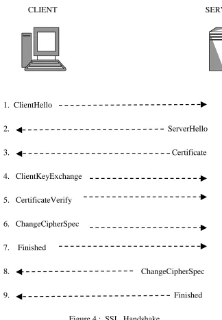
A SSL session always begins with an exchange of messages called the SSL handshake. The handshake as explained in the SSL Specification [11], allows the server to authenticate itself to the client using public-key techniques and then allows the client and the server to cooperate in the creation of symmetric keys used for rapid encryption and decryption of data that is transmitted across the channel. Optionally, the handshake also allows the client to authenticate itself to the server.
The steps involved in the authentication of the two parties and generation of a shared session key are illustrated in Figure 4 and explained as follows :
1. The client starts the SSL communication by sending the ClientHello
message proposing SSL options. The client sends its SSL version number, cipher suites it supports, randomly generated data and other information the server needs to communicate with the client using SSL.
2. The server responds with a message called the ServerHello message. It sends to the client its SSL version number, cipher suites to be used for that session, randomly generated data, session ID and other relevant information.
The client uses the information sent by the server in its certificate to authenticate the server. If the server cannot be authenticated, the user is warned of the problem and informed that an encrypted and authenticated connection cannot be established. If the server can be successfully authenticated, the handshake process continues.
CLIENT SERVER
1. ClientHello
2. ServerHello
3. Certificate
4. ClientKeyExchange 5. CertificateVerify 6. ChangeCipherSpec 7. Finished
8. ChangeCipherSpec
4. Using all data generated in the handshake so far, the client sends a
ClientKeyExchange message. Here the client creates the premaster secret for the session, encrypts it with the server's public key (obtained from the server's certificate) and sends the encrypted premaster secret to the server.
5. If the server has requested client authentication (an optional step in the handshake), the client now sends the CertificateVerify message. The client must authenticate to the server that it knows the correct RSA private key. The premaster secret is thus signed with the client’s RSA private key and sent to the server along with its own certificate. 6. If the server has requested client authentication, the server attempts to
authenticate the client. This is done by trying to verify the signature using the client’s public key found in the client’s certificate. If the client cannot be authenticated, the session is terminated. If the client can be successfully authenticated, the server uses its private key to decrypt the premaster secret, then performs a series of steps (which the client also performs, starting from the same premaster secret) to generate the master secret.
7. Both the client and the server use the master secret to generate the session keys, which are symmetric keys used to encrypt and decrypt information exchanged during the SSL session.
8. The client sends a ChangeCipherSpec message to the server informing it that future messages from the client will be encrypted with the session key. It then sends another message called the Finished
message indicating that the client portion of the handshake is finished. 9. The server sends a ChangeCipherSpec message to the client informing
10. The SSL handshake is now complete, and the SSL session has begun. The client and the server may now use the session keys to encrypt and decrypt the data they send to each other.
According to Thomas [9], in the case of resuming a previous session, SSL reduces the overhead by defining a mechanism where the two parties may reuse previously negotiated SSL parameters. Thus, the client sends a
ClientHello message specifies a session ID from a previous session. The server responds with a ServerHello message agreeing to the session ID. The two parties reactivate the security options using the ChangeCipherSpec
messages and finally send the Finished messages to complete the handshake.
Chapter 4
Secure Remote Password Protocol
A number of password-based authentication mechanisms are in existence today. Password-based authentication has the advantage of being faster and easier to implement. Unlike public-key authentication, long-term keys do not need to be stored or managed. These advantages have encouraged research in developing new password-based authentication protocols.
of an attack is successful when users use simple and easy-to-remember passwords.
The assumption in many existing mechanisms is that the password database on the host is secure from intrusion, else security may be compromised if it is revealed.
It is in such scenarios where the Secure Remote Password Protocol (SRP) is superior to some of the existing password-based authentication mechanisms. This chapter discusses this protocol in detail and looks at the protocol design. First, the implications of password based authentication and public key authentication mechanisms has been discussed.
4.1 Password based and Public Key based Authentication Mechanisms A number of password based authentication mechanisms are based on what the user knows which is generally an identifier and a password. They are generally faster and easier to implement. Unlike public-key authentication, long-term keys do not need to be stored or managed. Passwords carried over a SSL encrypted layer could protect such mechanisms from password sniffing.
Passwords need to be changed over reasonable intervals of time to prevent password guessing. They must be known to either an individual or a group of trusted individuals. They could be stored in an encrypted format to protect against disclosure. Users are aware of this kind of an authentication mechanism as a number of systems in existence today use this concept.
Public key authentication is relatively secure and convenient. The private keys do not need to be transmitted or revealed. Another major advantage of public-key systems is that they can provide a method for digital signatures. It does not involve the sharing of any secret. Each user is solely responsible for protecting his or her private key. Digitally signed messages can be proved authentic to a third party, thus allowing such messages to be legally binding.
A disadvantage of using public key techniques is speed. It is slower than password based techniques. Public key authentication is also generally more difficult to implement.
The two techniques are not meant to replace each other. They have their own merits and are more suitable than the other depending on the application.
4.2 What is SRP?
SRP was first proposed in 1997 at Stanford University as a password-based authentication protocol. Since then it has evolved into an Open Source project and has been deployed as a secure authentication mechanism in companies and organizations worldwide.
The protocol allows users to retain the login and password interfaces while being secure at the same time. The convenience provided is perhaps one of its biggest advantages.
into the encryptions at various stages. This protection is achieved using a Diffie-Hellman style round of computation. SRP is also fast, even when implemented in Java.
SRP does not require any third parties or a PKI infrastructure. It acts like a black box that accepts a password from the user and produces secure authentication and performs key exchange during the process. As a result of the key exchange, security layers may be enabled during the session. Trusted key servers and certificate infrastructures are also not required and the client is not required to store or manage long-term keys.
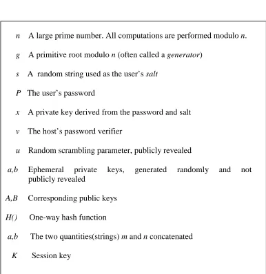
Table 1 : Mathematical Notation for SRP
n A large prime number. All computations are performed modulo n.
g A primitive root modulo n (often called a generator)
s A random string used as the user’s salt P The user’s password
x A private key derived from the password and salt
v The host’s password verifier
u Random scrambling parameter, publicly revealed
a,b Ephemeral private keys, generated randomly and not publicly revealed
A,B Corresponding public keys
H() One-way hash function
a,b The two quantities(strings) m and n concatenated
4.3 Protocol Design
The SRP authentication process consists of two major parts. The first part deals with registering a new user while the second part deals with the authentication of an existing user.
Table 1 indicates the notations used in this section. The notations used are similar to those used by Wu [1].
Let us assume a scenario where a user or client is trying to authenticate itself to a host or server. The values of n and g are agreed upon in advance before the authentication process.
STEP 1: Registering a new user
The client needs to send a verifier (v), which is a mathematically manipulated version of the password. The client picks up a random salt s, and computes the following :
x = H(s, P)
v = gx
The client sends v and s to the server along with its user name. The server on receiving these values, stores them in a password file. The computation of v is implicitly reduced modulo n. The value of x is discarded, as it is a manipulated version of the password P.
STEP 2: Authenticating an existing user
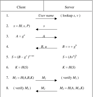
The authentication process is described in Table 2. The steps involved in the process are outlined as below :
2. The server looks up the username in its password file and fetches the matching verifier v and salt s. It sends s to the client. The client computes the private key x using the values of s and the real password
P.
3. The client then generates a random number a, such that 1 < a < n, and computes an ephemeral public key A using g and a. This key is then sent to the server.
Table 2 : SRP Authentication Process
Client Server 1. User name ( lookup s, v ) 2. x = H( s, P) s
3. A = ga A
4. B, u B = v + gb
5. S = (B – gx )a+ux S = (Avu)b
6. K = H(S) K = H(S) 7. M1 = H(A,B,K) M1 ( verify M1 )
4. The server generates its own random number b, 1 < b < n, and computes its ephemeral public key B = v + gb, and sends it to the client along with the randomly generated number u.
5. Using the values available to them, the client and server now compute the common exponential value S = gab + bux. If the client entered the same password that it had used to generate the verifier, only then will the values of S be the same.
6. Both parties hash the value of S into a cryptographically strong session key. The resultant key is K, which is the session key.
7. The two sides now need to prove to each other that they have the same session key. In order to achieve this, the client sends M1, which is
obtained by hashing the values of A, B and K. The server computes M1
itself and checks if the value of M1received matches what it computed.
If the values match, the client is authenticated.
8. The server now sends to the client M2, a hash obtained from A, M1 and K. The client calculates M2 itself and checks if the value received is the
same as what it calculated. If the values are the same, the server is also authenticated and the two parties are ready for data transmission. The two parties may use K to encrypt subsequent session traffic.
4.4 Dictionary Attack
dictionary attack may be carried out by an intruder who masquerades as a legitimate host and convinces the client to make an authentication attempt. However, SRP takes care of the dictionary attack by the inclusion of the verifier in the computation of the host’s ephemeral key B. This may be proved as follows :
Let us assume an intruder, posing as the host, has captured s from a previous session. Also, let us assume that the host computes the ephemeral key B as B = gb in Step 4. The client sends its user name to the host. The host sends to the client the value of s it had snooped earlier. The client then computes A and sends it to the host. The host randomly chooses values for b
and u and computes B and sends it to the client along with u. The client now computes the S as S = Ba+ux and then the session key K. The session key is then sent to the host. The host may notify the client that the password is incorrect.
Now the intruder has obtained A and K from the client. It may guess a password p1, compute x1 and v1 and finally compute S1 as S1 = (Av1u)b.K1 is
constructed from S1. This value is compared with Carol’s value of K. If they
match, the guessed password is correct. As an intruder who does not know v
causes this attack, a solution is to force the host to commit the value of v in Step 4. For this reason, the value of B is obtained by using the verifier also. Modular addition appears to be the simplest operation that does not give out any information about v. Hence, B is defined as B = v + gb.
4.5 Summary
Chapter 5
Securing RMI
Secure Sockets Layer (SSL) is the most widely used protocol for implementing cryptography on the Web. SSL provides authentication, privacy, and data integrity thus ensuring that electronic transactions are safe and secure. There exist standard Java versions of SSL available that allow communication protocols like RMI to be bound by SSL. But in some situations the use of SSL may not be warranted. SSL may be slow due to the use of public-key techniques. Some other techniques could be employed that speed up the SSL protocol. A faster authentication approach for example, may be a good feature of these security layers.
5.1 Local Method Invocation
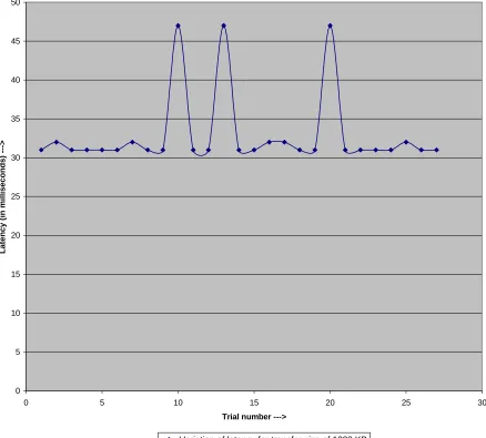
Local method invocation involves the invocation of a method, which resides in the same address space as the calling method. This is the simplest form of method invocation and is faster compared to RMI. In order to understand the overhead RMI by itself causes, Table 3 gives a statistical analysis of the latency involved when a calling method asks the called method to return data of different sizes. The values obtained in this table may be compared with the values obtained in the next section, which analyses in detail the overhead RMI poses. Figure 5 depicts graphically the various latency measurements obtained for local method invocation. The value against the confidence level indicates that there exists a confidence level of 95% that the mean latency is between (15.5+0.2157) milliseconds and (15.5+0.2157) milliseconds, i.e. between 15.7157 milliseconds and 15.2843 milliseconds.
Table 3 : Statistical Analysis Local Method Invocation
Statistical Parameters Transfer Size = 1000 KB
Mean (msec) 15.5
Standard Error (msec) 0.104257
Median (msec) 15.5
Mode (msec) 15
Standard Deviation 0.510754
Sample Variance 0.26087
Kurtosis -2.19048
Skewness 0
Range (msec) 1
For transfer sizes of 1 Kbytes, 10 Kbytes and 100 Kbytes, the latency is extremely small, possibly in the order of microseconds making it difficult to analyze the values. The function defined in JDK 1.3 measures time in the order of milliseconds, due to which the latency for a transfer size of 1000 Kbytes is only presented.
Figure 5 : Latency Measurements Local Method Invocation
0 5 10 15 20 25 30 35 40 45 50
0 5 10 15 20 25 30
Trial number --->
Latency (in milliseconds) --->
5.2 Securing RMI using SSL
The Java Secure Socket Extension (JSSE) 1.0.2 enables secure Internet communications. It provides a framework for Java versions 2.0 and 3.0 of SSL. Using JSSE, developers can provide for the secure passage of data between a client and a server. Client-server based applications using RMI may thus implement an SSL-enabled security layer using JSSE.
By abstracting the complex underlying security algorithms, JSSE simplifies application development by serving as a building block which developers can integrate directly into their applications.
JSSE 1.0.2 supplements the Java 2 SDK, Standard Edition by providing extended networking socket classes. It also provides a socket factory framework for encapsulating socket creation behavior. Thus a user can create a custom socket factory with the desired features and plug it into the framework.
5.2.1 Design and Implementation
In order to secure RMI with SSL, a RMI client-server application needs to be first set up. In this application, once the RMI registry is running, a server is bound to the registry. Then, a client is started and once it looks up the server in the registry, it may invoke remote methods on the server. For the purposes of this thesis, with the intention of measuring latency, the client invokes a remote method that asks the server to return data of different sizes.
TCP. The process of starting a session is the same. When running the client, the truststore to be used must be specified. The truststore contains the list of trusted certificates. As in the previous case, the client invokes a remote method that asks the server to return data of different sizes.
In an SSL-enabled session, as discussed in Chapter 3, the first step is the client-server handshake. Only when the handshake is successful can the data transmission begin. In the example considered here, RSA authentication is carried out with a key size of 1024 bits. Server-side authentication is done using certificates. Once the handshake is complete, a symmetric session key of size 128 bits is established which is used for encrypting further traffic. This is done using RC4 encryption. In this implementation, SSL uses HMAC-SHA1 for message authentication.
A performance comparison has been done between the two systems, the first system being the RMI client-server without SSL and the second RMI client-server system using SSL. The tests done to measure latency were carried out for various data sizes. These measurements were obtained by making ten consecutive remote method invocations on the server. These tests were run on the same machine.
Table 4 : Performance Table Running on a single machine
In the case of RMI using SSL, the latency is much higher. The first run takes approximately 6 seconds. This delay may be further divided into three individual delays. Some amount of time is spent in the assignment of the keystore, keymanager and the truststore, initialization of the truststore and the seeding of the random number generator. This delay amounts to about 5500 milliseconds. The time taken for the seeding itself was about 5000 milliseconds. During this time, the custom socket factory is initialized and a new socket created. The next section, which deals with the handshake, takes approximately 400 milliseconds since this is the first session being created. The last section of time, during which the remote method is invoked and data returned, takes about 50 milliseconds. This delay is greater than the time taken in the case of RMI without SSL since in the former case, the data needs to be encrypted and the message authentication code (MAC) generated.
During subsequent runs, the time taken to invoke the remote method and receive the data is about 50 milliseconds. With reference to the first run,
6672 / 528 234 / 151
1000
5875 / 95 141 / 16
100
5906 / 47 109 / 16
10
5843 / 59 109 / 16
1
RMI/SSL First/Others (msec) Plain RMI
the first two sections do not take place since the assignments have already been done and a cached session has been detected.
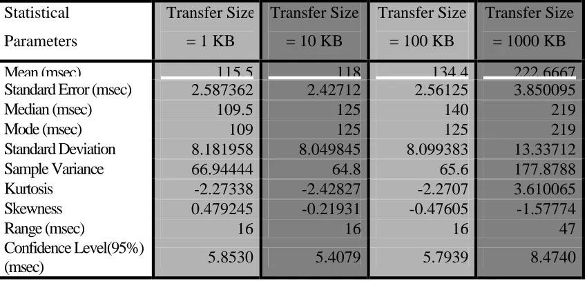
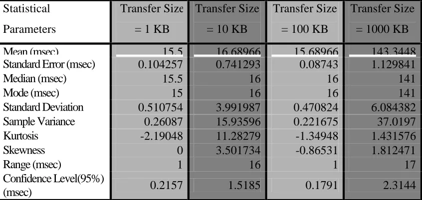
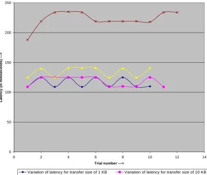
A statistical analysis of the tests has been performed. The values obtained in the tests have been expressed in terms of standard statistical terms such as mean, median, mode and confidence level. Tables 5,6,7 and 8 detail the statistical analysis performed. Figures 6,7,8 and 9 depict graphically the variation of latency for different runs, for both cases, RMI with and without SSL support.
Table 5 : Statistical Analysis First Run on a single machine (Plain RMI)
Statistical Parameters
Transfer Size = 1 KB
Transfer Size = 10 KB
Transfer Size = 100 KB
Transfer Size = 1000 KB
Mean (msec) 115.5 118 134.4 222.6667
Standard Error (msec) 2.587362 2.42712 2.56125 3.850095
Median (msec) 109.5 125 140 219
Mode (msec) 109 125 125 219
Standard Deviation 8.181958 8.049845 8.099383 13.33712
Sample Variance 66.94444 64.8 65.6 177.8788
Kurtosis -2.27338 -2.42827 -2.2707 3.610065
Skewness 0.479245 -0.21931 -0.47605 -1.57774
Range (msec) 16 16 16 47
Confidence Level(95%)
Table 6 : Statistical Analysis
Subsequent Runs on a single machine (Plain RMI)
Statistical Parameters
Transfer Size = 1 KB
Transfer Size = 10 KB
Transfer Size = 100 KB
Transfer Size = 1000 KB
Mean (msec) 15.5 16.68966 15.68966 143.3448
Standard Error (msec) 0.104257 0.741293 0.08743 1.129841
Median (msec) 15.5 16 16 141
Mode (msec) 15 16 16 141
Standard Deviation 0.510754 3.991987 0.470824 6.084382 Sample Variance 0.26087 15.93596 0.221675 37.0197
Kurtosis -2.19048 11.28279 -1.34948 1.431576
Skewness 0 3.501734 -0.86531 1.812471
Range (msec) 1 16 1 17
Confidence Level(95%)
Figure 6 : Latency Measurements First Run of Plain RMI on same machine
0 50 100 150 200 250
0 2 4 6 8 10 12 14
Trial number --->
Latency (in milliseconds) --->
Figure 7 : Latency Measurements
Subsequent runs of Plain RMI on same machine
0 20 40 60 80 100 120 140 160 180
0 5 10 15 20 25 30 35
Trial number --->
Latency (in milliseconds) --->
Table 7 : Statistical Analysis First Run on a single machine (RMI/SSL)
Statistical Parameters
Transfer Size = 1 KB
Transfer Size = 10 KB
Transfer Size = 100 KB
Transfer Size = 1000 KB
Mean (msec) 5720.3 5711.545 5759.3 6349.455
Standard Error (msec) 4.937498 13.37934 9.619483 19.61417
Median (msec) 5719 5703 5765.5 6359
Mode (msec) 5719 5703 5750 6422
Standard Deviation 15.61374 44.37423 30.41947 65.05285 Sample Variance 243.7889 1969.073 925.3444 4231.873
Kurtosis -0.19416 1.486879 -0.06716 -1.53387
Skewness 0.598181 1.091056 -0.64881 -0.04379
Range (msec) 47 156 94 188
Confidence Level(95%)
(msec) 11.1694 29.8110 21.7608 43.7031
Table 8 : Statistical Analysis
Subsequent Runs on a single machine (RMI/SSL)
Statistical Parameters
Transfer Size = 1 KB
Transfer Size = 10 KB
Transfer Size = 100 KB
Transfer Size = 1000 KB
Mean (msec) 41.08333 35.6786 96.4828 513.483
Standard Error (msec) 3.852778 2.87392 5.54441 12.5286
Median (msec) 32 31 79 500
Mode (msec) 31 31 78 484
Standard Deviation 18.87468 15.2073 29.8575 67.4688 Sample Variance 356.2536 231.263 891.473 4552.04
Kurtosis 0.371672 -0.4294 -1.5219 -0.2907
Skewness 1.146983 0.67021 0.33501 -0.1512
Range (msec) 63 48 79 280
Confidence Level(95%)
Figure 8 : Latency Measurements First Run of RMI/SSL on same machine
5600 5700 5800 5900 6000 6100 6200 6300 6400 6500
0 2 4 6 8 10 12
Trial number --->
Latency (in milliseconds) --->
Variation of latency for transfer size of 1 KB Variation of latency for transfer size of 10 KB
Figure 9 : Latency Measurements Subsequent runs of RMI/SSL on same machine
0 100 200 300 400 500 600 700
0 5 10 15 20 25 30 35
Trial Number --->
Latency (in milliseconds) --->
Variation of latency for transfer size of 1 KB Variation of latency for transfer size of 10 KB
Another set of tests was carried out where the client and server were run on different machines but on the same subnet. In order to run a RMI client-server across two machines, the same steps are followed for running a server as in the previous case. The RMI registry is run on the same machine as the server. At the client side, the stub class needs to be made available to the client. For this, the stub class is either copied to the client side or the server source file is compiled and the stub and skeleton class files are generated. Table 9 summarizes the results obtained. As can be observed, the values are in the same range as the values in Table 4. Tables 10, 11, 12 and 13 show the statistical measurements performed for RMI running across two different machines on the same subnet, with and without SSL support. Figures 10-13 indicate the variation of latency for different runs with and without SSL support.
Table 9 : Performance Table
Running across two machines on the same subnet
7234 / 1148 1156 / 1031
1000
5984 / 174 250 / 109
100
5843 / 59 156 / 16
10
6000 / 52 140 / 16
1
RMI/SSL First/Others (msec) Plain RMI
Table 10 : Statistical Analysis
First Run across different machines (Plain RMI)
Statistical Parameters
Transfer Size = 1 KB
Transfer Size = 10 KB
Transfer Size = 100 KB
Transfer Size = 1000 KB
Mean (msec) 139.8 154.1818 246.8 1155.5
Standard Error (msec) 3.392148 3.047557 3.94349 2.536103
Median (msec) 141 154 246 1156
Mode (msec) 156 156 248 1154
Standard Deviation 10.72691 10.1076 12.47041 8.785318 Sample Variance 115.0667 102.1636 155.5111 77.18182
Kurtosis -0.63617 0.688759 -1.54115 1.137613
Skewness 0.263467 0.538619 0.370256 -0.94166
Range (msec) 32 36 32 32
Confidence Level(95%)
(msec) 7.6736 6.7904 8.9208 5.5819
Table 11 : Statistical Analysis
Subsequent Runs across different machines (Plain RMI)
Statistical Parameters
Transfer Size = 1 KB
Transfer Size = 10 KB
Transfer Size = 100 KB
Transfer Size = 1000 KB
Mean (msec) 22.04167 18.7931 112.9655 1031.276
Standard Error (msec) 2.014871 1.372118 1.482644 1.207424
Median (msec) 16 16 110 1031
Mode (msec) 16 16 110 1036
Standard Deviation 9.870814 7.389081 7.984283 6.502178 Sample Variance 97.43297 54.59852 63.74877 42.27833
Kurtosis 0.639921 4.247887 0.120959 -1.22746
Skewness 1.288219 2.229054 1.023578 0.061077
Range (msec) 33 29 30 21
Confidence Level(95%)
Figure 10 : Latency Measurements
First Run of Plain RMI across different machines
0 200 400 600 800 1000 1200 1400
0 2 4 6 8 10 12
Trial number --->
Latency (in milliseconds) --->
Figure 11 : Latency Measurements
Subsequent Runs of Plain RMI across different machines
0 200 400 600 800 1000 1200
0 5 10 15 20 25 30 35
Trial number --->
Latency (in milliseconds) --->
Table 12 : Statistical Analysis
First Run across different machines (RMI/SSL)
Statistical Parameters
Transfer Size = 1 KB
Transfer Size = 10 KB
Transfer Size = 100 KB
Transfer Size = 1000 KB
Mean (msec) 6000.8 5844.545 5979.5 7234.545
Standard Error (msec) 8.910418 6.906339 5.016085 5.434509
Median (msec) 5991.5 5842 5982 7230
Mode (msec) 5976 5856 5982 7230
Standard Deviation 28.17722 22.90574 15.86225 18.02423 Sample Variance 793.9556 524.6727 251.6111 324.8727
Kurtosis -0.46641 -0.55738 -0.10817 0.79014
Skewness 0.919894 0.220755 -0.52544 0.645055
Range (msec) 79 74 53 63
Confidence Level(95%)
(msec) 20.1568 15.3883 11.3472 12.1088
Table 13 : Statistical Analysis
Subsequent Runs across different machines (RMI/SSL)
Statistical Parameters
Transfer Size = 1 KB
Transfer Size = 10 KB
Transfer Size = 100 KB
Transfer Size = 1000 KB
Mean (msec) 49.375 56.34483 178.8276 1149.345
Standard Error (msec) 1.837425 1.831092 3.673252 1.912028
Median (msec) 48 58 178 1148
Mode (msec) 48 63 156 1146
Standard Deviation 9.00151 9.86073 19.78107 10.29659 Sample Variance 81.02717 97.23399 391.2906 106.0197
Kurtosis 0.019687 0.498974 2.939227 1.22491
Skewness -0.28723 -0.72565 1.47958 0.458076
Range (msec) 34 45 81 51
Confidence Level(95%)
Figure 12 : Latency Measurements First Run of RMI/SSL across different machines
0 1000 2000 3000 4000 5000 6000 7000 8000
0 2 4 6 8 10 12
Trial number --->
Latency (in milliseconds) --->
Figure 13 : Latency Measurements
Subsequent Runs of RMI/SSL across different machines
0 200 400 600 800 1000 1200 1400
0 5 10 15 20 25 30 35
Trial number --->
Latency (in milliseconds) --->
Variation of latency for transfer size of 1 KB Variation of latency for transfer size of 10 KB
The third set of experiments conducted using RMI was run over a wide area network. This set of tests helps understand the latencies involved when RMI is used for communication over the Internet and the additional overhead introduced when RMI is secured using SSL. Table 14 shows the results obtained from these tests. Tables 15-18 indicate the statistical results obtained when the runs are performed with and without SSL support. Figures 14,15,16 and 17 depict the variation of latency for different runs with and without SSL support.
Table 14: Performance Table
Running across two machines over a wide area network
9738 / 5463 3635 / 4235
1000
6586 / 2429 555 / 368
100
6335 / 2074 265 / 97
10
6290 / 2110 238 / 60
1
RMI/SSL First/Others (msec) Plain RMI
Table 15 : Statistical Analysis
First Run across two machines over a wide area network (Plain RMI)
Statistical Parameters
Transfer Size = 1 KB
Transfer Size = 10 KB
Transfer Size = 100 KB
Transfer Size = 1000 KB
Mean (msec) 237.7273 265.4 555.3333 3635.071
Standard Error (msec) 7.203649 6.048324 10.84743 50.87806
Median (msec) 230 265.5 551 3535
Mode (msec) 210 270 551 3515
Standard Deviation 23.8918 19.12648 32.54228 190.3683 Sample Variance 570.8182 365.8222 1059 36240.07
Kurtosis -0.74637 -0.19699 -0.52376 0.055655
Skewness 0.638483 0.345639 0.363149 1.359079
Range (msec) 70 61 100 480
Confidence Level(95%)
(msec) 16.0507 13.6823 25.0142 109.9153
Table 16 : Statistical Analysis
Subsequent Runs across two machines over a wide area network (Plain RMI)
Statistical Parameters
Transfer Size = 1 KB
Transfer Size = 10 KB
Transfer Size = 100 KB
Transfer Size = 1000 KB
Mean (msec) 60.41379 96.96552 367.963 4234.8
Standard Error (msec) 4.070958 3.716387 5.417467 4.33282
Median (msec) 50 100 360 4226
Mode (msec) 40 100 350 4226
Standard Deviation 21.92278 20.01336 28.14998 21.6641 Sample Variance 480.6084 400.5345 792.4217 469.3333
Kurtosis -0.24557 -0.66815 0.468038 4.212608
Skewness 0.755215 0.370279 1.112359 2.225337
Range (msec) 80 70 110 80
Confidence Level(95%)
Figure 14 : Latency Measurements
First Run of Plain RMI across two machines over a wide area network
0 500 1000 1500 2000 2500 3000 3500 4000 4500
0 2 4 6 8 10 12 14 16
Trial number --->
Latency (in milliseconds) --->
Figure 15 : Latency Measurements
Subsequent Runs of Plain RMI across two machines over a wide area network
0 500 1000 1500 2000 2500 3000 3500 4000 4500 5000
0 5 10 15 20 25 30 35
Trial number --->
Latency (in milliseconds) --->
Table 17 : Statistical Analysis
First Run across two machines over a wide area network (RMI/SSL)
Statistical Parameters
Transfer Size = 1 KB
Transfer Size = 10 KB
Transfer Size = 100 KB
Transfer Size = 1000 KB
Mean (msec) 6290.1 6334.56 6585.89 9738.4
Standard Error (msec) 53.9968 34.0433 64.1087 50.9305
Median (msec) 6329 6379 6629 9733
Mode (msec) N/A N/A N/A 9834
Standard Deviation 170.753 102.13 192.326 161.056 Sample Variance 29156.5 10430.5 36989.4 25939.2
Kurtosis -0.6124 -1.02 -0.5862 0.05119
Skewness -0.5626 -0.6275 -0.5406 0.55406
Range (msec) 530 280 561 520
Confidence Level(95%)
(msec) 122.1493 78.5041 147.8351 115.2129
Table 18 : Statistical Analysis
Subsequent Runs across two machines over a wide area network (RMI/SSL)
Statistical Parameters
Transfer Size = 1 KB
Transfer Size = 10 KB
Transfer Size = 100 KB
Transfer Size = 1000 KB
Mean (msec) 2110.08 2074.22 2429.32 5462.9
Standard Error (msec) 35.6594 17.3791 37.9105 27.6398
Median (msec) 2073 2063 2364 5418
Mode (msec) 2143 2173 2323 5398
Standard Deviation 174.694 83.347 177.816 126.661 Sample Variance 30518.2 6946.72 31618.6 16043.1
Kurtosis 2.94268 -1.3153 4.07971 1.30835
Skewness 1.54262 0.26888 2.05198 1.1907
Range (msec) 771 270 711 501
Confidence Level(95%)
Figure 16 : Latency Measurements
First Run of RMI/SSL across two machines over a wide area network
0 2000 4000 6000 8000 10000 12000
0 2 4 6 8 10 12
Trial number --->
Latency (in milliseconds) --->
Figure 17 : Latency Measurements
Subsequent Runs of RMI/SSL across two machines over a wide area network
0 1000 2000 3000 4000 5000 6000 7000
0 5 10 15 20 25 30
Trial number --->
Latency (in milliseconds) --->
One of the main outcomes of these experiments is that there is a need to figure out a way to seed the random number generator ahead of time and before the session begins. Since the seeding itself takes about 5 seconds, this delay is a substantial part of the total delay.
5.3 Securing RMI using SRP Authentication
Authentication using SRP has been dealt with in Chapter 4. This section focuses on building a SRP-authenticated RMI client-server. ARCFOUR, an equivalent algorithm to RC4, is used for encryption. Message authentication is provided by HMAC-SHA1. A custom socket factory to provide encryption and message authentication has been built and is plugged in once the authentication is successful. Figure 18 depicts a protocol diagram for SRP authentication.
CLIENT SERVER
1. Send Username
2. Send Salt
3. Send Client Public Key
5. Send M1
6. Send M2
7. Encrypted traffic
Figure 18 : Client-Server Handshake during SRP Authentication
5.3.1 Design and Implementation
In an SRP-authenticated RMI client-server application, the authentication is provided at the application layer. If the authentication is provided in the custom socket factory, then the same socket factory will be used for all communication, including that with the registry. This is not desired. Also, the login name will need to be passed down to the socket factory so that it can be sent across to the server from the client.