SEISMIC RESPONSE EVALUATION OF THE NPP STRUCTURES
AFTER FLOOD EVENT: A CASE STUDY
Yalcin Bulut1, Omer O Erbay2
1 Assistant Professor, Turgut Özal University, Ankara, Turkey
2 Managing Partner, MATRiSeb, LLC, Ankara, Turkey
ABSTRACT
This study investigates the effects of deteriorated soil beneath the nuclear island at a Nuclear Power Plant (NPP) following a flooding event. A case study is considered in order to understand potential effects of the negatively affected soil on the structural integrity and seismic response of the combined Class I structures, namely the Auxiliary Building, Containment Shell and Dome Structure, and Containment Internal Structure. The foundation mat for the combined Class I structures is an integral unit supported on steel pipe piles driven to bedrock. The seismic behavior of the nuclear island due to the presence of deteriorated soil under the foundation mat is evaluated by comparing the seismic response that is calculated by using the altered soil properties to the seismic response determined based on the initial design basis criterion for Class I structures. The maximum absolute floor accelerations due to Maximum Hypothetical Earthquake are calculated using response spectrum analysis. The effect of changes in soil properties on the floor response spectra that are used in seismic design criterion for the equipment and piping is also evaluated.
In the case study, the original design basis soil-structure dynamic model based on the data provided in the
Updated Safety Analysis Report (USAR) is used. The design basis horizontal dynamic model of the NPP structures is reconstituted and validated using a seismic response comparison approach, in which the maximum absolute acceleration response due to Maximum Hypothetical Earthquake and the floor response spectra due to the 1940 El Centro N-S component are compared with the USAR. In the case study, the reconstituted dynamic model is used and modified to predict the dynamic behaviour of the
Auxiliary Building and Containment Structure for 10ft depth of the postulated deteriorated soil. The case
study demonstrates that even under the extreme postulation that all piles beneath the Auxiliary Building and Containment Structure is surrounded by deteriorated soil and up to the 10ft of pile is completely (laterally) unsupported by the soil, the seismic response of the buildings and structures is less than the original design basis seismic response. The design basis criteria and floor response spectra used for equipment and piping qualification remains unaffected.
INTRODUCTION
Evaluation of the Nuclear Power Plant (NPP) structures following a flooding event is crucial for the safety and operability. The flooding event may result in the loss of the plant’s off-site power supply and safety systems and damage structures and equipment throughout the plant. Regulators require a flood risk assessment to be performed and worst-case flooding scenario is taken into consideration in order to plan
adequate procedures to protect the NPP (IAEA Safety Standards Series - SSG-18, 2011).
Containment Structure, this study investigates structural integrity and seismic (dynamic) response of the combined Class I structures.
Part of the motivation behind this paper is to offer a concise approach for evaluation of existing NPP
structures subjected to flooding. The paper is organized as follows: the next section presents the
methodology used in the study and the following two sections review the Class I structures and seismic design basis of the NPP structures investigated in the case study. The last two sections present the reconstitution of the dynamic model and the modified model used in the case study, and the potential effects of the deteriorated soil on the seismic response of the NPP structures. A brief summary of the main points concludes the paper.
METHODOLGY
This study uses the original design basis soil-structure model based on the data provided in the Updated Safety Analysis Report (USAR). The design basis dynamic model of the NPP structures is reconstituted based on the stiffness matrix that is obtained from direct stiffness approach using GT-STRUDL Finite Element Software. The reconstituted GT-STRUDL model is validated using a seismic response comparison approach, in which the maximum absolute acceleration response due to Maximum Hypothetical Earthquake (MHE) and the floor response spectra due to the 1940 El Centro N-S component are compared with the plant design basis reported in the USAR. The seismic behavior of the auxiliary and containment buildings due to postulated deteriorated soil under the foundation mat is evaluated considering a 10ft deep affected soil zone under the entire foundation.
The reconstituted GT-STRUDL model is used and modified by modeling the steel pipe piles under the foundation mat with a single super column element and any contribution to the soil-pile interaction of the deteriorated soil is conservatively ignored. The soil stiffness is entirely ignored over the assumed height of the hypothetical deteriorated soil. The effect of the postulated deteriorated soil is evaluated by comparing the seismic response for the following cases with the initial design basis:
1.The maximum absolute floor accelerations due to MHE obtained from response spectrum analysis.
2. The floor response spectra due to the 1940 El Centro N-S component obtained from time history analysis.
NPP CLASS I STRUCTURES
Class I structures, namely the Auxiliary Building, Containment Shell and Dome Structure, and Containment Internal Structure, considered in this evaluation can be briefly described as follows:
Containment Structure: The Containment structure is a reinforced concrete pressure vessel partially pre-stressed, with cylindrical walls, a domed roof and a bottom mat incorporating a depressed center portion for the reactor.
Auxiliary Building: The Auxiliary Building is a Class I structure, and is located immediately adjacent to the containment structure. The auxiliary building is a multi-floored structure of reinforced concrete construction.
The foundation mat for the auxiliary building and the containment structure is an integral unit supported on steel pipe piles driven to bedrock.
DYNAMIC MODEL OF THE SEISMIC DESIGN
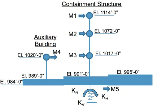
The analytical model for the seismic design of the containment and auxiliary building consists of several lumped masses distributed on equivalent column members (stick model) as depicted in Figure 1. Mass M1 represents the dome with the ring girder; masses M2 and M3 represent the cylindrical shell; mass M4 represents the auxiliary building; and, mass M5 represents the mat and the internal masses of the containment structure. The analytical model of the five masses was assumed to have 13 degrees of freedom, namely; two horizontal translations in the principal directions of each mass, two rotations of the entire assumed rigid system, and uncoupled vertical motion of the entire mass of the system. The five translational movements of the masses and the rotational movement of the entire mass in the same plane are coupled. The uncoupling of the vertical motion and the horizontal/rocking motions in the two vertical planes was based on the fact that the center of gravity of the entire system reasonably coincides with the center of gravity of the elastic foundation.
Figure 1. Dynamic Model of the NPP Structures
The foundation springs used in the dynamic model, are depicted in Figure 1. The lateral stiffness coefficient of the foundation, KH, depends on the soil modulus and elastic properties of the piles and was determined from the field tests of piles and using the approach presented by Broms (1964). Vertical and rotary stiffness coefficients, KV and KƟ respectively, were obtained on the basis of elastic properties of the piles and bedrock. The rocking (KƟ) and vertical (KV) springs are calculated on the conservative assumption that the axial rigidity of the piles alone, without the effect of the surrounding soil, contributes to the stiffness of the springs.
Seismic Load - Maximum Hypothetical Earthquake (MHE)
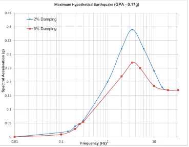
Per USAR, all Class I components, systems and structures of the NPP are designed to the response of a peak ground acceleration of 0.17g acting in the horizontal direction and two-thirds of 0.17g acting in the vertical direction, representing the Maximum Hypothetical Earthquake (MHE). The ground response spectrum curves for 2% and 5% of critical damping for the MHE are presented in Figure 2.
Figure 2 – Horizontal Ground Response Spectra for the NPP Structures
Seismic Design Basis of Equipment and Piping
Per USAR, the seismic design criterion for the equipment is that the lowest dominant natural frequency of the equipment or piping is 6 Hz or above in the horizontal direction, and 18 Hz or above in the vertical direction. Therefore, the ground motion response spectrum, normalized to the acceleration at the elevation of the equipment support, is used as the input for the analysis to determine the equipment response. The basis for this criterion is that the lowest dominant natural frequency of both the containment building and the auxiliary building is approximately 3 Hz in the horizontal direction and 9 Hz in the vertical direction and that higher modes of vibration of the building will not contribute significantly to the response of equipment attached to the building. For the seismic analysis of the equipment, horizontal floor response spectra have been developed using the same dynamic model, but using the computed responses to actual time-history inputs of 1940 El Centro N-S component. The envelope of maximum peaks was used for the construction of the horizontal floor spectra for equipment frequencies approximately between 1 Hz and 6 Hz, and for the vertical floor spectra for equipment frequencies between approximately 5 Hz and 15 Hz. Normalized ground motion response spectra were used for equipment frequencies of about 6 Hz and above for the construction of horizontal floor spectra and for equipment frequencies of about 18 Hz and above for the vertical floor spectra.
! !"!# !"$ !"$# !"% !"%# !"& !"&# !"' !"'#
!"!$ !"$ $ $!
2% Damping
5% Damping
S
pe
ctr
al
A
cc
eler
ati
on
(
g)
Frequency (Hz)
RECONSTITUTION OF THE NPP STRUCTURES DYNAMIC MODEL
In this section a dynamic model is developed using the GT-STRUDL computer program and the member and material properties given in USAR. The representation of the stick model used in GT-STRUDL is depicted in Figure 3.
Figure 3 – GT-STRUDL Stick Model of the NPP Structures with model degree-of-freedoms
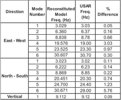
Modal frequencies of the reconstituted dynamic model in GT-STRUDL are calculated and a comparison with the values given in the USAR is presented in Table 1.
Table 1 – Modal Frequency Comparison USAR vs Reconstittued GT-STRUDL Model
Based on the results in Table 1, the GT-STRUDL model is in close agreement with USAR design basis model and can be used for dynamic analysis of the NPP Auxiliary Building and Containment Structure.
Direction Mode
Number
Reconstituted Model Freq. (Hz)
USAR Freq. (Hz)
% Difference
1 3.029 3.03 0.05
2 6.360 6.37 0.16
3 8.838 8.78 0.66
4 19.576 19.00 3.03
5 23.525 23.30 0.97
6 30.607 30.70 0.30
1 3.023 3.02 0.11
2 6.222 6.23 0.14
3 8.869 8.85 0.22
4 20.451 20.30 0.74
5 24.700 24.40 1.23
6 30.671 29.00 5.76
Vertical 1 9.112 9.12 0.09
East - West
MODEL VALIDATION
The reconstituted model is validated using a seismic response comparison approach, in which the maximum floor absolute accelerations and base shear response due to MHE and the floor response spectra due to the 1940 El Centro N-S component are obtained using GT-STRUDL analysis stick model and compared with the USAR. The maximum absolute acceleration response of the reconstituted model due to the USAR Ground Motion Response Spectra is obtained from response spectra analysis. The comparison of the maximum accelerations with the USAR is presented in Table 2.
Floor response acceleration time histories of the reconstituted model due to the 1940 El Centro N-S component are obtained from dynamic time history analysis. The comparison of the floor response spectra from reconstituted model with the MHE floor response spectra contained in USAR is presented in Figure 4.
Figure 4 – MHE Floor Response Spectra at the 5th Mass due to 1940 El Centro N-S component
MODIFIED DYNAMIC MODEL
A case study is performed in order to quantify the seismic behaviour of the auxiliary buildings due to
deteriorated soil under foundation mat. In the case study the reconstituted model is used and modified to
from bedrock to the foundation mat at a lower elevation than the bottom of the 10ft deep deteriorated soil at El. 973.5ft.
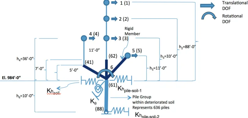
Figure 5 – Modified GT-STRUDL Stick Model of the NPP Structures with degree-of-freedoms (DOF)
(GT-STRUDL model node numbers are depicted in parenthesis.)
The reconstituted dynamic model is modified to use in the deteriorated soil case study. The representation
of the GT-STRUDL model used in the case study is depicted in Figure 5. In Figure 5, Khpile-soil-1 represents the pile group that remains below the bottom of 10ft deep deteriorated soil (length of these piles are around 30-35ft and 167 of the 803 piles are considered to fall in this group). Khpile-soil-2 represents the pile
group that are exposed within the deteriorated soil (length of these piles are around 47-51.5ft and 636 of
the 803 piles are considered to fall in this group).
The following assumptions are made in modifying the reconstituted model in which the foundation pile group surrounded by the deteriorated soil is modelled as a beam element (shear and flexural):
1. It was conservatively assumed that the deteriorated soil spread under the entire Auxiliary
Building and Containment Structure combined foundation mat and the impact on the soil-pile foundation system is analysed. The depth of the postulated deteriorated soil is 10ft.
2. Contribution to the soil-pile interaction of the deteriorated soil is conservatively ignored. That is,
no credit whatsoever is taken for the lateral stiffness of the deteriorated soil, Bowles (1996).
3. The pile group is modelled as a beam element. The pile head is rigidly connected to the
foundation mat and it is rotationally fixed. The bottom end of the pile is considered to be free to
rotate although the pile is continuous with the surrounding soil stratum below the deteriorated soil
and is partially restrained. Moment release is applied at the soil surface and bending stiffness of a single pile is calculated as 3EI/L3, where E is modulus of the elasticity of the pile steel material, I is the moment of inertia of the pile section and L is the pile depth within deteriorated soil.
4. The soil around the embedment walls and the foundation mat remains within deteriorated soil, therefore, the stiffness contribution of the soil-structure stiffness normal and parallel to the embedment walls (Khsoil) is taken as zero.
5. The fundamental engineering properties of the soil below the deteriorated soil depth is not changed, therefore, the soil-pile stiffness (Khpile-soil) below the postulated deteriorated soil remains unchanged. This assumption is consistent with the design basis approach for the piles that is initially presented by Broms (1964).
6. The GT-STRUDL model is updated based on two sets of pile lengths; namely, 167 piles are
contribute to change of the soil-pile stiffness; therefore, their stiffness (Khpile-soil-1) is introduced at the foundation El. 983.5ft. The stiffness of 636 deteriorated soil exposed piles (Khpile-soil-2) is introduced at the bottom of 10ft long beam element.
7. The stiffness of two pile groups, namely Khpile-soil-1 and Khpile-soil-2, are calculated by subtracting the stiffness contribution of the soil-structure stiffness normal and parallel to the embedment walls from the design basis soil spring constants (refer to KH in Figure 1) and by distributing the remaining stiffness proportional to the number of piles of the two pile groups.
8. Rocking stiffness of the foundation (refer to KƟ in Figure 1) is based on the axial stiffness of the
piles and therefore it remains same as in the design basis model. The rocking stiffness is introduced at the foundation elevation (El. 984’-0” in Figure 5).
The modified reconstituted GT-STRUDL model is used for seismic response spectra and time history analysis. The soil-pile interaction stiffness is introduced to model as lumped spring stiffness at the foundation level (El. 984’-0” in Figure 5) and at the bottom of the 10ft long beam element. These springs are both theoretically supported at the bedrock elevation since per USAR the soil-pile interaction spring stiffness constants are calculated based on the in-situ pile tests performed during the site investigation studies of the plant. Therefore for the seismic response analysis the input ground spectra and ground time history accelerations are applied at the model supports where theoretically the piles socketed into bedrock.
Seismic Analysis Using Modified Reconstituted Model
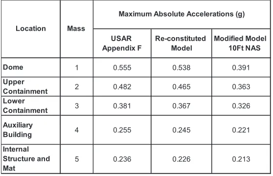
The seismic response of the modified reconstituted model is calculated using GT-STRUDL. The maximum absolute acceleration response due to MHE and the floor response spectra due to the 1940 El Centro N-S component are calculated and compared with the USAR. The maximum absolute acceleration response of the modified reconstituted model due to the USAR MHE ground motion input is obtained from response spectra analysis. The comparison of the maximum accelerations with the USAR accelerations is presented in Table 2.
Table 2 – Seismic Response Comparison (RSA – North-South Direction)
The fundamental frequency of the modified model shifts to 2.10Hz for the 10ft deteriorated soil case. The effect of localized “loosening” of the upper 10ft of the soil surrounding supporting piles has been clearly shown to reduce the horizontal stiffness of the soil-pile foundation system. Since USAR MHE ground spectra in Figure 2 monotonically decreases in seismic demand (acceleration amplitude) below 3Hz, the seismic response of the NPP combined Auxiliary Building and Containment Structure are expected to
USAR Appendix F
Re-constituted Model
Modified Model 10Ft NAS
Dome 1 0.555 0.538 0.391
Upper
Containment 2 0.482 0.465 0.363
Lower
Containment 3 0.381 0.367 0.326
Auxiliary
Building 4 0.255 0.245 0.221
Internal Structure and Mat
5 0.236 0.226 0.213
Maximum Absolute Accelerations (g)
decrease. As seen in Table 2, the response of the modified model due to MHE is decreasing, due to the fact that the shift in the fundamental frequency leads to decrease in the demand since the peak spectral range associated with the USAR MHE ground spectrum ranges from approximately 2 – 5Hz.
Table 3 – Seismic Displacement Response Comparison (RSA – NS Direction)
MHE seismic displacement responses of the USAR design basis re-constituted model and modified model with 10ft deteriorated soil case are compared in Table 3. As seen in Table 3, the horizontal stiffness reduction of the soil-pile systems leads to an increase in the seismic displacements. The MHE seismic displacement of the Containment dome increases from 0.56in to 0.85in. However, the relative displacements of the superstructure remain in the same range since the softening of the structure is essentially localized beneath the foundation level.
Time History Analysis – 1940 El Centro N-S Component
In order to quantify the changes in the floor response spectra due to deteriorated soil under the Auxiliary
Building and Containment Structure foundation mat, the dynamic response to the 1940 El Centro N-S component is obtained using the modified re-constituted dynamic model. Floor response acceleration time histories of the modified reconstituted model are obtained from dynamic time history analysis. The digital acceleration time-history of 1940 El Centro N-S component used in this evaluation is obtained from the GT-STRUDL built-in El Centro acceleration time history function. El Centro acceleration time histories are normalized to the peak ground acceleration of the MHE (0.17g). The floor response spectra obtained from the analysis of the modified reconstituted model are compared with the USAR design basis spectra.
As seen in Figure 6, the peak in floor response spectra shifts to a lower fundamental frequency due to the effect of localized “loosening” of the upper 10ft of the soil surrounding supporting pile. In the frequency range of interest, the response of the modified model is mainly bounded by the USAR floor spectra based El Centro response. Although the modified model leads to higher spectral accelerations for the frequencies in the range of 1Hz to 2.7Hz, this is not a concern since the USAR design basis floor response spectra for equipment and piping in the low frequency range (less than 6Hz) are based on the response spectra obtained from enveloping El Centro responses.
CONCLUSION
This study investigates the hypothetical effects of postulated deteriorated soil beneath the Auxiliary
Building and Containment Structures at a NPP station following a flooding event. In the hypothesized
scenario that the deteriorated soil has migrated to areas beneath the Auxiliary Building and Containment
Structure, this study investigates the effects of postulated deteriorated soil on the structural integrity and
seismic (dynamic) response of the Auxiliary Building and Containment Structures.
The seismic behaviour of the Auxiliary Building and Containment Structure due to the postulated
deteriorated soil under the foundation mat is evaluated with a case study. In the case study the reconstituted dynamic model is used and modified to predict the dynamic behaviour of the Auxiliary Building and Containment Structure for 10ft deep postulated deteriorated soil zone. The effect of the postulated deteriorated soil zone is evaluated by comparing the seismic response with the initial design basis. The maximum absolute floor accelerations, the seismic base shear and over-turning moment due to MHE are calculated using response spectrum analysis. The dynamic response due to the 1940 El Centro N-S component is obtained from time history analysis and horizontal floor response spectra are generated and the resulting response spectra compared.
The case study shows that the structural integrity of the Category I Auxiliary and Containment Buildings is maintained and the design basis criteria and floor response spectra used for equipment and piping qualification remains unaffected.
REFERENCES
Bowles, Joseph E. (1996), Foundation Analysis and Design, 5th Edition, Mc-Graw-Hill Companies, Inc.,
New York.
Broms, B. (1964)., “Lateral Resistance of Piles in Cohesionless Soils”, Journal of the Soil Mechanics and
Foundation, Proceedings of the American Society of Civil Engineers. GT-STRUDL Analysis Program, Version 29.1
IAEA Safety Standards Series, (2011) “Meteorological and Hydrological Hazards in Site Evaluation for