SEISMIC RESPONSE OF STRUCTURE UNDER ALTERNATE OPTIONS
OF INTERFACE BETWEEN RADIOACTIVE AND INACTIVE AREA
R. Sharma
1, N. S. Gabhane
2, S. K. Saini
31Chief Engineer, DCSEM, Dept. of Atomic Energy, Mumbai, India - 400094 ([email protected]) 2Director, DCSEM, Dept. of Atomic Energy, Mumbai, India - 400094
3Scientific Officer, Structural Design Section, DCSEM, Dept. of Atomic Energy, Mumbai, India - 400094
ABSTRACT
Most of the NFOPs (nuclear facilities other than nuclear power plant) generally have a very distributed and irregular layout; mainly consist of radioactive area contained within thick shielding walls and surrounding inactive area to provide operational support to intended activities. For radiation protection, shielding structure is very rigid as compared to framed structure of non-shielded area and therefore, often separated. But, interconnected safety systems at interface required for functional continuity become more vulnerable to seismic effects under this option. Simplest alternative is to connect the adjacent structures so that both the parts of structure move in-phase with one another but this makes the structure highly asymmetric about all the three cardinal directions w.r.t. mass and stiffness distribution. The objective of this paper is to summarize a study of seismic response and design issues under alternate option of coupling between shielding and non-shielding structure of NFOP through a case study on experimental facility classified as design class DC-3 as per IAEA-Tecdoc-1347 and AERB/SS/CSE-1 and discusses the merits & demerits of options studied.
KEY WORDS NFOP, design class, interconnected safety systems, interface and seismic response
INTRODUCTION
From safety and seismic classification, design class considerations and due to huge variation in stiffness, radiation shielded and non-shielded areas in NFOPs are frequently separated. However, building utilities such as HVAC ducts, cables, trenches, piping, etc. extend across building separations in order to provide functional continuity and have to be detailed to accommodate seismic movement expected at these locations. The alternative to seismic separation gap is to connect the adjacent structures so that they move in-phase with one another but, the structural connection often penalizes one building and benefits the other.
NFOP consisting of Experimental area i.e. Accelerator and Beam halls and its associated facilities is taken for case study. This article summarizes the results of analysis focused on the interface of shielding and non-shielding structure under alternate options of coupling.
INTENT OF STUDY
The intention of this study has arisen as NFOPs have generally asymmetrical layout comprising of rigid radiation shielded area and surrounding flexible non-shielding structure and it is a lot difficult to decide whether rigid and flexible parts of structure shall be separated or connected.
LAYOUT OF FACILITY
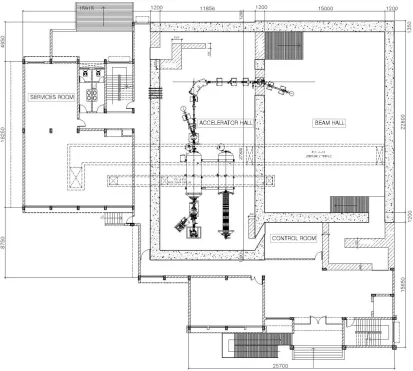
From radiation shielding objective and operational support requirement, facility with overall plan dimension 46.371 x 40.65m consists of mainly two blocks: (i) Accelerator hall and Beam hall (ii) Surrounding RCC framed structure.
Accelerator and Beam halls with plan dimension 27.3 x 11.856m and 22.6 x 15.0m, floor height of 8.7m and 9.3m respectively, consist of 1.2m thick RCC shielding walls and RCC roof slab above of 0.75m thickness.
Surrounding structure comprises of three floors (Ground+2) of height 4m each, houses vital facilities like Control room, Data room, Health physics lab, Detector lab, Vacuum lab, Target lab, Chemistry lab, Accelerator component service room and other allied facilities required for operation of plant.
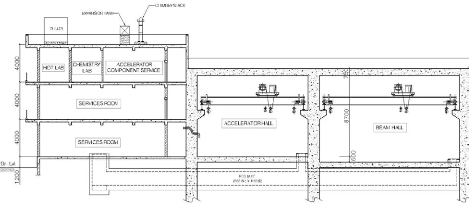
The facility located in seismic zone III with probable seismic intensity VII is founded on Type III soft soil through bored cast in-situ pile foundation with pile length 25m from existing ground level. Geometry, stiffness and mass distribution is asymmetric about three cardinal directions. Ground floor plan and longitudinal section of building is shown in Figure 1 and 2.
Figure 2. Longitudinal Section
FACILITY CATEGORIZATION
The safety objective for nuclear installations is to protect individuals, society and the environment from harm by establishing and maintaining effective defences against radiological hazards. To meet the safety requirements of NFOPs, graded approach for design is
(i) To identify the safety functions to be performed by the item to ensure plant safety in operational states as well as during and post accidental conditions.
(ii) Consequences of failure of item to perform the safety function.
(iii) Frequency at which the item will be called upon to perform a safety function.
Depending upon safety functions to be performed, facility is classified on the basis of safety, seismic and design requirement.
Safety Hazard Class
Facility under consideration is classified as safety class 3 i.e. low hazard, having potential for significant on-site radiological contamination.
Seismic Category
In terms of its importance to safety in the event of an earthquake, building falls under seismic category 2 i.e. safety systems during and after an external event do not interact with items in the safety group of external events.
Design Class
Based on safety classification, seismic categorization and ‘single parameter control’ approach, facility to be designed for Design class 3 (DC3) as per table II of Tecdoc 1347 where non-collapse of structure to be maintained by allowing for inelastic behavior.
ANALYTICAL APPROACH
Numerical Model
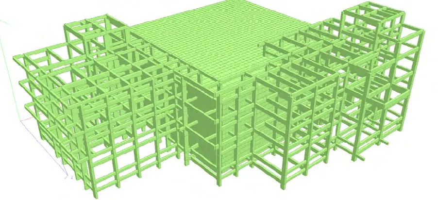
A three-dimensional finite element mathematical model using beam and 4-noded plate elements is developed on STAAD.Pro to represent the spatial distribution of mass and stiffness of shielding and non-shielding structure, keeping provision for alternate option of connectivity at interface.
Pile-structure interaction effect is considered by modeling pile as equivalent spring at column-pile cap junction with spring stiffness calculated from depth of pile fixity below ground level as per IS: 2911 (Part 1/Sec 2).
Figure 3. 3D rendered view of structural model
Interface Connections
Interface connections between radiation shielded area and surrounding structure are idealized by modeling a mass-less interaction spring with spring rigidity corresponding to type of connection as shown in Figure 4.
Four models to simulate four types of interface connections between shielded and non-shielded structure are developed keeping geometrical properties of structural members and loading same in all the models. The interface connections studied are:
1. Roller connection 2. Pinned connection 3. Rigid connection
4. Rigid connection with peripheral concentric braced frames
Structural Analysis
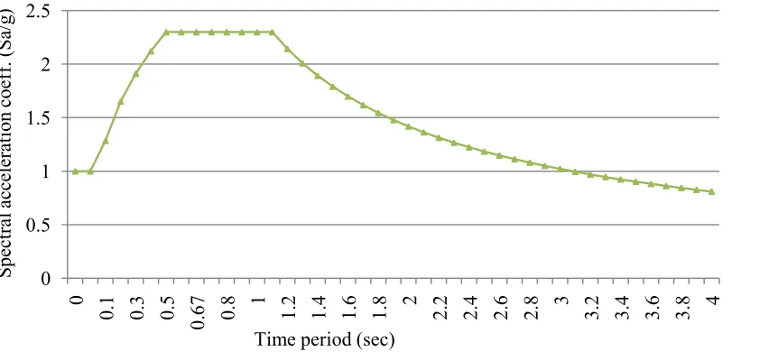
Seismic analysis is carried out by linear elastic dynamic response spectrum approach (RSA) with design free-field acceleration for firm bearing strata of 0.1gusing normalized design response spectra for design intensity level 1, soil type-3 and 5% damping as per Tecdoc-1347. Design basis ground motion in vertical direction is taken as 2/3rd of corresponding value along horizontal direction as per IS 1893 (part
4). The number of modes included in the calculation of response for each principal direction is such that cumulative modal mass of all the modes considered is at least 90% of total seismic mass. To take into account non-participating mass of higher modes, missing mass correction is applied corresponding to highest spectral acceleration in interval between cut-off frequency and zero period acceleration. The response contribution of individual modes is combined by Complete Quadratic Combination method (CQC) to determine the total response of structure to the ground motion. Final seismic response in each principal direction is multiplied by correction factor of 1.2 corresponding to irregular buildings as per table XII of Tecdoc-1347. Simultaneous peak seismic response from three components of earthquake motion is combined using Newmark rule 100:40:40 including sign variations.
Figure 5. Normalized design response spectra for design intensity level 1, soil type-3 and 5% damping
Static accidental torsional load due to eccentricity of 5% of floor plan dimension perpendicular to the direction of earthquake force is considered to account for torsional moments coming from unmodelled stiffness or unpredictable distribution of live load mass or possible torsional ground motion. This static torsional load is treated as separate load case consisting of two sub-load cases, one that produces clockwise moments and other anti-clockwise moments and is appropriately combined with seismicloads.
Structure is analyzed for all the basic load cases i.e. dead load, imposed load, crane load, earthquake load and load combinations as per Table 3.1 of AERB/SS/CSE-1.
0 0.5 1 1.5 2 2.5
0
0.1 0.3 0.5 0.67 0.8 1 1.2 1.4 1.6 1.8 2 2.2 2.4 2.6 2.8 3 3.2 3.4 3.6 3.8 4
Spect
ral
ac
ce
ler
at
ion
coe
ff
. (
Sa/
g)
RESULTS AND DISCUSSIONS
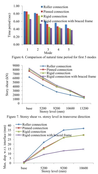
Influence of interface connection between radioactive and inactive area on seismic response of structure viz. mode shapes and frequencies, base shear, deflection pattern, torsional effect and seismic demand is examined in detail and the results of study are illustrated in Figures 6 to 8 and Table 1.
Figure 6. Comparison of natural time period for first 5 modes
Figure 7. Storey shear vs. storey level in transverse direction
Figure 8. Relative displacement vs. storey level in transverse direction 0.00 0.20 0.40 0.60 0.80 1.00
1 2 3 4 5
Tim e per iod (se c) Mode Roller connection Pinned connection Rigid connection
Rigid connection with braced frame
0 1000 2000 3000 4000 5000 6000 7000 8000 9000
base 5200 9200 10600 13200
Roller connection Pinned connection Rigid connection
Rigid connection with braced frame
Storey level (mm)
Stor y she ar (k N ) 0 5 10 15 20 25 30 35 40
base 5200 9200 10600
Roller connection Pinned connection Rigid connection
Rigid connection with braced frame
Storey level (mm)
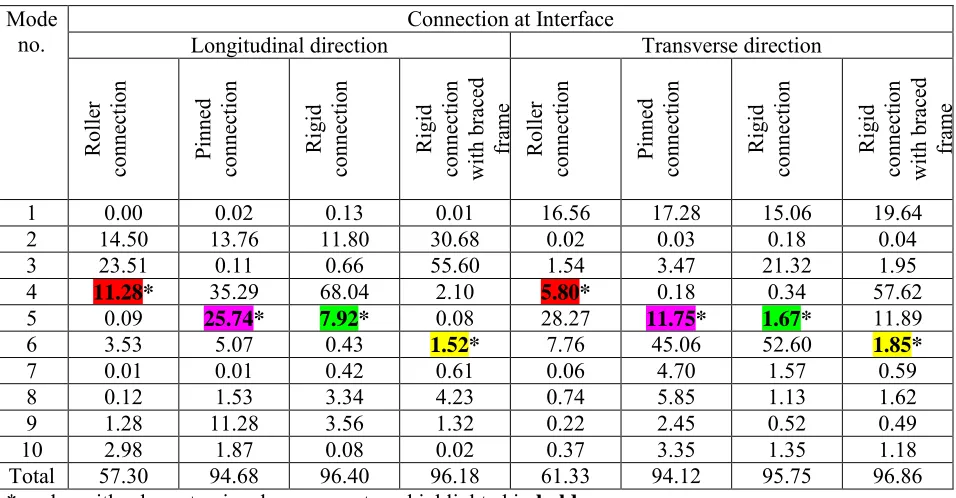
Table 1: Comparison of Mass participation (%) between different interface connections
Mode
no. Longitudinal direction Connection at Interface Transverse direction
R ol le r conne ct ion Pinne d conne ct ion R igi d conne ct ion R igi d conne ct ion w ith b rac ed fr am e R ol le r conne ct ion Pinne d conne ct ion R igi d conne ct ion R igi d conne ct ion w ith b rac ed fr am e
1 0.00 0.02 0.13 0.01 16.56 17.28 15.06 19.64
2 14.50 13.76 11.80 30.68 0.02 0.03 0.18 0.04
3 23.51 0.11 0.66 55.60 1.54 3.47 21.32 1.95
4 11.28* 35.29 68.04 2.10 5.80* 0.18 0.34 57.62
5 0.09 25.74* 7.92* 0.08 28.27 11.75* 1.67* 11.89
6 3.53 5.07 0.43 1.52* 7.76 45.06 52.60 1.85*
7 0.01 0.01 0.42 0.61 0.06 4.70 1.57 0.59
8 0.12 1.53 3.34 4.23 0.74 5.85 1.13 1.62
9 1.28 11.28 3.56 1.32 0.22 2.45 0.52 0.49
10 2.98 1.87 0.08 0.02 0.37 3.35 1.35 1.18
Total 57.30 94.68 96.40 96.18 61.33 94.12 95.75 96.86
*modes with a large torsional component are highlighted in bold
Of all the cases examined to know the implications at interface of shielded and non-shielded area, numerical results indicate that rigid connection with peripheral braced frames has significant reduction in maximum displacement w.r.t. interface, minimum amount of torsion in the mode shapes associated with the lower frequencies of the structure, substantially less amount of mass participation in torsional modes, thus result in controlling the lateral-torsional coupling of structure in contrast to other interface connections.
CONCLUSION
In this paper, roller, pinned and rigid connections are considered at interface between radioactive and inactive area for seismic study. In a nutshell, the analytical study shows that rigid connection between shielded and shielded structure with vertical steel bracing in selected bay of peripheral frames of non-shielded area is the simplest and highly effective alternative in reduction of seismic effects like seismic demand on interface elements, torsional effect on overall response, out of phase movement and pounding effect between two parts of structure. Finally, it is worth noting to provide peripheral braced frames in non-shielded area to mitigate seismic demand in interconnected safety systems, wherever clear seismic gap is unavoidable.
REFERENCES
AERB/SS/CSE-1 (2001). Design of concrete structures important to safety of nuclear facilities, Atomic Energy Regulatory Board, Mumbai
IAEA-TECDOC-1347 (2003). Consideration of external events in the design of nuclear facilities other than nuclear power plants, with emphasis on earthquakes, International Atomic Energy Agency, Vienna, Austria
IS 1893-part 4 (2005). Indian Standard Criteria for Earthquake resistant design of structures – Industrial structures including stack-like structures, Bureau of Indian Standards, New Delhi