12402 |
P a g e
Design Study Thin Film Multi-Cavity sharpness
pulses applied in communications Field
Amer B.Dheyab
1, Gaillan H. Abdullah
2,, Ali Hassan
3,Haider Y. Hammod
4Ministry of science and technology/Directorate of material Research /center of laser research1, 2, 3, 4
ABSTRACT: We present design thin film multi-cavity sharpness pulses applied in communications Field. These fil-ters are most widely used filtration technologies that made possible technical advancement of modern optical commu-nication system.This paper is concerned with a theoretical study on optoelectronics physics to design and analyze this type of filter. A brief introduction to the thin film sharpness pulses applied in communications Field. Technology will be presented. The recent progress in design thin film multi-cavity technology will be reviewed. These designs consist of two material TiO2 / SiO2 as high / low index. The wavelength range 710 - 1025nm and detecting number of channels
(20channels) at different wavelengths. The filter is to be coated on substrate Fused Silica having index 1.55 and the design operates at incident angle (450).
KEYWORD: Multi-cavity, thin film, optical communication, coating,
I.
INTRODUCTIONIn current optical communication systems multilayer thin-film coatings find application in many functions such as anti-reflection coatings, wavelength division multiplexing (WDM) filters, interleaves, band splitting filters, or gain flatten-ing filters. The fabrication of thin-film coatflatten-ings is a proven technology and packagflatten-ing technology has improved signifi-cantly in recent years [1-4]. A wide range of synthesis approaches is available to design multilayer coatings even with complex reflection and transmission profiles such as gain equalizing filters for erbium-doped fiber amplifiers (EDFAs) [1- 6]. Recently, emphasis has been given to designing coatings with a decreased sensitivity to fabrication errors allow-ing a higher yield [7, 8]. Progress has also been made in thermo-optic and electro-optic tunallow-ing of thin-film filters [9- 11]. In the following we will focus on the dispersive properties of thin-film coatings, since these gain importance in the design of filters for dense wavelength division multiplexing (DWDM) systems and are promising for novel multiplex-ing/demultiplexing and dispersion-compensation components. Thin film multi-cavity sharpness pulses applied in com-munications Field are widely used in wavelength division multiplexing (WDM) applications in fiber optic communica-tion systems. These filters must have sharp cut-on and cut- off on either side of the sharpness pulses and practically zero transmittance outside the sharpness pulses, over the wavelength range of the applications. Wavelength division multiplexing (WDM) is an integral component of fiber optic communication systems and enables several channels of information to be encoded on light signals of different wavelengths and transmitted simultaneously over the same opti-cal fiber, to separated and decoded at the receiving end [12].
II.
THEORYThe basic structure of thin film multi-cavity sharpness pulses applied in communications field is a multilayer stack of alternately high index and low index thin films, most of which are one-quarter wave thick at the design wavelength, deposited on an ophthalmic glass or silica substrate'. TiO2 is chosen as the high index material and SiO2 as the low
12403 |
P a g e
Air /HLHLH100LHLHLHLHLHLH 100LHLHLH/glass End Spacer Coupling Spacer End reflector layer reflector layer reflector
With the high index (TiO2) and low index (SiO2) layers being one quarter wave thick at 900 nm. The technology of
DWDM is one of the most recent and important technique in the development of fiber optic communication technolo-gy. In the following section we briefly describe the stages of fiber optic technology and the place of DWDM in the de-velopment. The reality of fiber optic communication had been proven in the nineteenth century, but the technology began to advance rapidly in the late of the twentieth century. After the probability of transmitting light in fiber had been established, it was known that light has an information- carrying capacity of 10,000 times greater than the highest radio frequencies. Besides, the additional advantages of fiber optic communication over copper wire include the ability to carry signals over long distances, low error rates, immunity to electrical interference, security, and light weight. Multip-lexing and demultipMultip-lexing functions both employ sharpness pulses applied in communications Field, cascaded and combined in other ways to achieve the desired result. A different technology uses interference filters in devices called thin interference filters. Thin-film filters consist of a number of alternate layers of transparent dielectric mate of high and low refractive indices deposited sequentially on an optical substrate. The stack of thin films can be made using one of the coating technologies, such as plasma deposition, and ion assisted deposit long stability, and small losses of chromatic dispersion and polarization system, a thin-film filter would only transmit the wavelength of the optical chant he filter and would reflect all others in the DWDM signal. the theory and/or the proposed method band-pass filter is constructed on the Fabry wavelength, deposited on an ophthalmic glass or silica probability of transmitting light in fi-ber had been established, it information-carrying capacity of 10,000 times greater than the highest radio prism. Thin-film filters so multilayer plasma-assisted deposition, ion beam sputtering deposition (IAD). Thin-Thin-film filters exhibit a very low temperature coefficient, polarization-related dispersion. In DWDM channel which was designed for the filter and would reflect all others in the DWDM signal. Now we can use the heuristic model equation (1) for the maximum shift to estimate the maximum number of channels given the refractive indices of the two materials used, the stack thickness, the incidence angle, the polarization, and the operating wavelength. Account is the number of channels through the equation below:
𝑁
𝑐𝑙𝑎𝑛𝑛𝑒𝑙𝑠≤ 1 +
𝐿𝜆𝐶 8 𝐶𝑐𝑟𝑜𝑠𝑠𝑡𝑎𝑘
∆𝑛
𝑁𝑎𝑣𝑔2
𝜋 sin(𝜃)
2
1 −
sin (𝜃)2𝑁𝑠2
….. (1)
It is interesting to note that for a given set of materials, incidence angle, and adjacent channel crosstalk, everything on the right hand side except for the ratio of the stack thickness L to the wavelength λ is fixed, a 45º incidence angle, and alternating SiO2 and TiO2 layers, the number of channels can be estimated by (2).
𝑁
𝑇𝑖𝑂2,𝑆𝑖𝑂2,450≤ 1 + 0.53
𝐿𝜆𝐶
……….… (2)
Where:
12404 |
P a g e
lexing has been demonstrated theoretic using open filter. [15]. It is interesting to note that the number of channels scales as the thickness divided by the wavelength. just as we would expect. In this model the thickness not the number of layers seems to matter. That is not correct though, since the layer thickness should be on the order of a quarter wave-lengths. Therefore, fixing a stack thickness also fixes the number of layers needed.Finally, let us consider the design
question posed at the beginning Can we design a structure that demultiplexes 100 channels, changing to a larger incidence angle could also help to obtain more channels.
III. DESIGN AND DISCUSSION
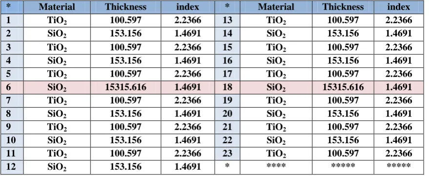
In the present work, these theoretical designs have been suggested and their profiles have been fully studied for the visible region and near IR region using open filter software [13]. The technology of DWDM is one of the most recent and important technique in the development of fiber optic communication technology.The sharpness pulses filter used for detecting light atdifferent wavelengths as in design below. Between these wavelengths the filter is as in Fig.1 the filter is to be coated on Fused Silica having index 1.55. The filter operates at incidence angle 45º. The most common structure for sharpness pulses applied in communications field, consisting of dielectric filter with quarter-wave optical thick layers for the layers and half-wave optical thick, or multiple half-wave optical thick layers for the spacers. So that the open filter program can be used to design this filter. Table.1 shows the data for the design.
Table. 1: shows the structure layers design
* Material Thickness index * Material Thickness index
1 TiO2 100.597 2.2366 13 TiO2 100.597 2.2366
2 SiO2 153.156 1.4691 14 SiO2 153.156 1.4691
3 TiO2 100.597 2.2366 15 TiO2 100.597 2.2366
4 SiO2 153.156 1.4691 16 SiO2 153.156 1.4691
5 TiO2 100.597 2.2366 17 TiO2 100.597 2.2366
6 SiO2 15315.616 1.4691 18 SiO2 15315.616 1.4691
7 TiO2 100.597 2.2366 19 TiO2 100.597 2.2366
8 SiO2 153.156 1.4691 20 SiO2 153.156 1.4691
9 TiO2 100.597 2.2366 21 TiO2 100.597 2.2366
10 SiO2 153.156 1.4691 22 SiO2 153.156 1.4691
11 TiO2 100.597 2.2366 23 TiO2 100.597 2.2366
12 SiO2 153.156 1.4691 * **** ***** *****
12405 |
P a g e
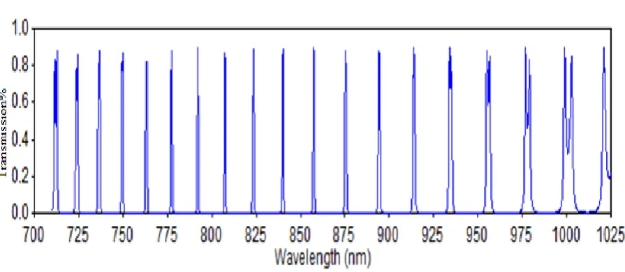
Fig. (1): Transmission vs. wavelength for design multi-cavity sharpness pulses filter with two cavities
IV .
CONCLUSIONSFrom the results above we can conclude that Multilayer thin-film coatings are a proven technology that is employed in many areas of optical communication systems. New developments include the design of filters with a higher tolerance towards fabrication errors, tunable filters, and dispersive filters for dispersion compensation and wavelength multiplex-ing and demultiplexmultiplex-ing. The goal of this talk is to give an overview of how design study thin film multi-cavity sharp-ness pulses applied in communications Field., where optical thin film filters fit in, and what it takes to make them ap-plications of multi-cavity filters such as space-based laser communication systems, spectral radiometry, medical diag-nostics, chemical analysis colorimetry, environmental monitoring, security systems, avionics, space and ground base telescopes, and others
.
REFERENCES
[1] H. A. MacLeod, "Thin-Film Optical Filters", Institute of Physics Publishing (2001).
[2] R. B. Sargent, “Recent Advances in Thin Film Filters,” OFC 2004 Technical Digest, TuD6 (2004).
[3] G. J. Ockenfuss, N. A. O’Brien, and E. Williams, “Ultra-low stress coating process: an enabling technology for extreme performance thin film interference filters,” Post deadline Papers, FA8 (2002).
[4] T. Honda, A. C. Liu, J. Valera, J. Colvin, K. Sawyer, R. R. McLeod, “Diffraction-compensated free-space WDM add-drop module with thin-film filters,” IEEE Photonics Techn. Lett.15/1, 69-71 (2003).
[5] A. Thelen, "Design of Optical Interference Coating", McGraw-Hill (1989).
[6] J. A. Dobrowolski and R.A. Kemp, “Refinement of optical multilayer systems with different optimization procedures,” Appl. Opt., 29/19, 2876-2893 (1990) and references herein.
[7] A. Thelen, M. Tilsch, A. V. Tikhonravov, M. K. Trubetskov, U. Brauneck, “Topical Meeting on Optical Interference Coatings (OIC’2001): de-sign contest results,” Appl. Opt.,.41/16, 3022-3038 (2002).
[8] P. G. Verly, “Design of a robust thin-film interference filter for erbium-doped fiber amplifier gain equalization,” Appl. Opt.,.41/16, 3092-3096 (2002).
[9] M. Lequime, R. Parmentier, F. Lemarchand, C. Amra, “Toward tunable thin-film filters for wavelength division multiplexing applications,” Appl. Opt.,.41/16, 3277-3284 (2002).
[10] L. Domash, M. Wu, N. Nemchuk, E. Ma, “Tunable and switchable multiple-cavity thin film filters,” J. LightwaveTechn., 22/1, 126-1235 (2004). [11] D. J. Moss, M. Lamont, S. McLaughlin, G. Randall, P. Colbourne, S. Kiran, C. A. Hulse, “Tunable Dispersion and Dispersion Slope Compensa-tors for 10 Gb/s Using All-Pass Multicavity Etalons,” IEEE Photonics Techn. Lett.,15/5, 730-732 (2003).
12406 |
P a g e
C230 (2008).
[14] M. Gerken and D. A. B. Miller, “Wavelength Demultiplexer Using the Spatial Dispersion of Multilayer Thin-Film Structures,” IEEE Photonics Techn.Lett.15/8, 1097-1099 (2003).
[15] used open filter software.
BIBLIOGRAPHY
amer badr Dheyab was born in Baghdad ,Iraq in 1987, he received B.S degree in physical science from University of Technology ,in 2011,. She joined to the Laser and Optoelectron-ic center in Ministry of Science and Technology in 2013,and carried out research in Thin films design system and optical design.
Gaillan Husein Abdullah was born in Baghdad ,Iraq in 1963, he received B.S degree in physical science from Baghdad University,in1986,M.S degree in Laser and optoelectronics (Alrasheed College / university of Technology-Baghdad) in 2002and he Ph.D degree in laser and optoelectronics Technology from Technology University /Iraq-Bagdad in 2010. She joined to the Laser and Optoelectronic center in Ministry of Science and Technology in 2009,and carried out research in Thin films design system and optical design.
Ali Hassan Jabur was born in Baghdad, Iraq in 1958, he received B.S degree in physical science from Baghdad University, in1983. He joined to the Laser and Optoelectronic cen-ter in Ministry of Science and Technology in 1992, and carried out research in design thermal camera and optoelectronics