THE APPLICATION OF ASME CODE CASE N-284 FOR BUCKLING
SAFETY EVALUATION
Laiyun Chen1, Honghui Ge2, and Shenghua Liu3
1
Junior Engineer, Shanghai Nuclear Engineering Research & Design Institute (SNERDI), Shanghai, China ([email protected])
2
Chief Engineer, SNERDI, Shanghai, China
3
Senior Engineer, SNERDI, Shanghai, China
ABSTRACT
Based on the study of ASME code case N-284 about metal containment shell buckling design, a simplified method for buckling safety evaluation for steel containment head of the advanced pressurized-water reactors is presented and described in this paper. Meanwhile, the buckling evaluation macro is developed by using ANSYS parameter design language. Then the buckling safety for the steel containment head of the advanced nuclear plant under the severe accident condition is estimated.
INTRODUCTION
The design of a class MC containment vessel against buckling shall be based on the requirements of Subsection NE of ASME code. But the design rules given by NE-3133 are specific for unstiffened or ring stiffened cylindrical shells, spherical shells and formed heads under external pressure and unstiffened cylinders under axial compression. Although NE-3222.1(a) and (c) provide general guidelines for other shell geometries and loading conditions, it is very difficult for practical engineering application. In addition, many studies show that the actual buckling process of the thin shell structures is often accompanied with large deformation, and that the shell stress may reach to the elastoplastic level, which will lead to two kinds of nonlinearity coupling. The critical buckling stress is also sensitive to initial imperfections of the structure. Therefore the buckling analysis and evaluation for large metal containment structures is recognized to be difficult in the research and engineering application fields.
Based on the study of ASME code case N-284 about metal containment shell buckling design, a simplified method for buckling safety evaluation which is applicable to steel containment head of the advanced pressurized-water reactors is described in the paper. Meanwhile, the buckling evaluation macro is developed by using ANSYS parameter design language (APDL). Taking the large steel containment vessel of the advanced nuclear plant as an example, by using the simplified method and the buckling assessment module introduced in the paper, the buckling safety for steel containment head under the severe accident condition is then estimated, which help to understand the buckling behavior of containment head and also provide reference for safety review of the steel containment vessel.
A SIMPLIFIED METHOD FOR BUCKLING SAFETY EVALUATION
containment head of nuclear plant is evaluated.
Critical Buckling Stress
The theoretical buckling values correspond to the minimum values determined from theoretical equations for shells with classical simple support boundary conditions under uniform stress fields. In order to consider more complex shell geometries and load conditions, this paper conducts the linear bifurcation buckling analysis for steel containment head by using general finite element program to get the minimum eigenvalue coefficient
for critical buckling stress, and thereby the real buckling mode of steel containment head is also captured for better understanding of buckling behavior.Factor of Safety
Factor of safety is defined as the ratio of the theoretical buckling value reduced by capacity reduction factor to the basic compressive allowable stress referred to by NE-3222.1. According to N-284-1400 and NE-3222.2, factor of safety FS, corresponds to the following:
(1) For Design Conditions and Level A and B Service Limits, FS=2.0. (2) For Level C Service Limits, FS=1.67.
(3) For Level D Service Limits, FS=1.34.
2.3 Capacity Reduction Factor
The buckling capacity of ideal shells can be determined by linear bifurcation analysis. But for actual shells, the reduction in capacity due to imperfections and nonlinearity in geometry and boundary conditions should be considered. According to N-284-1513, the capacity reduction factor
iL(i1, 2) for steel containment head is given below for shells which meet the tolerances of NE-4220:
1L min 2L/ 0.6, 0.75
(1)
2
0.6
0.627
0.837 0.14
0.826
1.73 23.6
0.124 23.6
L
M
M M
M M
M
<1.5
1.5 <1.73
(2)
where
1L corresponds to uniaxial compression and
2L corresponds to biaxial compression. And thefactor M is equal to /l Rt and is suggested to be a constant for certain containment head, where lis
the supporting length for head in meridional direction, R is shell radius, and t is shell thickness.
2.4 Plasticity Reduction Factor
If the stress components (meridional compressive stress) or (circumferential compressive
stress) of shell elements exceed a certain limit under the actual load condition, the failure of elasto-plastic instability may occur, thus plasticity reduction factor is recommended to account for the non-linear
material properties. According to N-284-1620, the value of plasticity reduction factor
i(i , ) forcontainment head can be calculated corresponding to the different stress conditions:
1.0 0.55 0.18
0.55< 1.6
0.45 1
1.31-1.15 1.6< <6.25 (3)
(2) Circumferential compression
1.0 0.67
2.53-2.29 0.67< 1.0
(4)
(3) When the containment head bears meridional compression plus circumferential compression,
the smaller value of and which are calculated from the above equation (3) and
equation (4) respectively, is applied.
where i
y
FS
, and y is the yield strength of the material.
2.5 Buckling Evaluation Rule
The elements of containment head may be in axial compression or biaxial compression under the actual load condition. If shell stress is within the material proportion limits, only the elastic buckling instability may happen, otherwise it would lead to elasto-plastic buckling instability. On the basis of N-284, the simplified buckling evaluation rule is proposed below for containment head:
(1) During elastic stage
1.2 iL
FS
(5)
(2) During elastic-plastic stage
1.2 iL i
FS
(6)
3. BUCKLING EVALUATION FOR STEEL CONTAINMENT HEAD
3.1 Buckling Evaluation Module Based On APDL
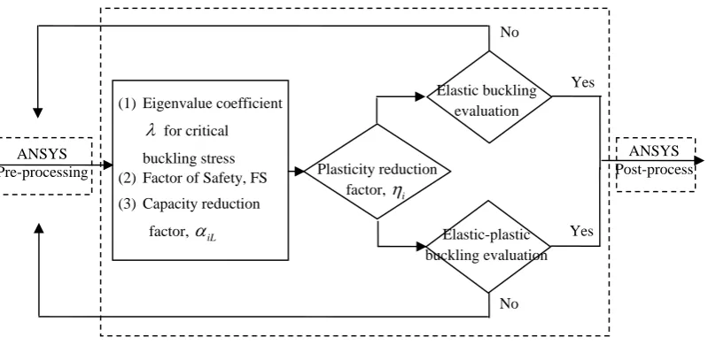
Program module of buckling safety assessment for the containment head of nuclear power plant is developed by using APDL, which is shown in figure 1. Firstly to calculate shell stresses of containment head under the actual load condition, then factor of safety, capacity reduction factor and plasticity reduction factor are determined respectively per the paper, at last the buckling safety assessment for containment head of nuclear power plant is proceeded.
3.2 Finite Element Calculation Input
steel containment head for buckling evaluation.
Figure 1. Program module for buckling safety assessment
Figure 2. Finite element model of steel containment head
3.3 Buckling Evaluation
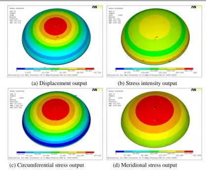
The output of solution results for steel containment head under the severe accident is shown in figure 3. Figure 3(a) shows that the displacement at the top point of steel containment head is 63mm, and figure 3(b) shows that the stress intensity at the knuckle between head and cylinder is 285MPa, which is less than the stress intensity limits at the level C service limits specified in subsection NE and meets the requirements of 10 CFR 50.34. However, the compressive stress is occurred in the circumferential direction of the knuckle of steel containment head from 3(c) and 3(d), and it reaches to 140MPa. Therefore the buckling safety assessment for the head should be performed.
ANSYS Pre-processing
(1) Eigenvalue coefficient
for critical buckling stress (2) Factor of Safety, FS
(3) Capacity reduction
factor, iL
Plasticity reduction factor, i
Elastic buckling evaluation
Yes
Yes No
ANSYS Post-process
(a) Displacement output
(b) Stress intensity output
(c) Circumferential stress output
(d) Meridional stress output
Figure 3. The output of solution results for steel containment head under the severe accident
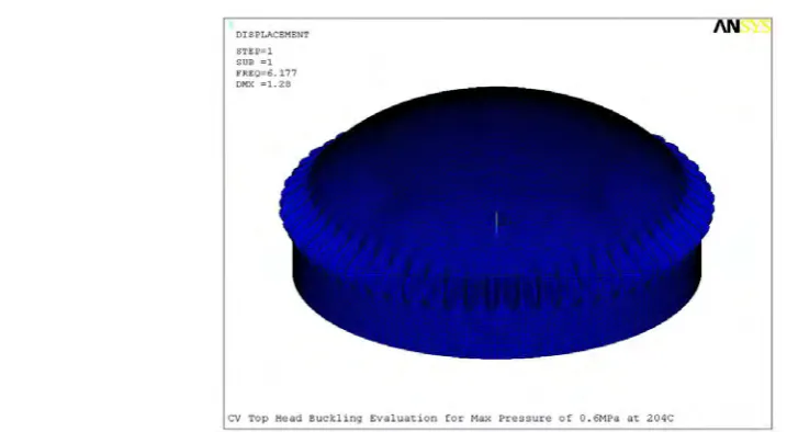
Following the simplified method introduced in the above section and the buckling evaluation module developed by APDL, the buckling safety assessment for steel containment head is conducted. The first buckling mode for the containment head of the advanced plant under the dead load plus internal pressure of 0.6MPa is shown in figure 4, which gives the linear bifurcation eigenvalue of 6.177 for the
critical buckling stress. The values of FS, 1L and are calculated as 1.67, 0.35 and 0.956 respectively.
And then by putting the resulting values of , FS, 1L and in the equation (6), it obtains that
6.177 0.35 0.956
1.24 1.2 1.67
iL i
FS
Figure 4. Linear bifurcation buckling mode of the steel containment head
4. CONCLUTION
Based on the study of ASME Code Case N-284 about metal containment shell buckling design, a simplified method which is applicable for containment head of the advanced pressurized-water reactors for buckling analysis and evaluation is provided in the paper. Meanwhile, the buckling evaluation macro is developed by using APDL, and the buckling safety for the steel containment head of the advanced nuclear plant under the severe accident condition is then evaluated, the results show that:
(1) The method and the program module for buckling safety evaluation for containment head of
nuclear power plant proposed in the paper are reasonable, which are suitable for practical engineering application.
(2) The buckling failure of steel containment head of the advanced plant would not appear under
the severe accident, and it can maintain the pressure boundary integrity.
(3) As Code Case N-284 for shell buckling design is conservative and the influence of internal
pressure on a shell structure may reduce the initial imperfections, so higher values of capacity reduction factors is recommended for practical engineering application if there is adequate demonstration.
REFERENCES
American Society of Mechanical Engineers (ASME). (2007). “Class MC Components, Rules for
Construction of Nuclear Facility Components,” ASME Boiler & Pressure Vessel Code III Division
1-Subsection NE, New York.
American Society of Mechanical Engineers (ASME). (2007). “Case N-284: Metal Containment Shell
Buckling Design Methods, Class MC,” Code Cases: Nuclear Components, New York.
Galletly, G D. (1978). “Elastic and Elastic-Plastic Buckling of Internally – Pressurized 2:1 Ellipsoidal
Shells,” ASME Journal of Pressure Vessel Technology, 100: 335-343.
Timoshenko, S.P. and Gere, J.M. (1961). Theory of Elastic Stability. McGraw-Hill Book Co. Inc.
U.S. Nuclear Regulatory Commission. (2011). “Contents of applications; technical information,” 10 CFR
50.34.
U.S. Nuclear Regulatory Commission. (2007) “Standard Review Plan: Section 3.8.2 Steel Containment
Vessel,” NUREG-0800, Washington DC.
Westinghouse Electric Company LLC. (2011). “Design of Structures, Components, Equipment and