20th International Conference on Structural Mechanics in Reactor Technology (SMiRT 20) Espoo, Finland, August 9-14, 2009 SMiRT 20-Division 5, Paper 3192
1
Response and Seismic Margin of Kashiwazaki Kariwa Nuclear Power Plant
Building during Chuetsu-oki Earthquake
Atsushi Suzuki
d, Rikiro Kikuchi
a, Takayuki Koyanagi
b, Minoru Kanechika
c,
and Yoshinori Mihara
eaNuclear Asset Management Department, Tokyo Electric Power Company, 1-1-3, Uchisaiwai-cho, Chiyoda-ku, Tokyo
100-8560, Japan, kikuchi.rikiro@tepco.co.jp b
Nuclear Asset Management Department, Tokyo Electric Power Company, 1-1-3, Uchisaiwai-cho, Chiyoda-ku, Tokyo 100-8560, Japan, koyanagi.takayuki@tepco.co.jp
cNuclear Power Department, Kajima Corporation, 6-5-11, Akasaka, Minato-ku, Tokyo 107-8348, Japan,
kanechika@kajima.com
dNuclear Power Department, Kajima Corporation, 6-5-11, Akasaka, Minato-ku, Tokyo 107-8348, Japan, a-suzuki@kajima.com
e
Nuclear Power Department, Kajima Corporation, 6-5-11, Akasaka, Minato-ku, Tokyo 107-8348, Japan, y-mihara@kajima.com
Keywords: Niigataken Chuetsu-oki earthquake, Nuclear Power Plant, Seismic design, Seismic margin, Shear wall
1
ABSTRACT
The maximum response of the reactor buildings of Kashiwazaki-Kariwa nuclear power plant observed during the Niigata-ken Chuetsu-Oki Earthquake, which occurred on July 16, 2007 was larger than the earthquake for seismic design. Nevertheless, there was no large damage to the power plant facilities or buildings. Thus, it is considered that integrity was ensured. One of the reasons would be that the design of the facilities incorporated appropriate margins. The responses of shear walls were estimated in this study from the simulation analyses on seismic response using records observed during the earthquake. Thus, the reasons why facility’s integrity was secured were investigated by comparing the estimated responses with the design load. They were found to be as follows. The design incorporated static seismic load three times larger than those for ordinary buildings. A further margin was added to the static design seismic force in actual design practice. Also, the design incorporated a margin for the reinforcing bar arrangement. These integrated effects were considered to ensure that the response due to Chuetsu-Oki Earthquake did not damage the shear walls and maintained the behavior within the elastic range.
2
INTRODUCTION
The maximum response observed in the reactor buildings of Kashizaki Kariwa Nuclear Power Plant during the Niigata-ken Chuetsu-oki earthquake (NCO, hereafter) in 2007 exceeded the earthquake for seismic design. However, the structural members were generally maintained within the elastic range, so it was considered that their integrity was ensured. This report discusses the causes of this by comparing the design force with the actual seismic force imparted by the Chuetsu-Oki earthquake.
3
STRUCTURE OF NUCLEAR REACTOR BUILDING
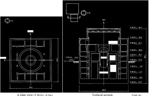
Reactor building Unit 6 was investigated in this study. Its major structure is of reinforced concrete, with four stories above ground and three stories under ground. The structure under ground was embedded about 25m and the mat foundation 5.5m thick was installed on the rock Tertiary formation. Total weight of the building was about two million kN.
2
Its main shear walls are external box type walls and interior walls, and it is designed as a reinforced concrete containment vessel (RCCV). The shear walls resisted the horizontal force that acted on the building during the earthquake.
A plan view (T.M.S.L.-8.2m) Vertical section (Unit: m)
* T.M.S.L: Tokyo Mean Sea Level
Figure 1 Reactor building Unit 6 at Kashiwazaki-Kariwa Nuclear Power Plant
4
DESIGN SEISMIC LOAD OF NUCLEAR REACTOR BUILDING
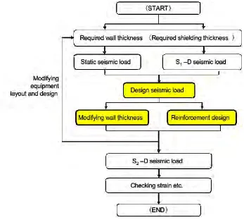
The design flow for the nuclear buildings is shown in Figure 2. Wall thickness is normally determined in the equipment layout design for required thickness and to ensure structurally sufficient earthquake resistance. The seismic load for the design of reactor building Unit 6 was determined to ensure sufficient earthquake resistance, taking into account both dynamic and static seismic loads (static seismic load : three times larger than that based on the Building Standards Law in Japan). The dynamic seismic load herein was calculated from the seismic response analysis using the basic design horizontal earthquake motion S1-D (195 Gal on the base mat of building Unit 6). Moreover, it is suggested in designing reactor buildings to investigate cases where larger earthquakes occur. This is to ensure that functions necessary to maintain safety even in cases of large earthquake ground motions are secured, such as safely shutting down the nuclear reactor, cooling down and confining radioactive material to prevent dispersion outside. As a result, the maximum acceleration on the base mat due to the basic design horizontal earthquake motion S2-D became 263Gal.
The design seismic loads ensured the tolerance by adding a margin to the seismic loads integrating dynamic and static seismic loads. The incorporated margin herein took into account the changes of various conditions adopted in the design. Also, it was within the range in which the effects of embedding about 25m under ground could be safely ignored, which was taken into account when calculating the static seismic force.
3
Figure 2 Design flow of a reactor building
! " # $ %
&'())#
* +,-./0
123# 1"34 %32 "#3$ "23" #$35 $"34 $23# %634
738393:3 ;)*
! " # $ %
Design seismic load
NCO S1-D
Static seismic load Design seismic load Shear stress during NCO
Static seismic load
S1-D
S2-D
Shear stress
S2-D
! " # $ %
&'())#
* +,-./0
123# 1"34 %32 "#3$ "23" #$35 $"34 $23# %634
738393:3 ;)*
! " # $ %
Design seismic load
NCO S1-D
Static seismic load Design seismic load Shear stress during NCO
Static seismic load
S1-D
S2-D
Shear stress
S2-D
4
5
COMPARISON WITH SEISMIC FORCE DUE TO CHETSU-OKI EARTHQUAKE
The seismic force acting on nuclear reactor building Unit 6 during the NCO (320 Gal at the base mat) was
estimated from an elastic seismic response analysis using the observation record1). The maximum shear
stresses during the NCO became larger than S1-D. However, it was at the same level or lower than the static seismic loads, and it was sufficiently lower than the design seismic loads.
The design seismic loads on the building’s structural members were less than the allowable forces, which maintained the members within the elastic range. Because the seismic force was lower than the design seismic force during the NCO, the building was considered to be within the elastic range.
It was considered that an earthquake ground motion larger than the reference earthquakes ground motion S1-D and S2-D, had acted. However, the margin adopted for the static / design seismic loads would have maintained the building’s integrity.
6
SHEAR FORCE TO BE RESISTED BY REINFORCING BARS IN SHEAR WALL
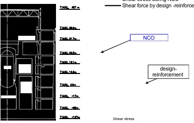
As shown in Figure 4, the shear force that reinforcing bars in the shear wall were designed to resist was larger than the shear force deemed to have acted during the Chetsu-oki earthquake. It is thus understood that a tolerance existed in designing the bar arrangement.
The shear wall was designed as follows. Its thickness was determined such that the seismic force could be resisted to some extent by the concrete only, while it satisfied shielding requirements. However, the design quantity of reinforcing bars was based on the assumption that the concrete did not resist the seismic force but that the reinforcing bars resisted the entire seismic force. This criterion was based on allowable stress under the loading such as earthquake. The required reinforcing bars were determined from structural considerations.
However, the final quantity was determined by incorporating the tolerance necessary to maintain continuity, constructability, etc. of reinforcing bar arrangement for the upper and lower stories. Furthermore, the RCCV was designed for the load for an assumed incident. Thus, there were cases where the quantity of reinforcing bars incorporated a tolerance when only seismic force was taken into account.
Shear stress during NCO
Shear force by design -reinforcement
! " # $ % &
'()**#+ ,-./01
234# 2"45 %43 "#4$ "34" #$4& $"45 $34# %645
748494:4 ;*+
NCO
design-reinforcement
Shear stress
5
7
RESPONSE ON SHEAR SKELETON CURVE
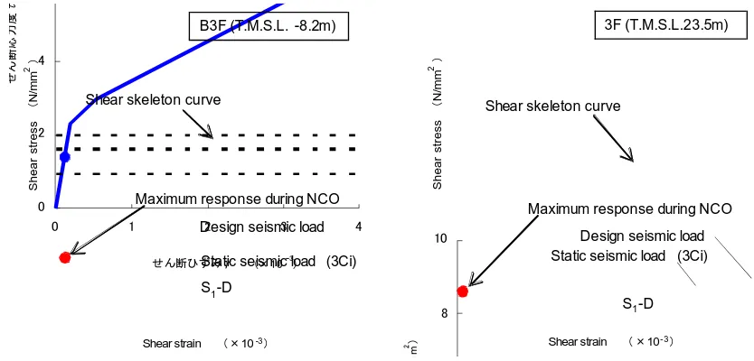
The seismic force caused by the Chuetsu-oki earthquake was estimated from elastic analysis. However, attempts were also made to estimate it from elasto-plastic analysis. The nonlinear characteristics (skeleton curve) of shear force of the shear walls were determined by the method specified in the guideline for seismic
design of nuclear power plants JEAG46012). The conditions assumed for the above were the same as those
for the elastic analysis.
Figure 5 shows the maximum response during the NCO overlaid on the skeleton curve. The results show that the response to the NCO was below the first turning point (concrete cracking point) and was considered to be within the elastic range. It was consistent with the fact that the seismic force during the NCO was below the design seismic loads.
! " # $ % &!
! & " ' #
( ) * + + " , -. / 0 1 2 3
-./4567 (8&!9',
! " # $ % &!
! & " ' #
-./4567 (8&!9',
( ) * + + " , -. / 0 1 2 3
B3F (T.M.S.L. -8.2m)
Shear skeleton curve
Static seismic load (3Ci) Design seismic load
S1-D
Shear strain (810-3:
S h e a r s tr e s s ( N /m m 2 :
Maximum response during NCO
3F (T.M.S.L.23.5m)
Shear skeleton curve
Static seismic load (3Ci) Design seismic load
S1-D
Shear strain ( 810- 3:
S h e a r s tr e s s ( N /m m 2 :
Maximum response during NCO
Figure 5 Maximum responses during NCO on shear skeleton curves
8
CONCLUSIONS
The response on the base mat showed that the earthquake ground motion caused by the Chuetsu-oki earthquake at reactor building Unit 6 was larger than the design load. However, the structural members of the building were considered to be within the elastic range.
This is considered to be because a static seismic loads three times that of ordinary buildings was assumed and a tolerance was incorporated into the design seismic loads. Furthermore, the effect of the tolerance was taken into account in designing the reinforcing bar arrangement. Thus, the behavior was considered to be within the elastic range. The above is consistent with the relationship between the hysteresis characteristics and the maximum response.
REFERENCES
1) Kikuchi, Rikiro et al.: “Simulation analysis on Kashiwazaki Kariwa nuclear reactor buildings due to Chuetsu-Oki earthquake (Parts 1 through 3)”, proceeding of academic speech of Architectural Institute of Japan, 2008