DOI: 10.15680/IJIRSET.2014.0312117
Copyright to IJIRSET www.ijirset.com 18127
Electronically Sensed Hydraulic Clutch – A
Review
R. Sabarish, S. Arumugavel,
Dr. J. Hameed Hussain3Assistant Professor, Department of Mechanical Engineering, Bharath University, Chennai, India.
Assistant Professor, Department of Mechanical Engineering, Sakthimariamman Engineering College, , Chennai, India. Professor, Department of Mechanical Engineering, Bharath University, Chennai, India
ABSTRACT: Electronic Clutch modification is for use by disabled drivers who prefer the control offered by a manual transmission but have difficulty operating the clutch pedal. The Device provides the driver with fingertip control of the clutch, removing the need for use of the left leg to perform gear changes. It is suitable for amputees or paraplegics, among others, especially in the case where an automatic model of a vehicle is not available.
By mounting the device on the gear stick, this modification allows the driver to operate the clutch with the left hand to make smooth gear changes. It replaces the original gear knob and incorporates a finger operated trigger lever and button. The aluminum trigger controls the clutch, with the pedal moving proportionally.
A handy switch provided with gear shift lever will operate a motor to control the functions of hydraulic cylinders by means of relay and two sensor switches. Hence fluid pressure produces in the hydraulic cylinder force the piston against spring force. This directing the clutch to engage and disengage for which fluid line will be should short circuited. This mechanism is unique in nature trouble free, cost effective and smart for its perfection.
I. INTRODUCTION
Clutch is a simple device which can be employed in any rotating drive system where it is necessary to disengage or re-engage the transmission of torque. A friction clutch is used for vehicle transmission systems. The clutch system consists of a driven and a driving member (Figure 5.25). In a transmission, the driving member is usually also the engine flywheel. The driven member is a friction disc which connects via a spline to the gearbox input shaft. The friction disc is clamped by a spring disc in the rest position, and hence drive and torque can be transmitted from driving to driven member. The spring clamping can be relaxed as required by the operator (in a vehicle transmission, via the clutch pedal); this allows the friction disc to spin freely and hence no torque is transmitted. If the spring pressure is gradually released, the clamping force can be gradually applied to the friction disc and hence torque can be progressively transferred between the driving and driven members as required. This allows the smooth take up of drive and transfer of torque between the engine and gearbox. The clutch in a vehicle transmission allows the effective disconnection of the engine and gearbox as required by the driver.
The power developed inside the engine cylinder is ultimately aimed to turn the wheels so that the motor vehicle can move on the road. The reciprocating motion of the piston turns a crankshaft rotating the flywheel thought the connecting rod. The circular motion of the crankshaft is no w to be transmitted t o the rear wheels. It is transmitted though the clutch, gearbox, universal joints, propeller shaft or drive shaft, differential and axles extending to the wheels.
DOI: 10.15680/IJIRSET.2014.0312117
Copyright to IJIRSET www.ijirset.com 18128
modern passenger cars and trucks, but its arrangement many vary according to the method of drive and type of transmission units.
Figure 1.1 Automobile Power Transmissions
Power transmissions system of an automobile shown in figure no1.1. The motion of the crank shaft is transmitted though the clutch to the gear box or transmission, which consists of a set of tears to change the speed. From gearbox, the motion is transmitted to the propeller shaft though the universal joint and then to the differential through another universal joint. Universal joint is used where the two rotating shafts are connected at an angle for power transmission. Finally, the power developed inside the cylinder is transmitted to the rear wheels though a system of transmission. The vehicle which have front wheel drive in addition o the rear wheel drives include a second set propeller shafts, universal joints, final drives and differentials for the front units.
II. TYPES OF CLUTCH & GEAR BOX
Clutch is a mechanism for transmitting rotation, which can be engaged and disengaged. Clutches are useful in devices that have two rotating shafts. In these devices, one shaft is typically driven by a motor or pulley, and the other shaft drives another device. Let us take an instance where one shaft is driven by a motor and the other drives a drill chuck. The clutch connects the two shafts so that they can either be locked together and spin at the same speed (engaged), or be decoupled and spin at different speeds (disengaged). Depending on the orientation, speeds, material, torque produced and finally the use of the whole device, different kinds of clutches are used. The clutch in itself is a mechanism, which employs different configurations and different principles in various models available. In the following lines, we have provided the different kinds of clutches that are available
2.1 Dog Clutch
A dog clutch couples two rotating shafts or other rotating components not by friction, but by interference. Both the parts of the clutch are designed so that one pushes into the other, causing both to rotate at the same speed, so that they never slip.
2.2 Cone Cutch
DOI: 10.15680/IJIRSET.2014.0312117
Copyright to IJIRSET www.ijirset.com 18129 2.3 Overrunning Clutch
Also known as the freewheel mechanisms, this type of clutch disengage the driveshaft from the driven shaft, when the driven shaft rotates faster than the driveshaft. An example of such a situation can be when a cyclist stops peddling and cruises. However, in case of automobiles going down the hill, you cannot take your feet off the gas pedal, as there is no free wheel system. If you do so, the whole engine system can be damaged.
2.4 Safety Clutch
Also known as the torque limiter, this device allows a rotating shaft to "slip" or disengage when higher than normal resistance is encountered on a machine. An example of a safety clutch is the one mounted on the driving shaft of a large grass mower. If a stone or something else is encountered by the grass mower, it stops immediately and does not hamper the blades.
3.5 Centrifugal clutch
Centrifugal and semi-centrifugal clutches are employed where they need to engage only at some specific speeds. There is a rotating member on the driving shaft, which rises up as the speed of the shaft increases and engages the clutch, which then drives the driven shaft.
2.6 Hydraulic Clutch
In a hydraulic clutch system, the coupling is hydrodynamic and the shafts are not actually in contact. They work as an alternative to mechanical clutches. They are known to have common problems associated with hydraulic couplings, and are a bit unsteady in transmitting torque.
2.7 Electromagnetic Clutch
These clutches engage the theory of magnetism on to the clutch mechanisms. The ends of the driven and driving pieces are kept separate and they act as the pole pieces of a magnet. When a DC current is passed through the clutch system, the electromagnet activates and the clutch is engaged.
A clutch is a mechanical device that provides for the transmission of power (and therefore usually motion) from one component (the driving member) to another (the driven member). The opposite component of the clutch is the brake. Clutches are used whenever the ability to limit the transmission of power or motion needs to be controlled either in amount or over time (e.g., electric screwdrivers limit how much torque is transmitted through use of a clutch; clutches control whether automobiles transmit engine power to the wheels).
In the simplest application, clutches are employed in devices which have two rotating shafts (drive shaft or line shaft). In these devices, one shaft is typically attached to a motor or other power unit (the driving member) while the other shaft (the driven member) provides output power for work to be done.
DOI: 10.15680/IJIRSET.2014.0312117
Copyright to IJIRSET www.ijirset.com 18130 2.8 Friction clutches
Figure no 2.1 Friction clutches
Friction clutches are by far the most well-known type of clutches.
2.9 Materials
Various materials have been used for the disc friction facings, including asbestos in the past. Modern clutches typically use a compound organic resin with copper wire facing or a ceramic material. A typical coefficient of friction used on a friction disc surface is 0.35 for organic and 0.25 for ceramic. Ceramic materials are typically used in heavy applications such as trucks carrying large loads or racing, though the harder ceramic materials increase flywheel and pressure plate wear.
2.10 Push/Pull
Friction disk clutches generally are classified as push type or pull type depending on the location of the pressure plate fulcrum points. In a pull type clutch, the action of pressing the pedal pulls the release bearing, pulling on the diaphragm spring and disengaging the vehicle drive. The opposite is true with a push type, the release bearing is pushed into the clutch disengaging the vehicle drive. In this instance, the release bearing can be known as a thrust bearing (as per the image above).
2.11 Pads
Clutch pads are attached to the frictional pads, part of the clutch. They are most commonly made of rubber but have been known to be made of asbestos. Clutch pads usually last about 100,000 miles (160,000 km) depending on how vigorously the car is driven.
2.12 Dampers
In addition to the damped disc centres which reduce driveline vibration, pre-dampers may be used to reduce gear rattle at idle by changing the natural frequency of the disc. These weaker springs are compressed solely by the radial vibrations from an idling engine. They are fully compressed and no longer in use once drive is taken up by the main damper springs.
2.13 Load
DOI: 10.15680/IJIRSET.2014.0312117
Copyright to IJIRSET www.ijirset.com 18131 2.14 Manufacturing
Modern clutch development focuses its attention on the simplification of the overall assembly and/or manufacturing method. For example drive straps are now commonly employed to transfer torque as well as lift the pressure plate upon disengagement of vehicle drive. With regards to the manufacture of diaphragm springs, heat treatment is crucial. Laser welding is becoming more common as a method of attaching the drive plate to the disc ring with the laser typically being between 2-3KW and a feed rate 1m/minute
2.15 Multi plate clutch
This type of clutch has several driving members interleaved or "stacked" with several driven members. It is used in race cars including F1,World Rally and even most club racing, motorcycles, automatic transmissions and in some diesel locomotives with mechanical transmissions. It is also used in some electronically controlled all-wheel drive systems. A wet clutch is immersed in a cooling lubricating fluid which also keeps the surfaces clean and gives smoother performance and longer life. Wet clutches, however, tend to lose some energy to the liquid. Since the surfaces of a wet clutch can be slippery (as with a motorcycle clutch bathed in engine oil), stacking multiple clutch discs can compensate for the lower coefficient of friction and so eliminate slippage under power when fully engaged.
The Hele-Shaw clutch was a wet clutch that relied entirely on viscous effects, rather than on friction.A dry clutch, as the name implies, is not bathed in fluid and should be, literally, dry.
2.16 Centrifugal Clutch
A centrifugal clutch is used in some vehicles (e.g., Mopeds) and also in other applications where the speed of the engine defines the state of the clutch, for example, in a chainsaw. This clutch system employs centrifugal force to automatically engage the clutch when the engine rpm rises above a threshold and to automatically disengage the clutch when the engine rpm falls low enough. The system involves a clutch shoe or shoes attached to the driven shaft, rotating inside a clutch bell attached to the output shaft. The shoe(s) are held inwards by springs until centrifugal force overcomes the spring tension and the shoe(s) make contact with the bell, driving the output. In the case of a chainsaw this allows the chain to remain stationary whilst the engine is idling; once the throttle is pressed and the engine speed rises, the centrifugal clutch engages and the cutting chain moves.
2.17 Cone clutch
Distinguished by conical friction surfaces. The cone's taper means that a given amount of movement of the actuator makes the surfaces approach (or recede) much more slowly than in a disc clutch. As well, a given amount of actuating force created more pressure on the mating surfaces. The advantage of cone clutch is that the normal force acting on contact surface is larger than the axial force.
2.18 Torque limiter
DOI: 10.15680/IJIRSET.2014.0312117
Copyright to IJIRSET www.ijirset.com 18132 III. TYPES OF GEARBOXES
3. 1 Types of gears:
Figure no 3.1 Types of gears
Figure no 3.2 Meshing of Gears
Various types of gearing are used on a motor vehicle. The gearboxes employ one or more of the following: 1. Spur, teeth parallel to axis, used on sliding mesh.
2. Helical, teeth inclined to axis to form helix. 3. Double helical, two sets of opposing helical teeth.
4. Epicyclic or planetary, spur or helical gears rotating about centers which are not stationary.
3.2 Gear ratio (single gear train)
The gear ratio, or velocity ratio, between a pair of gear wheels is in inverse ratio to the number of teeth on each. Thus:
NB/NA = DA/DB= nA/nB (1)
NB = NA (nA/nB) (2)
Where:
NA= rev per min of gear A,
nA = number of teeth on A
NB = rev per min of gear B,
nB = number of teeth on B
DA = Diameter of gear A
DB = Diameter of gear B
3.3 Power, Speed and Torque:
DOI: 10.15680/IJIRSET.2014.0312117
Copyright to IJIRSET www.ijirset.com 18133
N = Speed in r.p.m
T = Torque transmission N.m Then
TA NA = TB NB
For a given power, therefore, the torque is inversely proportional to the speed of revolution and if the re min is reduced the torque will be increased in the same ratio (assuming 100% gear efficiency).
TB/TA = nB/nA (4)
Where:
TA = torque transmitted by A
TB = torque transmitted by B
Velocity or gear ratio (ig) = number of teeth on driven gear/number of teeth on driver gear.
TB = TA (nB/nA) = TA/ ig 3.4 Compound gear train
If the number of teeth on each wheel is known, the relationship between the speed of wheels A and D can be determined as follows
For wheels A and B:
NB/NA = nA/nB, i.e. NB= NA (nA/nB) (5)
Wheel B and C are fixed on the same shaft, so NC=NB (6)
For wheels C and D:
ND/NC = nC/nD, i.e. ND = NC (nC/nD) (7)
Substituting NC = NB = NA (nA/nB) from above, we get
ND = NA (nA/nB) (nC/nD) (8)
By inspection of the layout of the figure, it will be observed that wheels A and C are driver gears while B and D are driven gears. Hence, from the above equation nA is number of wheel A nB is number of teeth of wheel B nC is number of
teeth of wheel C nD number of teeth of wheel D and all gears equivalent no of teeth of in this system.
Figure no 3.3 Compound Gear Train
DOI: 10.15680/IJIRSET.2014.0312117
Copyright to IJIRSET www.ijirset.com 18134
ND = NA (nA/nB) (nC/nD) = NA (nA nC / nB nD) = NA/ig (9) 3.5 Types of Drives and gearboxes
There are many types of the car drives, usually classified accordance with number of driving axles (4x2, 4x4, 4WD, AWD) and each type has a different gearing arrangement. Also, gearbox (transmission) has different types (sliding-mesh, constant-(sliding-mesh, synchro-mesh) some of them are old-fashion and had been replaced, and some are in use in modern cars.
3. 6 Sliding-mesh gearbox:
The sliding gearbox was popular on cars up to about 1930, but it is rarely used. The basic layout of a 4-speed and reverse gearbox is shown in the figure. The various spur-type gears are mounted on three shafts.
1. Primary shaft (alternative names – clutch or first motion shaft) 2. Lay shaft (countershaft)
3. Main shaft (third motion shaft). 4.
Primary shaft
This shaft transmits the drive from the clutch to the gearbox. At the end, the shaft is supported by a spigot bearing positioned close to the splines on to which the clutch driven plate is connected. The main load on this shaft is taken by a bearing; normally a sealed radial ball type, positioned close to an input gear called a constant mesh pinion. The gear is so named because it is always in mesh with a larger gear, a c constant mesh wheel that I part of the lay shaft gear cluster. Note that a small driving gear is called a pinion and a large gear a wheel.
Lay shaft
DOI: 10.15680/IJIRSET.2014.0312117
Copyright to IJIRSET www.ijirset.com 18135 Mainshaft
This splined output shaft carries spur gearwheels that slide along the shaft to engage with the appropriate lay shaft gears. At the „front‟ end, the main shaft is supported by a spigot bearing situated in the centre of the constant mesh pinion. A heavy duty radial ball bearing is fitted at the other end to take the force of the gears as the attempt to move apart.
3.7 Gear positions Neutral
All main shaft gearwheels are positioned so that they do not touch the layshaft gears. A drive is taken to the layshaft, but the mainshaft will not be turned in neutral position.
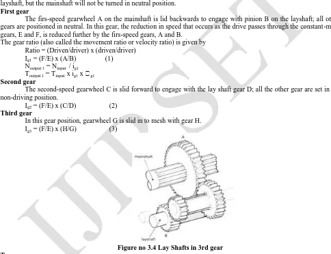
First gear
The firs-speed gearwheel A on the mainshaft is lid backwards to engage with pinion B on the layshaft; all other gears are positioned in neutral. In this gear, the reduction in speed that occurs as the drive passes through the constant-mesh gears, E and F, is reduced further by the firs-speed gears, A and B.
The gear ratio (also called the movement ratio or velocity ratio) is given by Ratio = (Driven/driver) x (driven/driver)
Ig1 = (F/E) x (A/B) (1)
Noutput 1 = Ninput / ig1
Toutput 1 = Tinput x ig1 x g1 Second gear
The second-speed gearwheel C is slid forward to engage with the lay shaft gear D; all the other gear are set in the non-driving position.
Ig2 = (F/E) x (C/D) (2) Third gear
In this gear position, gearwheel G is slid in to mesh with gear H. Ig3 = (F/E) x (H/G) (3)
Figure no 3.4 Lay Shafts in 3rd gear Top gear
DOI: 10.15680/IJIRSET.2014.0312117
Copyright to IJIRSET www.ijirset.com 18136 Reverse gear
Sliding a reverse gear between any two gears on the layshaft and main shaft is the method used to change the direction of rotation of the output shaft.
The simplest arrangement uses a single reverse gear, which is mounted on a short shaft. This shaft is positioned so that the reverse can slide and mesh with the two first-speed gears as shown in the figure. The gear ratio is
igr = (Driven/Driver) x (Driven/Driver) x (Driven/Driver)
= (F/E) x (J/B) x (A/J)
= (F/E) x (A/B) (4)
This is the same ratio as for first gear, and irrespectively of the size of gear J, it will be seen that the ratio always remains the same. For this reason it is called an idler – it changes the direction, but does not alter the ratio.
With the idler arrangement, some drivers persistently slip the clutch to maintain a low reversing speed. Excessive clutch wear resulting from this practice is minimized when the reverse ratio is set lower than first gear. This achieved by using a reverse gear arrangement as shown in the figure.
Instead of single idler, the compound reverse gear has two gear pinions joined together. The reverse shaft is positioned so that the reverse pinions are able to mesh simultaneously with the appropriate lay shaft and main shaft gears. Reverse gear mechanism arrangement use for various gear position and selecting mechanism in this method. This shaft is positioned so that the reverse can slide and mesh with the two first-speed gears.
Gear Changing
When one gear is moved to engage with another gear noise will result if the peripheral (outside) speeds are not the same to avoid this, the driver of the vehicle having a sliding-mesh gearbox performs an operation called double declutching.
Select mechanism
A fork of the type shown in figure is used to slide a gearwheel along the main shaft in order to select the appropriate gear. It is mounted on its own rod and links the driver‟s gear stick to the sliding gearbox. Every gearbox must be fitted with the following:
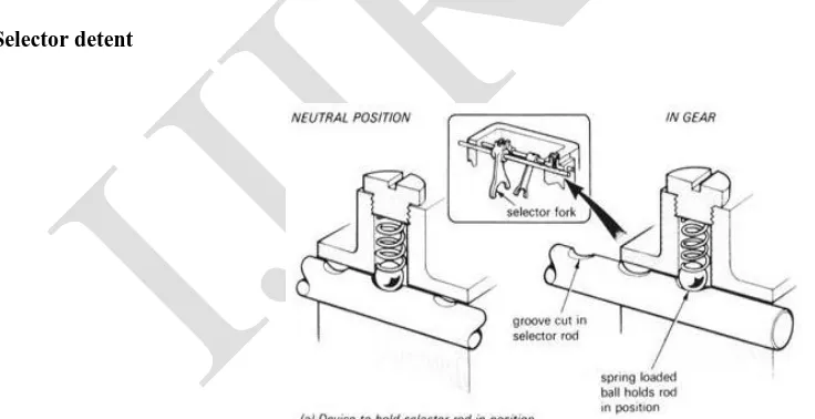
Selector detent
DOI: 10.15680/IJIRSET.2014.0312117
Copyright to IJIRSET www.ijirset.com 18137
Holds the gears and selectors in position and so prevent gear engagement or disengagement due to vibration. The figure shows a typical arrangement suitable for a layout having the selector fork locked to the rod.
Interlock mechanism
Prevents two gears engaging simultaneously; if this occurs the gearbox will lock up and shaft rotation will be impossible. Although the interlock device takes a number of different forms, the arrangement shown in the figure is one of the most common.
The interlock mechanism of used for driver change the gear center detent plug may be lose or even missing. To correct, inspect the various components of the gear shift mechanism and replace the defective parts.
Initial movement of the selector a sleeve carries the hub towards the gear and allows the cones adjusts the speed of the gearwheel to suit the hub and main shaft.
Figure no 3.6 Inter Lock Mechanism
DOI: 10.15680/IJIRSET.2014.0312117
Copyright to IJIRSET www.ijirset.com 18138
In addition to the mechanism use for driving a vehicle along a road, a power supply is often required for operating external items of auxiliary equipment.
A light truck having a tipping mechanism is one example, but the most varied application of power take-off units is associated with specialized off-road vehicles. The figure shows a typical power take-off arrangement that is driven from the gearbox lay shaft.
Disadvantages of the sliding mesh
Although the mechanical efficiency of the sliding mesh gearbox was high, it suffered from two great disadvantages:
1. Gear noise due to the type of gear.
2. The difficulty of obtaining a smooth, quit and quick change of gear without the great skill and judgment.
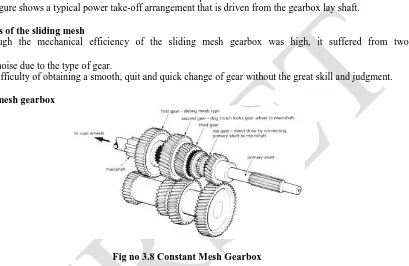
3.8 Constant-mesh gearbox
Fig no 3.8 Constant Mesh Gearbox
The main feature is the use of the stronger helical of double helical gears which lead to quieter operation. In this design, the main shaft pinions revolves freely on bushes or needle-roller bearings and are all in constant engagement with the corresponding lay shaft wheels. The gear operation is obtained by locking the respective gear to the main shaft by means of a dog clutch. The layout of the box is shown in the figure.
With this arrangement the quieter-running helical gears can be employed, and during gear changing the noise and wear are reduced by the simultaneous engagement of all the dogs instead of only a pair of gear teeth as on the sliding-mesh gearbox.
DOI: 10.15680/IJIRSET.2014.0312117
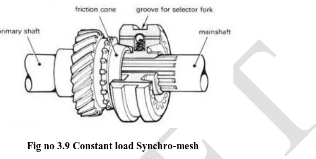
Copyright to IJIRSET www.ijirset.com 18139 3.9 Constant-load synchro-mesh
Fig no 3.9 Constant load Synchro-mesh
The figure shows unite main details of. Fundamentally the box is laid out in same manner as a constant-mesh, with the exception that a cone clutch is fitted between the dog and gear members. The initial movement of the selector a sleeve carries the hub towards the gear and allows the cones adjusts the speed of the gearwheel to suit the hub and main shaft
3. 10 Baulk ring synchro-mesh
This system is designed to overcome the main disadvantage of the earlier design- noise or crashing of the gears due to a quick change, by adding baulking ring to do the job as shown in the figure.
3. 11 Additional gear ratios
Commercial vehicles having a relatively low power/weight ratio, and operating under unloaded to fully loaded conditions, require additional gears for efficient operation. The main feature is the use of the stronger helical of double helical gears which lead to quieter operation. In this design, the main shaft pinions revolves freely on bushes or needle-roller bearings and are all in constant engagement with the corresponding lay shaft wheels.
IV . DC MOTOR
A DC motor is an electric motor that runs on direct current (DC) electricity. DC motors were used to run machinery, often eliminating the need for a local steam engine or internal combustion engine. DC motors can operate directly from rechargeable batteries, providing the motive power for the first electric vehicles. Today DC motors are still found in applications as small as toys and disk drives, or in large sizes to operate steel rolling mills and paper machines. Modern DC motors are nearly always operated in conjunction with power electronic devices.
Two important performance parameters of DC motors are the Motor constants, Kv and Km . Two types component motors i) Brush ii) Brushless
4.1 Type of DC motor
There are three types of connections used for DC electric motors: series, shunt and compound. These types of connections configure how the motor's field and armature windings are connected together. The type of connection is significant because it determines the characteristics of the motor and is selected for speed/torque requirements of the load.
DOI: 10.15680/IJIRSET.2014.0312117
Copyright to IJIRSET www.ijirset.com 18140 V. FEATURES OF 89c51 MICRO CONTROLLERS
1. Compatible with MCS-51TM Products Equivalent to 8051.
2. 4k Bytes of Reprogrammable Flash Memory (Endurance: 1000 write/Erase Cycles)
3. Maximum speed of operation: 24 MHZ Can be operated at a maximum frequency of 24 MHz 4. Three-level Program Memory lock Three levels of program memory lock for software security 5. 128X 8 – Bit internal RAM128 Bytes of RAM for temporary data storage
6. 32 programmable I\O Lines Four PORTS each having 8 lines, can be used as input or output 7. Two 16-Bit Timer/Counters2 Timer/counters for performing timing or counting operations
8. Six Interrupt Sources Two external interrupt for communicating with outside world & other Internal interrupts are for software communication
9. Programmable Serial Channel One serial communications channel for communicating with other Devices like computer etc.
10. Low power idle and Power down modes
5.1 Advantages of Micro-controller:
1. The number of discrete components required is less. 2. It is to program
3. Reliability is high
4. Easy to modify the program 5. Less complexity is hardware circuit
6. All MCUs have on-chip resources to achieve a higher level of integration and reliability at a lower cost
7. Built-in resources increase reliability because they do not require any External circuitry to be working for the resourced to function
8. They are pre-tested by the manufacturer and conserve board space by Integrating the circuitry in to the MCU. 9. Microprocessors is that these are general purpose electronic processing Devices which can be programmed to executed a number of tasks.
DOI: 10.15680/IJIRSET.2014.0312117
Copyright to IJIRSET www.ijirset.com 18141 VI.CLUTCH MASTER CYLINDER
The detailed construction of the master cylinder had been shown in figure. In engaged condition when the clutch fork in the released position, the push rod rests against its stop due to pedals return spring. Also the pressure of master cylinder spring keeps the plunger in its back position. The flange at the end of the valve shank contacts the spring retainer.
CLUTCH SLAVE CYLINDER
Further movement of the plunger displaces fluid through the pipeline to the slave cylinder and disengage the clutch. The construction of the slave cylinder is made clear by means of fig. The return spring in the slave cylinder maintains some pressure on the release fork so that the thrust bearing is always in contact with the release levers.
STEPPER MOTOR
Stepper motor is a machine, which converts electrical energy in to mechanically energy. The motor and the gear box unit is usually located in nearby (master cylinder) hydraulic circuit.
HANDY SWITCH
A handy switch is provides with the gear shift lever. And it is connected to the relay unit. The relay unit controls the motor.
6.2 Pictorial view of experimental setup
6.5 Specifications of project
Table No 5.1 Specifications of selected system
System Selected type
Clutch Single plate frictional
clutch
Gearbox Synchromesh gearbox
Clutching motor Half stepped DC motor
Input DC motor with step down
transformer
Control Relay circuit
DOI: 10.15680/IJIRSET.2014.0312117
Copyright to IJIRSET www.ijirset.com 18142 Characteristics of system selected Clutch:
Single plate frictional clutch.
Gearbox:
Synchromesh gearbox.
Clutching motor:
Half stepped DC motor, Capacity 12v dc, Power of motor 200watts, Speed 300rpm.
Transformer:
Step downtransformer 1230/12v ac
Input DC motor:
Capacity 12v dc Power of the motor 100watts Speed 600 rpm
Limit switch:
Limit switch – Normally closed.
Fabrication of clutching system
The following steps are followed for fabrication of clutching system 1. The design layout of the clutching system is to be done first. 2. Each system is selected based on the specification and need.
3. First, the clutch plate and clutch lever need to be modified to accommodate the motor and limit switch circuit. 4. The limit switch is then connected with the relay circuit which is programmed to control the motor.
5. The gearbox is now aligned with clutching system. 6. Now the entire system is assembled together.
Objective
1. To make clutching system easier. 2. To aid physically challenged person. 3. For smooth operation of clutch. 4. To reduce manpower.
5. Objective of the project is easy to change gear 6. Eliminate the clutch pedal
7. Understanding of electronic sensor system. 8. This project fix in all type of vehicles 9. This project is less cost.
DOI: 10.15680/IJIRSET.2014.0312117
Copyright to IJIRSET www.ijirset.com 18143 VII. WORKING PRINCIPLE
7.1 Disengagement of clutch
While the driver changing the gear, he has to switch on the handy to energies the relay. So that, the energized relay operates the motor. The motor which in turn pulls the lever attached to the pushrod of the master cylinder.
The fluid comes out from the master cylinder reaches the slave cylinder under certain pressure. The pressurized fluid pushed the slave cylinder pushrod which is connected with the clutch release fork lever. So, the disengagement of clutch takes place
While press the button microcontroller energized the transformer. So stepper motor moving the clockwise direction. Master cylinder moving the forward direction and also slave cylinder moving the forward movement. So this time disengagement of the clutch.
7.2 Engagement of clutch
After changing the gear the driver has to switch off the handy switch. So that the relay will change its polarity. Then the motor rotates in opposite direction. Mean while, clutch release fork releases by means of spring force.
The fluid return back Slave cylinder to Master Cylinder. So the engagement of takes place. Cylinder push rod to control the motor ON\OFF condition.
Changing the gear release the button movement, so slave cylinder and master cylinder return back to original position. So oil is return back to the cylinder. Stepper motor is rotate reverse direction of this condition.
7.3 Applications
Light duty vehicle likes Car ,Jeep, Van Heavy duty vehicles are Bus, Lorry, Trucks
7.4 Advantages
Simple in design
More effective
Smooth in operation
Required less manpower
Comfort driving
Easy maintenance
VIII.CONCLUSION
This project is an innovative concept. It is a new dimension in the transmission system of a car lots of inputs are also got from the car specialists and academicians for its improvements. The concept can be transformed to a real time fitment on further development.
By implementing our project in vehicles, it‟s very useful for physically unable persons. It will be very convenient for them to drive the vehicle and also ease to change the gears. By taking as a base, analyzing it, we can also control brake, accelerator by electronic means.
Using the 89c51 microcontroller we could make the relay circuit for first and reverse gear operation. And for other gears we could use speed control circuit. Here we could use stepper motor as the actuator which may get the signal from the microcontroller. Then the stepper motor may actuate the master cylinder and slave cylinder.
DOI: 10.15680/IJIRSET.2014.0312117
Copyright to IJIRSET www.ijirset.com 18144
day‟s 89c51 microcontroller used in various electronics conditions. This program also run the stepper motor is very smoothly.
APPENDIX Micro controller program:
; swatch
;--- ;date ;p1.2=1 switch not press,0=press ;put 41=55 if switch pressed ;p1.7= relay output
;30h =time count value org 0000h nop ajmp begin org 000bh ajmp int org 0050h
begin: mov sp,#60h mov tcon,#00h clr p1.7 mov ie,#00h mov p0,#00h mov p2,#00h mov 41h,#77h ; mov 30h,#00h mov th0,#06h mov psw,#00h mov r0,#04h mov r1,#0ah mov r2,#64h setb p1.2 setb p1.3 setb p1.4 setb p1.5 setb p1.6 mov tmod,#02h setb tcon.4 mov ie,#82h keyread: mov a,41h
cjne a,#77h,krdend setb p1.2 jb p1.2,krdend
DOI: 10.15680/IJIRSET.2014.0312117
Copyright to IJIRSET www.ijirset.com 18145
dly: push psw ;delay mov psw,#00h mov r6,#10h
dly1: djnz r6,dly1 ;r5 dly counter pop psw
ret org 0400h int: push psw push acc push dpl push dph mov psw,#00h djnz r0,in1 mov r0,#04h djnz r1,in1 mov r1,#0ah djnz r2,in1 mov r2,#64h ljmp intnest in1: ljmp intend intnest: mov a,41h cjne a,#55h,int2 setb p1.7 mov a,30h
cjne a,#02h,int3 ;calibration time =2 if you mov 41h,#77h ;want change it
int2: mov 30h,#00h clr p1.7 ljmp intend int3: setb p1.7 inc 30h intend: pop dph
pop dpl pop acc pop psw reti end
REFERENCES
1. p.m.heldt, “the automobile chassis”- the Clinton. 208-350.
2. Sundararajan M., "Optical instrument for correlative analysis of human ECG and breathing signal", International Journal of Biomedical Engineering
and Technology, ISSN : 0976 - 2965, 6(4) (2011) pp.350-362.
3. r.b.gupta “the automobile engineering” tech publications- new delhi.355-413.
4. Vijayaprakash S., Langeswaran K., Gowtham Kumar S., Revathy R., Balasubramanian M.P., "Nephro-protective significance of kaempferol on
mercuric chloride induced toxicity in Wistar albino rats", Biomedicine and Aging Pathology, ISSN : 2210-5220, 3(3) (2013) pp.119-124.
5. William crouse. “Auto mechanics”.711-906.
6. Sundar Raj M., Arkin V.H., Adalarasu, Jagannath M., "Nanocomposites based on polymer and hydroxyapatite for drug delivery application", Indian
Journal of Science and Technology, ISSN : 0974-6846, 6(S5) (2013) pp.4653-4658.
DOI: 10.15680/IJIRSET.2014.0312117
Copyright to IJIRSET www.ijirset.com 18146
8. Kumar S., Das M.P., Jeyanthi Rebecca L., Sharmila S., "Isolation and identification of LDPE degrading fungi from municipal solid waste", Journal
of Chemical and Pharmaceutical Research, ISSN : 0975 – 7384 5(3) (2013) pp.78-81.
9. Gianluca Lucente, Marcello Montanari, and carlo Rossi “modeling of an automated manual transmission system, Mechatronics vol.17.
10. Laljee R.P., Muddaiah S., Salagundi B., Cariappa P.M., Indra A.S., Sanjay V., Ramanathan A., "Interferon stimulated gene - ISG15 is a potential
diagnostic biomarker in oral squamous cell carcinomas", Asian Pacific Journal of Cancer Prevention, ISSN : 1513-7368, 14(2) (2013) pp.1147-1150.
11. Yu Zhisheng, “Automotive Theory,” Beijing china machine press, 2005
12. M. Taghizadesh, A.ghaffari, and F.Najafi “modeling and indentification of a solenodid valve for pwm control ap Hamilton, T. Technology Review, The Air car Preps for market.
13. Ariponnammal S. and Natarajan S. “Transport phenomena of Sm Se 1-x Pramana–journal of physics.
14. Jenkins G.m and Walts D.G , Spectral analysis and its application‟
15. k.s ray and D.D majumder” application of circle criteria for stabilityAnalysis of linear SISO and MIMO system associated with fuzzy logic Controller, Man and cybernetics, vol.14.
16. Pietro Dolcini, carlos canudas de wit, and Hubert Bechart lurch avoidance Stategy And its implementation in AMT vechiles vol.18
17. P Thamarai, B Karthik, Automatic Braking and Evasive Steering for Active Pedestrian Safety, Middle-East Journal of Scientific Research 20 (10),
PP 1271-1276, 2014.
18. M.Bharathi, Golden Kumar,Design Approach For Pitch Axis Stabilization of 3-Dof Helicopter System an LQR Controller,International Journal of
Advanced Research in Electrical, Electronics and Instrumentation Engineering,ISSN 2278 - 8875 , pp 351-365 ,Vol. 1, Issue 5, November 2012.
19. SRIDHAR RAJA. D ,Foliated UC-EBG UWB Bandpass filter ,International Journal of Advanced Research in Electrical, Electronics and
Instrumentation Engineering ,ISSN (Print) : 2320 – 3765,pp 3701-3708,Vol. 2, Issue 8, August 2013.
20. V.M. Ramaa Priyaa,Predictive Control in Power Converters,International Journal of Advanced Research in Electrical, Electronics and
Instrumentation Engineering, ISSN (Print) : 2320 – 3765 , pp 10475-10478 ,Vol. 3, Issue 7, July 2014.
21. Vijayan T ,Performance of Microstrip Directional Coupler Using Synthesis Technique,International Journal of Advanced Research in Electrical,
Electronics and Instrumentation Engineering, ISSN: 2278 – 8875, pp 761-767,Vol. 2, Issue 3, March 2013.
22. Vijayan T ,Performance Image Compression using Lifting based EEWITA,International Journal of Advanced Research in Electrical, Electronics and