OCTOBER, 2000
NEC America, Inc.
Hotel Office Data Specification
imply a Hotel Console. Most features described in this manual require a Hotel
Console. However, some features (including A-57, A-73, I-23, P-34, and V-16)
can also be performed using a Business Console.
Minimum firmware may be required. Contact NEC Engineering for additional
information.
NEC America, Inc. reserves the right to change the specifications, functions, or
features, at any time, without notice.
NEC America, Inc. has prepared this document for use by its employees and
customers. The information contained herein is the property of NEC America,
Inc. and shall not be reproduced without prior written approval from NEC
America, Inc.
NEAX
®and D
term®are registered trademarks of NEC Corporation.
Copyright 2000
ISSUE 1 ISSUE 2 ISSUE 3 ISSUE 4
DATE OCTOBER, 2000 DATE DATE DATE
ISSUE 5 ISSUE 6 ISSUE 7 ISSUE 8
DATE DATE DATE DATE
NEAX2400 IPX
Hotel Office Data Specification
Revision Sheet 1/4iii 1
iv 1
v 1
vi 1
1 1
2 1
3 1
4 1
5 1
6 1
7 1
8 1
9 1
10 1
11 1
12 1
13 1
14 1
15 1
16 1
17 1
18 1
19 1
20 1
21 1
22 1
23 1
24 1
25 1
26 1
27 1
28 1
29 1
30 1
31 1
32 1
35 1
36 1
37 1
38 1
39 1
40 1
41 1
42 1
43 1
44 1
45 1
46 1
47 1
48 1
49 1
50 1
51 1
52 1
53 1
54 1
55 1
56 1
57 1
58 1
59 1
60 1
61 1
62 1
63 1
64 1
65 1
66 1
67 1
68 1
69 1
ISSUE 1 ISSUE 2 ISSUE 3 ISSUE 4
DATE OCTOBER, 2000 DATE DATE DATE
ISSUE 5 ISSUE 6 ISSUE 7 ISSUE 8
DATE DATE DATE DATE
NEAX2400 IPX
Hotel Office Data Specification
Revision Sheet 2/474 1
75 1
76 1
77 1
78 1
79 1
80 1
81 1
82 1
83 1
84 1
85 1
86 1
87 1
88 1
89 1
90 1
91 1
92 1
93 1
94 1
95 1
96 1
97 1
98 1
99 1
100 1
101 1
102 1
103 1
104 1
105 1
106 1
107 1
108 1
112 1
113 1
114 1
115 1
116 1
117 1
118 1
119 1
120 1
121 1
122 1
123 1
124 1
125 1
126 1
127 1
128 1
129 1
130 1
131 1
132 1
133 1
134 1
135 1
136 1
137 1
138 1
139 1
140 1
141 1
142 1
143 1
144 1
145 1
ISSUE 1 ISSUE 2 ISSUE 3 ISSUE 4
DATE OCTOBER, 2000 DATE DATE DATE
ISSUE 5 ISSUE 6 ISSUE 7 ISSUE 8
DATE DATE DATE DATE
NEAX2400 IPX
Hotel Office Data Specification
Revision Sheet 3/4149 1
150 1
151 1
152 1
153 1
154 1
155 1
156 1
157 1
158 1
159 1
160 1
161 1
162 1
163 1
164 1
165 1
166 1
167 1
168 1
169 1
170 1
171 1
172 1
173 1
174 1
175 1
176 1
177 1
178 1
179 1
180 1
181 1
182 1
183 1
184 1
187 1
188 1
189 1
190 1
191 1
192 1
193 1
194 1
195 1
196 1
197 1
198 1
199 1
200 1
201 1
202 1
203 1
204 1
205 1
206 1
207 1
208 1
209 1
210 1
211 1
212 1
213 1
214 1
215 1
216 1
217 1
218 1
219 1
220 1
221 1
ISSUE 1 ISSUE 2 ISSUE 3 ISSUE 4
DATE OCTOBER, 2000 DATE DATE DATE
ISSUE 5 ISSUE 6 ISSUE 7 ISSUE 8
DATE DATE DATE DATE
NEAX2400 IPX
Hotel Office Data Specification
Revision Sheet 4/4226 1
227 1
228 1
229 1
230 1
231 1
232 1
233 1
234 1
235 1
236 1
237 1
238 1
239 1
240 1
241 1
242 1
243 1
244 1
245 1
246 1
247 1
248 1
249 1
250 1
251 1
252 1
253 1
254 1
255 1
NEAX2400 IPX
Hotel Office Data Specification
TABLE OF CONTENTS
Page
List of Figures . . . iii
List of Tables . . . iv
Hotel Command List in Alphanumeric Order . . . v
CHAPTER 1 INTRODUCTION . . . 1
1. General . . . 1
2. How to Follow This Manual . . . 1
3. Reference Manuals . . . 1
CHAPTER 2 ASSIGNMENT . . . 3
1. General . . . 3
2. Getting Started-Hardware . . . 3
2.1 PC Specifications . . . 3
2.2 IPX MAT and IPX Connection . . . 4
2.3 Serial/Dialup Connection to IPX . . . 5
3. TCP/IP Considerations . . . 6
4. Installing IPX MAT Software . . . 7
5. IPX MAT Commands . . . 15
6. Configuring IPX MAT . . . 15
6.1 Serial/Direct Connection . . . 16
6.2 TCP/IP Connection . . . 18
6.2.1 Modifying or Adding a PBX Alias . . . 18
6.2.2 Assigning Network Information in Windows . . . 19
6.2.3 Starting the PBX System . . . 19
6.2.4 Logging in to IPX . . . 20
6.2.5 Assigning System Data . . . . 20
6.2.6 IPX MAT File Operations . . . 22
7. Data Assignment Flow Chart . . . 26
7.1 Local Node/Stand Alone . . . 26
CHAPTER 3 OFFICE DATA DESIGN SHEET . . . 31
1. Trunking Diagram . . . 31
2. Bay Face Layout . . . 31
3. Port Location Table . . . 31
4. Numbering Plan Table . . . 31
5. Restriction Tables . . . 31
AANP . . . 91
AGNP . . . 94
AGNPL . . . . . . 96
AGNPN . . . . . . 99
AASP . . . 101
AGSP . . . 129
AGSPL . . . 155
AGSPN . . . . . . 180
ASPS . . . 205
ASCR . . . 231
ATCR . . . 233
ADNR . . . 235
AAST . . . 237
AGST . . . 240
AASN . . . 243
AACL . . . 244
AGSN . . . 246
AGCL . . . 247
AHSU . . . 249
ADSS . . . 253
Figure 2-2 Serial/Dialup Connection to IPX. . . 5
Figure 2-3 TCP/IP Connection to Dual CPR of IPX. . . . 5
Figure 2-4 TCP/IP Connection (IP Address over the External LAN) . . . 6
Figure 2-5 IPX MAT Welcome Screen . . . 7
Figure 2-6 IPX MAT User Information Dialog . . . 8
Figure 2-7 Choose Location Destination Screen. . . 8
Figure 2-8 Winsock 2 Setup Message Dialog Box . . . 9
Figure 2-9 IPX MAT Installation Screen . . . 9
Figure 2-10 IPX MAT Setup Complete Dialog. . . 10
Figure 2-11 IPX MAT Installing Winsock2 Message Box . . . 11
Figure 2-12 Winsock2 Setup Message Dialog Box . . . . 11
Figure 2-13 DAO Welcome Screen . . . 11
Figure 2-14 DAO Select Components Screen. . . 12
Figure 2-15 Select Components Screen . . . 12
Figure 2-16 DAO Setup Screen. . . 13
Figure 2-17 DAO Information Message . . . 13
Figure 2-18 IPX MAT Main Menu . . . 14
Figure 2-19 IPX MAT Tool Bar . . . 14
Figure 2-20 PBX Administration . . . 17
Figure 2-21 Local Node/Stand Alone Data Flow Assignment Flow Chart (1/2). . . 26
Figure 2-22 Network Control Node Data Assignment Flow Chart (1/2). . . 28
Figure 2-23 Hotel Command Data Assignment Flow Chart (1/2) . . . 30
Figure 3-1 Trunking Diagram. . . 32
Figure 3-2 Card Mounting Slot . . . 34
Figure 3-3 Card Mounting Slot for 4-IMG System (1/4). . . 35
Figure 3-4 Card Mounting Slot for IPX-U System (1/5) . . . 39
Table 2-2 IPX MAT Commands . . . 15
Table 2-3 PBX Administration Default Values . . . 16
Table 3-1 Circuit Card Function Name. . . 33
Table 3-2 Service Feature Restriction Class . . . 46
AACL Assignment of Administration Station Class 244
AANP Assignment of Administration Numbering Plan 91
AASN Assignment of Alternated Administration Station Number 243
AASP Assignment of Administration Special Access Code 101
AAST Assignment of Administration Station Data 237
ADNR Assignment of Day/Night Restriction 235
ADSS Assignment of Direct Station Select 253
AGCL Assignment of Guest Station Class 247
AGNP Assignment of Guest Numbering Plan 94
AGNPL Assignment of Guest Numbering Plan for LDM 96
AGNPN Assignment of Guest Numbering Plan for NDM 99
AGSN Assignment of Alternated Guest Station Number 246
AGSP Assignment of Guest Special Access Code 129
AGSPL Assignment of Guest Special Access Code for LDM 155
AGSPN Assignment of Guest Special Access Code for NDM 180
AGST Assignment of Guest Station Data 240
AHSU Assignment of Suite Room Station Number 249
AHSY Assignment of Hotel System Parameter 52
ASCR Assignment of Station Connection Restriction 231
ASPF Assignment of Special Access Code Floor 255
ASPS Assignment of Special Access Code for Split Access 205
This manual describes how to operate the Maintenance Administration Terminal (MAT) and plan the office
data. It also contains descriptions of the parameters for the NEAX2400 IPX.
2. How to Follow This Manual
The contents of this manual are:
•
CHAPTER 1
INTRODUCTION
This chapter explains how to use this manual.
•
CHAPTER 2
ASSIGNMENT
This chapter explains the system configuration and system specifications required to install and run the
MAT. It contains installation instructions and information about accelerator keys and navigation keys used
by MAT.
•
CHAPTER 3
OFFICE DATA DESIGN SHEET
This chapter contains the office design sheets used to design the configuration and specification of IPX.
•
CHAPTER 4
HOTEL SYSTEM COMMAND DESCRIPTIONS AND DATA SHEETS
This chapter explains the Hotel system command parameters of the NEAX2400 IPX.
3. Reference Manuals
When installing MAT and assigning the relevant system data, refer to the following manuals in addition to this
manual:
•
Feature Programming Manual
•
Fusion Network System Manual
•
Office Data Specification (for Business system commands)
Note:
The NEAX2400 IPX Office Data Specification for Business systems contains Hotel system-related
command information in the following sections:
• AAED
• AKYD
• ASPA
• AAKP
• ALRNN
• ASPAL
• AASP
• ANPN
• ASPAN
• AAST
• ARTD
• ASYD
• AGST
• ARTDN
• ATIM
1. General
This chapter describes the information needed to install and operate the Maintenance Administration Terminal
(MAT) software.
The IPX MAT software has the following functions:
•
Allows user-friendly Graphical User Interface (GUI) with Microsoft Windows 95/NT.
•
Provides both an Ethernet interface and a RS232C interface.
•
Allows access to a node within the Fusion Link network using a simple Login operation,
•
Supports remote maintenance capabilities through a dialup connection.
•
Dumps the PBX data into a data file using of the LIST UP command.
Note:
The recorded log file is a simple text file that can be printed or edited using any Windows application that
supports text file editing.
Since the IPX MAT runs on Microsoft’s 32 bit Windows plug-and-play operating system, peripheral hardware
(network, remote access, modems, printers, etc.) is easy to configure. IPX MAT does not require a dedicated
printer. Any printer supported by the operating system, including shared LAN printers, can be used.
2. Getting Started-Hardware
The IPX MAT PC should conform to the specifications explained in this section. The cables, modems, and
HUBs required depend on the connection type.
The IPX MAT allows you to access IPX using the following connection types:
•
Serial/direct
•
Serial/dialup
•
TCP/IP
2.1 PC Specifications
The IPX MAT software requires a PC with the following minimum specifications:
Table 2-1 PC Requirements to Run IPX MAT
CPU TYPE Pentium 166 or higher
Memory 32 MB or more for WIN 95 and NT
Hard Disk 500 MB of free space
Video Card and Monitor Any Microsoft Windows compatible video card (256 colors or more, screen size 800 X 600 resolution
2.2 IPX MAT and IPX Connection
Figure 2-1
shows a serial/direct connection to the IOC card of IPX. The serial/direct connection allows you
to access the IPX and the different nodes via the Fusion Link.
Figure 2-1 Serial/Direct Connection to IPX
IPX MAT software supports serial/direct connection to the target IPX. As seen in
Figure 2-2
, a modem is
required at both the remote maintenance center and the IPX site. The LINE port of the modem located at
the IPX site should be connected to the dedicated Line Circuit (LC), and the DATA port should be directly
connected to the IOC card. The serial/dialup connection allows you to access both the first node (IPX) of
the Fusion Link network and all other nodes within the Fusion Link network.
Network Any 10 BASE-T Network Interface Card when IPX MAT is connected across TCP/IP Communication Port COM1-COM4 when IPX MAT is connected across serial RS-232C port.
Mouse Any Microsoft compatible mouse.
Operating System Microsoft Windows 95 or Microsoft Windows NT Be sure to set “small fonts” in the property of the screen.
FUSION LINK
IPX
IPX NEAX 2400 TTY CABLE 1
IPX MAT IPX MAT PRINTER
Figure 2-2 Serial/Dialup Connection to IPX
The IPX MAT software provides an advanced communication software for IPX. IPX is maintained via the
LAN, WAN, or TCP/IP network on which it is running.
Figure 2-3
shows the simple configuration of the
TCP/IP connection. Using this connection, any node within the Fusion Link network can be accessed from
IPX MAT.
Figure 2-3 TCP/IP Connection to Dual CPR of IPX
FUSION LINK
IPX
IPX IPX MAT IPX MAT PRINTER
IOC
NEAX2400 TTY CABLE 3 68PH S 2 PORTS CA - A LC
TRK
MODEM MODEM
TELECOMMUNICATION NETWORK
FUSION LINK 10 BASE -T straight cable
HUB
IPX MAT IPX MAT PRINTER
LANI LANI
IPX
traffic.
Figure 2-4 TCP/IP Connection (IP Address over the External LAN)
3. TCP/IP Considerations
The IPX MAT can communicate with the IPX via an Ethernet TCP/IP connection. In order for the IPX MAT to
communicate via TCP/IP, the PC must have its network software, including the TCP/IP drivers, installed and in
operation prior to installing the IPX MAT software.
SERVER PC
LAN MAT
HUB MAT PRINTER
10BASE-T straight cable
2 setup has failed displays during the IPX MAT installation. This message is an expected response since the IPX
MAT installation program attempts to upgrade the TCP/IP WINSOCK drivers to the latest version. If these
drivers are not already installed, the upgrade process fails. The failure does not affect the successful installation
and operation of the IPX MAT, but the TCP/IP interface cannot be used.
It is always best to install the IPX MAT software after all network software is installed. Although it is not
recommended, it is possible to install the PC’s standard network software after the IPX MAT software has been
installed. If the IPX MAT software is installed prior to installing the network software, it will be necessary to
run the WINSOCK setup program from the IPX MAT CD after installing the network software.
To run the WINSOCK setup program:
1.
Insert the IPX MAT CD into the CD-ROM drive.
2.
The IPX MAT setup program starts automatically.
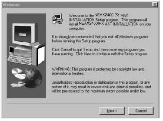
3.
Terminate (Cancel) the IPX MAT setup program on the Welcome Screen.
Figure 2-5 IPX MAT Welcome Screen
4.
Select the appropriate CD-ROM drive in Windows Explorer.
5.
Double-click the file named WS2SETUP.EXE.
For more information about configuring TCP/IP connections, see
Section 6.2, TCP/IP Connection
.
4. Installing IPX MAT Software
The following provides step-by-step instructions for installing the IPX MAT software for Windows 95/NT onto
your hard disk.
1.
Terminate all applications, prior to starting the installation process.
2.
Insert the CD-ROM into the CD-ROM drive. (The IPX MAT installation program starts automatically.)
NEAX2400IPX
Figure 2-6 IPX MAT User Information Dialog
4.
Click
Next
on the Choose Destination Location dialog box to install the IPX MAT software in the default
directory.
Note:
If you wish to install the software in another directory, you can click Browse to display a dialog box that
allows you to select or create another directory.
Figure 2-8 Winsock 2 Setup Message Dialog Box
6.
File copy starts automatically, while the displayed dialog boxes (See
Figure 2-9
) show the on-going
situation.
Figure 2-9 IPX MAT Installation Screen
7.
If the Setup Complete dialog box appears on the screen, the file copies have finished successfully. Click
Finish
to complete the IPX MAT software installation and restart your computer.
IPXMAT
IPXMAT Installation
Note:
If you are installing IPX MAT on an NT 4.0 workstation, the Winsock2 Setup message box does not display.
NT 4.0 does not require Winsock2 in order to run.
Figure 2-11 IPX MAT Installing Winsock2 Message Box
9.
After Winsock2 is installed, the Winsock2 Setup dialog box displays. This is an informational message
only. Click
OK
to continue installing the Data Access Objects (DAO) required to run IPX MAT.
Figure 2-12 Winsock2 Setup Message Dialog Box
10. Click
OK
. The DAO Welcome Screen displays.
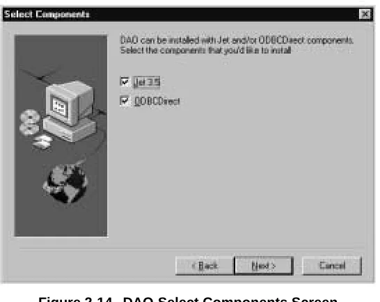
Figure 2-13 DAO Welcome Screen NEAX2400IPX
Figure 2-14 DAO Select Components Screen
12. Uncheck the ODBCDirect box and click
Next
. The Select Components dialog box displays.
Note:
If you do not uncheck the ODBCDirect box, error messages display once the DAO Setup program
completes. IPX MAT will run properly even though these messages display.
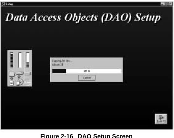
Figure 2-16 DAO Setup Screen
14. After the DAO files are installed, the DAO Information message box displays. Click
OK
. The IPX MAT
Installation screen displays.
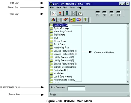
Figure 2-18 IPX MAT Main Menu
16. To configure the PBX Alias, use the instructions in
Section 6.2, TCP/IP Connection
.
Note:
Once you have configured the IPX MAT, you can use the Run Command line to enter task commands, or
you can select the command from the Command Folders. You can also perform IPX MAT tasks using either
the menu items, or the icons equivalent to the menu items.
Figure 2-19 IPX MAT Tool Bar
Command Folders Tool Bar
Title Bar
Enter commands here Status Bar Menu Bar
Collect New Traffic
Scan New Alarms/Traffic
Collect New Alarms Abort Data Collection
View Scanning Log
Processes About
Log On
Configure Log Out
The IPX MAT’s operation is very similar to that of the NEAX2400 MS-DOS MAT, so you will find that many
of the key stroke operations have been carried over into IPX MAT. In addition, some standard MS Windows
operations and key strokes are used. Use the following keys, or in some instances the mouse, to select or enter
data.
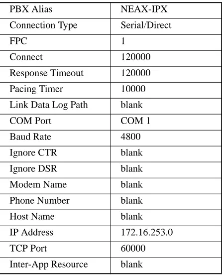
6. Configuring IPX MAT
This section explains the PBX Alias parameters you may configure using the PBX Administration dialog
window. It also lists the default values of NEAX-IPX, the default PBX Alias delivered with the IPX MAT
software. Prior to running the IPX MAT, you should either define a new PBX Alias, configure the default PBX
to work with your system, or plan to use the NEAX-IPX default Alias. NEAX-IPX is ready for use once the IPX
MAT software has been successfully installed.
Table 2-3
lists the default values displayed in the PBX
Administration dialog box when you select NEAX-IPX as your PBX Alias.
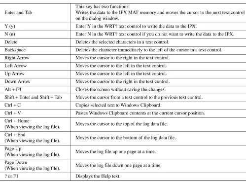
Table 2-2 IPX MAT Commands
Enter and Tab
This key has two functions:
Writes the data to the IPX MAT memory and moves the cursor to the next text control on the dialog window.
Y (y) Enter Y in the WRT? text control to write the data to the IPX.
N (n) Enter N in the WRT? text control if you do not want to write the data to the IPX. Delete Deletes the selected characters in a text control.
Backspace Deletes the character immediately to the left of the cursor in a text control. Right Arrow Moves the cursor to the right in the text control.
Left Arrow Moves the cursor to the left in the text control. Up Arrow Moves the cursor to the left in the text control. Down Arrow Moves the cursor to the right in the text control. Alt + F4 Closes the screen without saving the changes.
Shift + Enter and Shift + Tab Moves the cursor from a text control to the previous text control. Ctrl + C Copies selected text to Windows Clipboard.
Ctrl + V Pastes Windows Clipboard contents at the current cursor position. Ctrl + Home
(When viewing the log file). Moves the cursor to the top of the log data file. Ctrl + End
(When viewing the log file). Moves the cursor to the bottom of the log data file. Page Up
(When viewing the log file). Moves the log file up one page at a time. Page Down
(When viewing the log file). Moves the log file down one page at a time.
6.1 Serial/Direct Connection
The following steps explain how to configure the PBX Alias for a serial/direct connection using the
recommended default data.
Note 1:
The PBX Alias cannot have spaces in the name.
Note 2:
You can use other data when configuring IPX MAT. However, it is recommended that you use the default
data as previously described when configuring a new PBX Alias.
PBX Alias NEAX-IPX
Connection Type Serial/Direct
FPC 1
Connect 120000
Response Timeout 120000
Pacing Timer 10000
Link Data Log Path blank
COM Port COM 1
Baud Rate 4800
Ignore CTR blank
Ignore DSR blank
Modem Name blank
Phone Number blank
Host Name blank
IP Address 172.16.253.0
TCP Port 60000
Figure 2-20 PBX Administration
2. Enter a name for the PBX Alias in the PBX Alias box.
Note:
You can also define a PBX Alias by selecting the default NEXT-IPX or by modifying any other previously
defined Alias from the list in the PBX Alias box. If you select a PBX Alias from the list, its related
information displays in the additional fields on this dialog box. You can enter information in the Connect
Timeout, Response Timeout, Pacing Timer, and Link Data Log Path fields if necessary. However, the IPX
MAT software will run without changing the default data.
3. Select Serial/Direct as the Connection Type.
4. Enter the appropriate FPC (Fusion Link Point Code). 1 is the default value and should be used initially
for all new IPX systems. In a Fusion Network, this setting must match the FPC value entered into
Sys-tem Data SYS 1 INDEX 512.
5. Enter 120000 in the Connection Timeout text box.
6. Enter 120000 in the Response Timeout text box.
7. Enter 10000 in the Pacing Timer text box.
8. Clear (Remove) any text from the Link Data Log Path text control.
9. Set COM1 Baud rate to 4800. This is the default PBX value on the initial power up.
10. Leave the Host Name text box blank.
11. Leave the IP Address text box blank.
12. Leave the IP Port text box blank.
15. Click
Close
.
Note:
The PBX Administration dialog box changes adapting to EX-FCCS Network. Enter the Fusion Group
Number (FUG) which the PBX to be logged-in belongs. “Connection Timeout”, “Response Timeout”, and
“Pacing Timer” text box is not provided. Others are the same as previous one. The PBX dialog box is as
shown below.
6.2 TCP/IP Connection
This section explains how to add or modify a PBX Alias in IPX MAT when it is connected to a PBX using
a TCP/IP connection through a Local Area Network (LAN).
Procedure Overview
1. Modify or add a PBX Alias.
2. Assign the network information in Windows.
3. Start the PBX system.
4. Log in to IPX MAT.
5. Assign the system data.
6. Set up the IPX MAT file operations for logging purposes.
Note:
If your IPX is to reside on your existing LAN, you will need to obtain an available IP address from your
System Administrator before you configure the PBX Alias.
6.2.1 Modifying or Adding a PBX Alias
Note:
The PBX Alias cannot have spaces in its name.
PBX Administration
Add
Add
Modify
Modify
Clear
Close
PBX Alias Connection Type
FUG
COM Port Baud Rate
Modem Name Phone Number
Host Name IP Address TCP Port
TCP/IP Settings Serial Settings
TCP/IP
bsc7200 10.41.207.207 60000
3
FPC
1 Delete
1. From the PBX menu, select Configuration to open the PBX Administration dialog box.
2. Enter a name for the PBX Alias in the PBX Alias box.
Note:
You can also define a PBX Alias by selecting the default NEXT-PBX or by modifying any other previously
defined Alias from the list in the PBX Alias box. If you select a PBX Alias from the list, its related
information displays in the additional fields on this dialog box. You can enter information in the Connect
Timeout, Response Timeout, Pacing Timer, and Link Data Log Path fields if necessary.
3. Select TCP/IP as the Connection Type.
4. Enter the appropriate FPC (Fusion Link Point Code). 1 is the default value and should be used
initially for all new IPX systems. In a Fusion Network, this setting must follow the FPC value
entered into System Data SYS 1 INDEX 512.
5. Enter 120000 in the Connection Timeout text box.
6. Enter 120000 in the Response Timeout text box.
7. Enter 10000 in the Pacing Timer text box.
8. Leave the Link Data Log Path text box blank.
9. Enter the name of the host your system is using in the Host Name text box.
10. Enter 172.16.253.0 in the IP Address text box, or enter the IP Address supplied by your network
administrator.
11. Enter 60000 in the IP Port text box.
12. Leave the Inter-App Resource text box blank.
13. Click
Add
to write the data.
14. Click
Close
.
15. Exit IPX MAT.
6.2.2 Assigning Network Information in Windows
Before you can run the IPX MAT software, you have to configure your network information in the
Windows operating system. For information on configuring network information, see the Network Circuit
Card Installation Manual or talk to your network administrator. After configuring the network information,
you must restart the PC before you can log in to the IPX via the IPX MAT TCP/IP connection.
6.2.3 Starting the PBX System
runs properly.
6.2.4 Logging in to IPX
After you have defined the PBX Alias in IPX MAT and the TCP/IP network connection in Windows,
you are ready to Log in to IPX. The Login operation allows you to select the target IPX (node) with
which you are attempting to communicate. Once you log in to IPX, you may assign or delete office data,
monitor the status of IPX, obtain System Messages through the IPX’s self-diagnosis function, and
mon-itor the IPX traffic and Peg count data. Once you have completed the tasks you intended to perform, you
should log out to prevent accidental changes to the data. The following steps explain how to log in to
IPX.
Note:
The maximum number of concurrent connections for the IPX is four.
1. From the IPX menu, select Log In.
2. Select the PBX you want to connect to by choosing the appropriate PBX Alias from the PBX Alias
box.
Note:
When the User ID data is programmed in AUIDN command after the required office data assignment, enter
the proper user name and password to login to the NCN.
3. Click
Login
.
4. A successful log in displays the successful Login message box.
Note:
If the Login message box does not display, the login process has failed. If the login process fails, you should
reopen the PBX Configuration dialog box and verify the PBX Alias configuration information. If the PBX
Alias has been correctly configured, you should then test the physical connections to the PBX.
5. Click
OK
on the Login message box.
6.2.5 Assigning System Data
This section explains how to assign the IP Address and the SubNet Mask using the default IP Address
172.16.253.0 and the default SubNet Mask 00.00.00.00. Both fields must be entered using their
hexadecimal equivalents.
Note:
You may find it convenient to use the Calculator in the Windows Accessories to find the hexadecimal
equivalent of the IP Address and the SubNet Mask. To convert from decimal to hexadecimal:
1. Select Calculator from the Accessories menu.
2. From the View menu, select Scientific.
3. Verify that Dec is selected.
4. Click the first three numbers of the IP Address on the Calculator key pad.
5. Select Hex.
and repeat the previous steps.
1. Type ASYDL in the Run Command text box.
2. Press Enter.
3. Type 1 in the SYS text box and press Enter.
4. Type 513 in the INDEX text box and press Enter.
5. Type 01H in the DATA text box and press Enter.
6. Type Y in the WRT? text box and press Enter.
7. Type 1 in the SYS text box and press Enter.
8. Type 514 in the INDEX text box and press Enter.
9. Type 01H in the DATA text box and press Enter.
10. Type Y in the WRT? text box and press Enter.
Note:
The following steps explain how to assign the default IP Address.
11. Type 1 in the SYS text box and press Enter.
12. Type 515 in the INDEX text box and press Enter.
13. Type AC (hexadecimal equivalent of 172) in the DATA text box and press Enter.
14. Type Y in the WRT? text box and press Enter.
15. Type 1 in the SYS text box and press Enter.
16. Type 516 in the INDEX text box and press Enter.
17. Type 10 (hexadecimal equivalent of 16) in the DATA text box and press Enter.
18. Type Y in the WRT? text box and press Enter.
19. Type 1 in the SYS text box and press Enter.
20. Type 517 in the INDEX text box and press Enter.
21. Type FD (hexadecimal equivalent of 253) in the DATA text box and press Enter.
22. Type Y in the WRT? text box and press Enter.
23. Type 1 in the SYS text box and press Enter.
24. Type 518 in the INDEX text box and press Enter.
Note:
The following steps explain how to assign the default SubNet Mask.
27. Type 1 in the SYS text box and press Enter.
28. Type 519 in the INDEX text box and press Enter.
29. Type FF in the DATA text box and press Enter.
30. Type Y in the WRT? text box and press Enter.
31. Type 1 in the SYS text box and press Enter.
32. Type 520 in the INDEX text box and press Enter.
33. Type FF in the DATA text box and press Enter.
34. Type Y in the WRT? text box and press Enter.
35. Type 1 in the SYS text box and press Enter.
36. Type 521 in the INDEX text box and press Enter.
37. Type 00 in the DATA text box and press Enter.
38. Type Y in the WRT? text box and press Enter.
39. Type 1 in the SYS text box and press Enter.
40. Type 522 in the INDEX text box and press Enter.
41. Type 00 in the DATA text box and press Enter.
42. Type Y in the WRT? text box and press Enter.
6.2.6 IPX MAT File Operations
The IPX MAT creates three types of files; Command Log files, Office Data Backup files, and List-up
Command Report data tables. Command Log files and List-up Command Report data tables are the only
files a user needs to view. The Office Data Backup files are used strictly for saving and storing the PBX
Office Data.
6.2.6.1 Office Data Backup
standard operating functions to copy the saved data to floppy disks, zip drive disks, writable CD-ROM
drives, or any other type of external storage devices supported by the operating system. Doing a three
phase backup (save) ensures the IPX Office data is safe and always available for restoration in case of
an IPX data memory loss, hard disk failure, or any other IPX-related catastrophic failure that requires
data memory to be reloaded.
MEM_HDD and HDD_MAT are the two commands used for this three-phase backup. Once the data is
saved to the IPX MAT, you can use Explorer to copy the appropriate files to the external mass storage
device. To use Explorer, you must first determine where the IPX MAT copy of the numerous IPX Office
Data backup files resides.
As an example, assume the default drive and directory C:\IPXMAT were used when IPX MAT was
installed. Also assume that a PBX Alias was configured using the PBX Configuration dialog and
assigned the PBX Alias name MY_PBX.
The IPX MAT always uses the same data directory structure when backing up data from the IPX. It
cre-ates a sub-directory under the IPX MAT home directory called DATA. Under the DATA directory
an-other sub-directory using the PBX Alias name is created. In our example, this sub-directory is named
MY_PBX. Under the PBX Alias directory, another sub-directory is created. The name of this directory
is BACKUP. This directory structure always holds true. The only variables are the name of the IPX MAT
home directory (default C:\IPXMAT) and the PBX Alias directory (in our example, MY_PBX). The
complete directory structure for our example is as follows: C:\IPXMAT\DATA\MY_PBX\BACKUP.
The bottom sub-directory (BACKUP) contains all files that have been backed up from the IPX using the
HDD_MAT command.
To save these files to an external storage device, open Explorer, navigate to the appropriate backup
directory (C:\IPXMAT\DATA\MY_PBX\BACKUP) and select ALL files and/or sub-directories and
copy them to your external device. You now have a safe backup of your IPX data memory that can be
stored at an offsite location.
6.2.6.2 MEM_HDD
The following steps explain how to perform the backup and restore of PBX data to the PBX hard drive.
1. Enter MEM_HDD in the Run Command field on the IPX MAT main menu.
2. Press Enter.
3. The Backup and Restore dialog box displays.
4. Select Memory to Hard Disk in the Direction Select list.
5. Select Data Memory in the Data Type Selection list.
6. Select Auto Verify if you want to verify the data. This is an optional step.
Action/Information, Direction, Data Type, and Time Stamp. The Action/Information column shows the
Action being taken (saving or restoring), or the Information being saved. The Direction column shows
where the data is being saved or restored (in this case, memory to PBX Hard Disk). The Data Type
column shows the type of data you selected in the Data Type Selection list. The Time Stamp column
shows the day, month, year, hour, minute, and second the data was backed up or restored.
6.2.6.3 HDD_MAT
The following steps explain how to backup and restore PBX data to the IPX MAT hard disk.
1. Enter HDD_MAT in the Run Command field on the IPX MAT main menu.
2. Press Enter.
3. The Backup and Restore dialog box displays.
4. Select PBX Hard Disk to MAT in the Direction Select list.
5. Select Data Memory in the Data Type Selection list.
6. Select Auto Verify if you want to verify the data. This is an optional step.
7. Click
Start
.
Once you have made the appropriate selections and clicked Start, you can scroll down and view the data
being saved in the Processing Status Log window. This section of the window is divided into the sections
Action/Information, Direction, Data Type, and Time Stamp. The Action/Information column shows the
Action being taken (saving or restoring), or the Information being saved. The Direction column shows
where the data is being saved or restored (in this case PBX Hard Disk to IPX MAT). The Data Type
column shows the type of data you selected in the Data Type Selection list. The Time Stamp column
shows the day, month, year, hour, minute, and second the data was backed up or restored.
6.2.6.4 List-up Command Report Data Tables
These data files are tables assembled into an MS-Access Database format. The List-up commands create
the database and tables, populating them based on the information specified by the user. After the
database and tables are created, the report that automatically finds the correct data table and presents the
stored data in a format suitable for viewing is launched. These data tables are cleared and repopulated
each time the corresponding List-up command is run. These data tables require no user intervention.
6.2.6.5 Command Log Files
continues to grow as each command is run and interactions with the IPX PBX are transacted. It doesn’t
matter whether the operation is a query, a change, a create, or a delete, the operation, its data, and its
status will always be logged (added to this log file).
The log file can be viewed any time by selecting it from the command’s view menu selection. Once the
log file viewing window is opened, the log file can be printed by selecting the print option from its File
menu selection. Pressing the CTRL+END key combination will quickly take you to the end of the file
where the latest changes have been appended.
Since the log file continually grows, you should regularly delete this file to conserve disk space. It also
makes the file much more manageable and useful if it is not full of log entries that are no longer of
interest. To delete and otherwise manage this file, the IPX MAT main menu contains menu selections
that will present a log file maintenance dialog. From here, the log file can be easily deleted.
6.2.6.6 Viewing the Log Data File
To view the log data file:
1. Display the Backup and Restore dialog box.
2. Select Operation Log from the View menu.
3. The log file FileViewer window displays.
6.2.6.7 Printing the Log Data File
To print the log data file:
1. Display the log file in the FileViewer window.
2. Select Print from the File menu.
6.2.6.8 Copying Data from the Log File
To copy data from the log file:
1. Display the log file in the FileViewer window.
2. Highlight the data you want to copy.
3. Select Copy from the Edit menu.
6.2.6.9 Pasting Log File Data
To paste log file data into another text editing tool:
1. Open the text editing tool you want to paste the data into.
2. Select paste from the Edit menu.
This section shows the data assignment flow chart for IPX. The standard data assignment is illustrated on the
following flow charts.
•
Local Node/Stand Alone
•
Network Control Node
•
Hotel Command
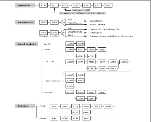
7.1 Local Node/Stand Alone
The following flow chart shows the data assignment for MAT when operated in a Local Node/Stand Alone
environment.
1. Local Node/Stand Alone
Figure 2-21 Local Node/Stand Alone Data Flow Assignment Flow Chart (1/2) ATIM
System Base ASYD ASYDL AUNT AIOC ASTD AOFC
AMND ARNP
ANND ASTP AOSP ARNP
ACMO ATCP AFRS AOPR AADC
AFRSL AOPRL AADCL
ASDC
AMND ARNP
AUNE AMND
ARSC ARRC ATDP AARP APCR AEFR
ATDPL AARPL
ASFC ACFR ATNR AABD
ANPD ASPA
ANPDL ASPAL
SRV
SRV
STN
SSC/SSCA, etc.
SSC
TELN
Sys1 Index 512 - 1535
Sys1 Index 0 - 511 , Sys2 Index 0 - 15 & Sys3 Index 0 - 31
Station Number
Service / Network
Telephone Number available in the Self node only
Timing Start is available
Numbering Plan
Network Numbering
Restriction
2nd DT :
Sender
LCR / LCRS :
Uniform Numbering :
AUNEL
ALDN ASTP AISP ARAC
Incoming :
Trunk:
Service:
:
Operator Call / OGQ / Priority Call OGC(A)/LCR(S) Outgoing Call
ASTPL AOSPL
Figure 2-21 Local Node/Stand Alone Data Assignment Flow Chart (2/2)
Trunk ATRK MBTK AMAT ASAT ATGL AAKP
ATRK MBTK
Service
CCIS No. 7
ISDN
ASHP ASHC ASHU AUCD AUOG AUAD ACPG ACPE
AISA AISD ASGD ASID ACFS ASLU1 ASLU2
ACSA ACSI ANCD ATAS AEKD AAND AANDE
ASPD AATC ACFO
ARPC ARDN
ACDD ACNP ACND AFCP ACBC AVTC AVTL
ATT :
Internal Trunk
External Trunk
ORT / IRT / SND / CFT:
ACOC
APAD
AAED
ADPC
ADPC ACSC ACSC AAEDL
ACIC1 ACIC1
ARTI ACIC2 ARTI
ARTD ATRK MBTK PSTN :
TIE LINE : DAT :
CCIS No.7 :
ISDN :
Station:
PSTN :
Others:
Service:
Service:
AHMS ACID
AEVT ADPCL ACSCL
ASDT ASTN APHN APHNL ANDD
ASCL
AKYD AFDD ADSL ADKS ADRTL
AIZP
AICD ADIM
AHLS ASPD
ADA2 AFCD
ALGSL Station Number
Service
For Station: (Physical STA No.)
For Telephone Number:
For Dterm SeriesE:
For Service:
For Hot Line:
For Data:
See
(Calling available in the self node only)
ASHPL ASHCL
ACSAL ACSIL
Figure 2-22 Network Control Node Data Assignment Flow Chart (1/2) ATIM
System Base ASYD ASYDL ASYDN AUNT AIOC ASTD AOFC AFMU ALRTN
AMND ARNP
ANND ASTP AOSP ARNP
ASTPL AOSPL
ASTPN AOSPN
ACMO ATCP AFRS AOPR AADC ASDC
AFRSN AOPRN AADCN
AMND ARNP
AUNE
AUNEL AMND
ALDN ASTP AISP ARAC
ARSC ARRC ATDP
ATDPN AARP
ATDPL AARPL
AARPN
APCR AEFR
ASFC
ARSCN ARRCN
ACFR ATNR AABD
ANPD ASPA
ANPDL ASPAL
SRV
SRV
STN
SSC SSC/SSCA, etc.
TELN
Sys1 Index 512 - 1535
Sys1 Index 0 - 511 , Sys2 Index 0 - 15 & Sys3 Index 0 - 31
Station Number
OGC(A)/LCR(S) Outgoing Call Service / Network
Telephone Number available in the Self node only
ANPDN ASPAN SRV TELN
Telephone Number available in all nodes of Fusion Network
Timing Start is available
Numbering Plan
Network Numbering
Restriction
2nd DT :
Sender :
LCR / LCRS :
Uniform Numbering :
Incoming :
Trunk:
Service:
Sys1 Index 0 - 1535
Fusion Network Numbering Plan:
Operator Call / OGQ / Priority Call
OGC(A)/LCR(S) SSCA
Outgoing Call
Call Pickup Expand / UCD BUSY OUT SSC Operator Call / Call Pickup Group / OGQ / Priority Call
ASTPL AISPL
ASTPN AISPN
AFRSL AOPRL AADCL
Figure 2-22 Network Control Data Assignment Flow Chart (2/2)
Trunk ATRK MBTK AMAT ASAT ATGL AAKP
ATRK MBTK
Service
CCIS No. 7
ISDN
ASHP ASHC ASHU AUCD AUOG AUAD ACPG ACPE
AISA AISD ASGD ASID ACFS ASLU1 ASLU2 ACSA ACSI ANCD ATAS AEKD AAND AANDE ASPD AATC ACFO
ARPC ARDN
ACDD ACNP ACND AFCP ACBC AVTC AVTL
ACNPN ACNDN
AEVT
Internal Trunk ATT
External Trunk
ORT / IRT / SND / CFT:
ACOC
APAD AAED ADPC
ADPC ACSC ACSC AAEDL
ACIC1 ACIC1
ARTI ACIC2
ARTD ATRK MBTK PSTN :
TIE LINE :
DAT :
CCIS No.7 :
ISDN :
Station:
PSTN :
Others:
Service:
Service:
ACRD ACTK MBCT AFCH AFRT AFPC ACAN ATDF ATDF
ACRD ACTK MBCT AFPC ACAN
Fusion Link FCCH:
Ether:
AAEDN AHMS ACID
APADN
ADPCL ACSCL
ARTIN
:
ASDT ASTN APHN APHNL APHNN ANDD ASCL
AKYD AFDD ADSL ADKS ADRTN
AIZP AICD ADIM
AHLS ASPD ADA2 AFCD ALGSL
Station Number
Service
For Station:
(Physical STA No.)
For Telephone Number:
For Dterm SeriesE:
ALGSN ATSTN
For Service:
For Hot Line:
For Data:
See
(Available in the self node only)
(Available in all nodes of the Fusion network.)
ASHPN ASHCN ASHUN AUCDN AUOGN AUADN ACPGN ACPEN
ASHPL ASHCL ACPGL ACPEL
Figure 2-23 Hotel Command Data Assignment Flow Chart (1/2)
Figure 2-23 Hotel Command Data Assignment Flow Chart (2/2) ASYD
System Base ASYDL AHSY AUNT AIOC APSW ATIM ASTD AOFC
AUIDN
AAST AASN APHN ANDD AKYD
RAST AACL
Sys1 Index512 - 1535
Sys1 Index0 - 511 , Sys2 Index0 - 15 & Sys3 Index0 - 31
Numbering Plan
Network Numbering
Restriction
Station Number
Trunk: Same as the Business Command
Service :
STA - STA :
Day / Night :
AGST AGSN AHSU
RGST
AKYD
AGCL
AANP AASP
AGNP AGSP
ASPS
ASFC
ASCR ATCR
ADNR
Administration:
Guest :
Same as the Business Command
Administration :
Guest :
STA No.
STA No.
ATRK MBTK AMAT ASAT AAKP ADSS
AAED AHMS
ASPF ADLI AFXC
Trunk
Service
same as the Business Command
External Trunk: ATT:
DAT:
1. Trunking Diagram
The Trunking diagram shows the system configuration and the number of lines.
2. Bay Face Layout
The Bay Face layout shows the circuit card mounting slots.
3. Port Location Table
A Port Location table denotes the Line/Trunk circuit cards located in each Universal Slot of PIM.
4. Numbering Plan Table
Area Codes for various service features are determined according to the Dial Access Numbering Plan. There are
three types of Dial Access Numbers.
•
Station Access Numbers
•
Special Service Access Numbers
•
Trunk Access Numbers
5. Restriction Tables
1.
Service Feature Restriction Class
2.
Trunk Restriction Class Table
Figure 3-1 Trunking Diagram LC
MDF
DLC/ELC
DLC
DTL
COT
COT
COT
DID
EMT
DID
TLT
DTI
RST
MFCT
DTI
CCH MODEM
DTI (PRI)
DCH
ATI
RGU HWU
LTST
1
HUB TO MAT
CCH
PRINTER ATT/DESK CONSOLE
IOC
CPR OSC/PLO
MAINTENANCE ADMINISTRATION TERMINAL (MAT) SUBSCRIBER
Dterm
W/O DATA ADAPTER Dterm
WITH DATA ADAPTER
FROM/TO CENTRAL OFFICE
FROM/TO TIE LINE
FROM/TO CCIS LINE
FROM/TO ISDN LINE (PRI)
Note: Table 3-1 identifies the function name of each circuit card. BWT
DOD
DIT
DID
Table 3-1 Circuit Card Function Name
SYMBOL DESCRIPTION
ATI Attendant Console Interface
BWT Bothway Trunk
CCH Common Channel Handler
CFT Conference Trunk
COT Central Office Trunk
CPR Central Processing Rack
DCH D Channel Handler
DID Direct Inward Dialing
DIT Direct-In Termination
DLC Digital Line Circuit
DOD Direct Outward Dialing
Dterm Digital Multi-Function Telephone
DTI Digital Interface
DTL Data Terminal Line Circuit ELC Electronic Line Circuit
EMT Equipment & Maintenance Trunk
HWU Howler Tone Unit
IOC Input/Output Controller
LC Line Circuit
LTST Line Test
MDF Main Distribution Frame
MFCT Multi-frequency Trunk
MUX Multiplexer
ODT Office Data Trunk
OSC Oscillator for 1-IMG
PFT Power Failure Transfer
PLO Phase Lock Oscillator for 4-IMG/IPX-U
RGU Ringing Generator Unit
RST Register Sender Trunk
TLT Tie Line Trunk
Figure 3-2 Card Mounting Slot
00 01 02 03 04 05 06 07 08 09 10 11 12 13 14 15 16 17 18 19 20 21 22 23 PA-PW55-A (PWR0) PA-PW54-A (PWR1) PH-PC36 (MUX) PH-PC36 (MUX)
PH-SW10 (TSW) PH-SW10 (TSW)
PIM3
00 01 02 03 04 05 06 07 08 09 10 11 12 13 14 15 16 17 18 19 20 21 22 23 PA-PW55-A (PWR0) PA-PW54-A (PWR1) PH-PC36 (MUX) PH-PC36 (MUX)
PIM2
00 01 02 03 04 05 06 07 08 09 10 11 12 13 14 15 16 17 18 19 20 21 22 23 PA-PW55-A (PWR0) PA-PW54-A (PWR1) PH-PC36 (MUX) PH-PC36 (MUX)
PIM1
00 01 02 03 04 05 06 07 08 09 10 11 12 13 14 15 16 17 18 19 20 21 22 23 PA-PW55-A (PWR0) PA-PW54-A (PWR1)
PIM0
LPM
PH-IO24 (IOC) PH-PC40 (EMA) 00 01 02 03 04
Figure 3-3 Card Mounting Slot for 4-IMG System (1/4) 00 01 02 03 04 05 06 07 08 09 10 11 12 13 14 15 16 17 18 19 20 21 22 23
PA-PW55-A(PWR0) PA-PW54-A(PWR1) PH-PC36(MUX) PH-PC36(MUX)
PH-PC36(MUX) PH-PC36(MUX)
PIM3
00 01 02 03 04 05 06 07 08 09 10 11 12 13 14 15 16 17 18 19 20 21 22 23
PA-PW55-A(PWR0) PA-PW54-A(PWR1) PH-PC36(MUX) PH-PC36(MUX)
PIM2
00 01 02 03 04 05 06 07 08 09 10 11 12 13 14 15 16 17 18 19 20 21 22 23
PA-PW55-A(PWR0) PA-PW54-A(PWR1) PH-PC36(MUX) PH-PC36(MUX)
PIM1
00 01 02 03 04 05 06 07 08 09 10 11 12 13 14 15 16 17 18 19 20 21 22 23
PA-PW55-A(PWR0) PA-PW54-A(PWR1)
PIM0
BSCM
LPM
PH-IO24(IOC) PH-PC40(EMA)
00 01 02 03 04
(IOC/MISC)
(MISC)
(MISC)
PIM
PIM
PIM
PIM
IMG3 Dummy PIM
PIM
PIM
PIM
IMG2 Dummy PIM
PIM
PIM
PIM
IMG1 TSWM PIM
PIM
PIM
PIM
IMG0 LPM B
S C M IMG0
Figure 3-3 Card Mounting Slot for 4-IMG System (2/4) 00 01 02 03 04 05 06 07 08 09 10 11 12 13 14 15 16 17 18 19 20 21 22 23
PA-PW55-A(PWR0) PA-PW54-A(PWR1) PH-PC36(MUX) PH-PC36(MUX)
PH-PC36(MUX) PH-PC36(MUX)
PIM3
00 01 02 03 04 05 06 07 08 09 10 11 12 13 14 15 16 17 18 19 20 21 22 23
PA-PW55-A(PWR0) PA-PW54-A(PWR1) PH-PC36(MUX) PH-PC36(MUX)
PIM2
00 01 02 03 04 05 06 07 08 09 10 11 12 13 14 15 16 17 18 19 20 21 22 23
PA-PW55-A(PWR0) PA-PW54-A(PWR1) PH-PC36(MUX) PH-PC36(MUX)
PIM1
00 01 02 03 04 05 06 07 08 09 10 11 12 13 14 15 16 17 18 19 20 21 22 23
PA-PW55-A(PWR0) PA-PW54-A(PWR1)
PIM0
00 01 02 03 04 05 06 07 08 09 10 11 12 13 14 15 16 17 18 19 20 21 22 23
PH-PW14(PWRSW) PH-PW14(PWRSW) (MISC) (MISC) (MISC) (MISC) (MISC) (MISC) PH-PC20(DLKC0) PH-PC20(DLKC1) PH-GT09(GT0) PH-GT09(GT1) PH-SW12(TSW00) PH-SW12(TSW01) PH-SW12(TSW02) PH-SW12(TSW03) PH-SW12(TSW10) PH-SW12(TSW11) PH-SW12(TSW12) PH-SW12(TSW13) PH-CK16/17(PLO0) PH-CK16/17(PLO1)
TSWM
PIM
PIM
PIM
PIM
IMG3 Dummy PIM
PIM
PIM
PIM
IMG2 Dummy PIM
PIM
PIM
PIM
IMG1 TSWM PIM
PIM
PIM
PIM
IMG0 LPM B
S C M IMG1
4-IMG SYSTEM
Figure 3-3 Card Mounting Slot for 4-IMG System (3/4) 00 01 02 03 04 05 06 07 08 09 10 11 12 13 14 15 16 17 18 19 20 21 22 23
PA-PW55-A(PWR0) PA-PW54-A(PWR1) PH-PC36(MUX) PH-PC36(MUX)
PH-PC36(MUX) PH-PC36(MUX)
PIM3
00 01 02 03 04 05 06 07 08 09 10 11 12 13 14 15 16 17 18 19 20 21 22 23
PA-PW55-A(PWR0) PA-PW54-A(PWR1) PH-PC36(MUX) PH-PC36(MUX)
PIM2
00 01 02 03 04 05 06 07 08 09 10 11 12 13 14 15 16 17 18 19 20 21 22 23
PA-PW55-A(PWR0) PA-PW54-A(PWR1) PH-PC36(MUX) PH-PC36(MUX)
PIM1
00 01 02 03 04 05 06 07 08 09 10 11 12 13 14 15 16 17 18 19 20 21 22 23
PA-PW55-A(PWR0) PA-PW54-A(PWR1)
PIM0
00 01 02 03 04 05 06 07 08 09 10 11 12 13 14 15 16 17 18 19 20 21 22 23
Dummy
PIM
PIM
PIM
PIM
IMG3 Dummy PIM
PIM
PIM
PIM
IMG2 Dummy PIM
PIM
PIM
PIM
IMG1 TSWM PIM
PIM
PIM
PIM
IMG0 LPM B
S C M IMG2
4-IMG SYSTEM
Figure 3-3 Card Mounting Slot for 4-IMG System (4/4) 00 01 02 03 04 05 06 07 08 09 10 11 12 13 14 15 16 17 18 19 20 21 22 23
PA-PW55-A(PWR0) PA-PW54-A(PWR1) PH-PC36(MUX) PH-PC36(MUX)
PH-PC36(MUX) PH-PC36(MUX)
PIM3
00 01 02 03 04 05 06 07 08 09 10 11 12 13 14 15 16 17 18 19 20 21 22 23
PA-PW55-A(PWR0) PA-PW54-A(PWR1) PH-PC36(MUX) PH-PC36(MUX)
PIM2
00 01 02 03 04 05 06 07 08 09 10 11 12 13 14 15 16 17 18 19 20 21 22 23
PA-PW55-A(PWR0) PA-PW54-A(PWR1) PH-PC36(MUX) PH-PC36(MUX)
PIM1
00 01 02 03 04 05 06 07 08 09 10 11 12 13 14 15 16 17 18 19 20 21 22 23
PA-PW55-A(PWR0) PA-PW54-A(PWR1)
PIM0
00 01 02 03 04 05 06 07 08 09 10 11 12 13 14 15 16 17 18 19 20 21 22 23
Dummy
PIM
PIM
PIM
PIM
IMG3 Dummy PIM
PIM
PIM
PIM
IMG2 Dummy PIM
PIM
PIM
PIM
IMG1 TSWM PIM
PIM
PIM
PIM
IMG0 LPM B
S C M IMG3
Figure 3-4 Card Mounting Slot for IPX-U System (1/5)
The 2nd IOC card (optional) may be mounted in the slot.
This system accommodates four LNs at the maximum.
P W R1 ( P H-P W 14) P W R0 ( P H-P W 14) H S W 00 (PU-S W 01)(RE S ) H S W 01 (PU-S W 01) H S W 10 (PU-S W 01) H S W 11 (PU-S W 01)(RE S ) T S W 00 (P U-S W 00 ) T S W 01 (P U-S W 00 ) IOGT 0 ( P H-GT 1 0 ) IOGT 1 ( P H-GT 1 0 ) T S W 02 (P U-S W 00 ) T S W 03 (P U-S W 00 ) T S W 10 (P U-S W 00 ) T S W 11 (P U-S W 00 ) T S W 12 (P U-S W 00 ) T S W 13 (P U-S W 00 ) PL O0 (P H-CK 16-A/ 17-A ) PL O1 (P H-CK 16-A/ 17-A ) TOPU ISWM
BASEU PWR HFD DSP
ISW LPM IO C (P H -IO2 4 ) Not e 1 MM C(PH-M 22) EM A( P H -P C 4 0 ) L A NI (P Z-PC1 9 ) L ANI (PZ -P C1 9 ) L A NI (P Z-PC1 9 ) L ANI (PZ -P C1 9 ) PWR( P Z -P W1 0 6 ) PWR( PZ-P W1 0 6 ) L A NI (P Z-PC1 9 ) L ANI (PZ -P C1 9 ) IS AG T (PZ-G T 1 3 ) ISAG T( PZ-G T1 3 ) I O
00 01 02 03 04 05 06 07 08 09 10 11 12 13 14 15 16 17 18 19
00 01 02 03 04
PIM PIM PIM PIM IMG3 Dummy PIM PIM PIM PIM IMG2 TSWM1 PIM PIM PIM PIM IMG1 TSWM0 PIM PIM PIM PIM IMG0 LPM ISW IPX-U SYSTEM ISWM ISW LPM
LN 4 (0~3)´
Figure 3-4 Card Mounting Slot for IPX-U System (2/5) PA-PW5 5 -A (PWR 0 ) PA -PW5 4 -A (PWR1 ) PH-PC3 6 (M U X ) PH-PC3 6 (M U X ) PH -PC3 6 (M UX) PH -PC3 6 (M UX) PIM3 PA-PW5 5 -A (PWR 0 ) PA-P W 5 4 -A (PWR1 ) PH-PC3 6 (M U X ) PH-PC3 6 (M U X ) PIM2 PA-PW5 5 -A (PWR0 ) PA-P W 5 4 -A (PWR1 ) PH-PC3 6 (M UX ) PH-PC3 6 (M UX ) PIM1 PA-PW5 5 -A (PWR0 ) PA-PW5 4 -A (PWR1 ) PIM0 PH -PW1 4 (PWRSW) PH -PW1 4 (PWRSW) PH -PC2 0 (DL K C0 ) PH -PC2 0 (DL K C1 ) PH -G T0 9 (G T0 ) PH -G T0 9 (G T1 ) PH -SW1 2 (TSW0 0 ) PH -SW1 2 (TSW0 1 ) PH -SW1 2 (TSW0 2 ) PH -SW1 2 (TSW0 3 ) PH -SW1 2 (TSW1 0 ) PH -SW1 2 (TSW1 1 ) PH -SW1 2 (TSW1 2 ) PH -SW1 2 (TSW1 3 ) PH -CK1 6 -A/1 7 -A (PL O 1 (M ISC) (M ISC) (M ISC) (M ISC) (M ISC) (M ISC) TSWM0 PIM PIM PIM PIM IMG3 Dummy PIM PIM PIM PIM IMG2 TSWM1 PIM PIM PIM PIM IMG1 TSWM0 PIM PIM PIM PIM IMG0 LPM IMG1 IPX-U SYSTEM ISWM ISW LPM PH -CK1 6 -A/1 7 -A (PL O 0
21 22 23 20 19 18 17 16 15 14 13 12 11 10 09 08 07 06 05 04 03 02 01 00
21 22 23 20 19 18 17 16 15 14 13 12 11 10 09 08 07 06 05 04 03 02 01 00
21 22 23 20 19 18 17 16 15 14 13 12 11 10 09 08 07 06 05 04 03 02 01 00
21 22 23 20 19 18 17 16 15 14 13 12 11 10 09 08 07 06 05 04 03 02 01 00
21 22 23 20 19 18 17 16 15 14 13 12 11 10 09 08 07 06 05 04 03 02 01 00
Figure 3-4 Card Mounting Slot for IPX-U System (3/5) P A -PW5 5 -A(PWR0 ) PA-PW5 4 -A(PWR1 ) P H -P C 36( M U X ) P H -P C 36( M U X ) PH -PC3 6 (M U X) PH -PC3 6 (M U X) PIM3 PA -PW5 5 -A(PWR0 ) PA-PW5 4 -A(PWR1 ) PH -PC3 6 (M U X) PH -PC3 6 (M U X) PIM2 PA-P W 5 5 -A(PWR0 ) PA-PW5 4 -A(PWR1 ) PH -PC3 6 (M U X) PH -PC3 6 (M U X) PIM1 PA -PW5 5 -A(PWR0 ) PA-PW5 4 -A (PWR1 ) PIM0 PIM PIM PIM PIM IMG3 Dummy PIM PIM PIM PIM IMG2 TSWM1 PIM PIM PIM PIM IMG1 TSWM0 PIM PIM PIM PIM IMG0 LPM IMG2 IPX-U SYSTEM PH -PW1 4 (PWRSW0 ) PH -PW1 4 (PWRSW1 ) PH -G T0 9 (G T0 ) PH -G T0 9 (G T1 ) PH -SW1 2 (TSW0 0 ) PH -SW1 2 (TSW0 1 ) PH -SW1 2 (TSW0 2 ) PH -SW1 2 (TSW0 3 ) PH -SW1 2 (TSW1 0 ) PH -SW1 2 (TSW1 1 ) PH -SW1 2 (TSW1 2 ) PH -SW1 2 (TSW1 3 ) PH -CK1 8 (C L K 0 ) PH -CK1 8 (C L K 1 ) TSWM1 ISWM ISW LPM
21 22 23 20 19 18 17 16 15 14 13 12 11 10 09 08 07 06 05 04 03 02 01 00
21 22 23 20 19 18 17 16 15 14 13 12 11 10 09 08 07 06 05 04 03 02 01 00
21 22 23 20 19 18 17 16 15 14 13 12 11 10 09 08 07 06 05 04 03 02 01 00
21 22 23 20 19 18 17 16 15 14 13 12 11 10 09 08 07 06 05 04 03 02 01 00
21 22 23 20 19 18 17 16 15 14 13 12 11 10 09 08 07 06 05 04 03 02 01 00
Figure 3-4 Card Mounting Slot for IPX-U System (4/5) PA-PW5 5 -A(PWR0 ) P A -PW5 4 -A(PWR1 ) PH-PC 3 6 (M U X) PH-PC 3 6 (M U X) P H -P C 36( M U X ) P H -P C 36( M U X ) PIM3 PA-PW5 5 -A( P W R 0 ) PA -PW5 4 -A(PWR1 ) PH-PC3 6 (M U X) PH-PC3 6 (M U X) PIM2 PA-PW5 5 -A(PWR 0 ) PA-P W 5 4 -A(PWR1 ) PH-PC3 6 (M U X) PH-PC3 6 (M U X) PIM1 PA-PW5 5 -A( P W R 0 ) PA-PW5 4 -A(PWR1 ) PIM0 PIM PIM PIM PIM IMG3 Dummy PIM PIM PIM PIM IMG2 TSWM1 PIM PIM PIM PIM IMG1 TSWM0 PIM PIM PIM PIM IMG0 LPM IMG2 IPX-U SYSTEM PH-PW1 4 (PWR SW0 ) PH-PW1 4 (PWR SW1 ) PH-G T0 9 (G T0 ) PH-G T0 9 (G T1 ) PH-SW1 2 (TSW0 0 ) PH-SW1 2 (TSW0 1 ) PH-SW1 2 (TSW0 2 ) PH-SW1 2 (TSW0 3 ) PH-SW1 2 (TSW1 0 ) PH-SW1 2 (TSW1 1 ) PH-SW1 2 (TSW1 2 ) PH-SW1 2 (TSW1 3 ) P H -C K 18 ( C LK 0 ) P H -C K 18 ( C LK 1 ) TSWM1 ISWM ISW LPM
21 22 23 20 19 18 17 16 15 14 13 12 11 10 09 08 07 06 05 04 03 02 01 00
21 22 23 20 19 18 17 16 15 14 13 12 11 10 09 08 07 06 05 04 03 02 01 00
21 22 23 20 19 18 17 16 15 14 13 12 11 10 09 08 07 06 05 04 03 02 01 00
21 22 23 20 19 18 17 16 15 14 13 12 11 10 09 08 07 06 05 04 03 02 01 00
21 22 23 20 19 18 17 16 15 14 13 12 11 10 09 08 07 06 05 04 03 02 01 00
Figure 3-4 Card Mounting Slot for IPX-U System (5/5) P A -PW5 5 -A(PWR0 ) PA-PW5 4 -A(PWR1 ) P H -P C 36( M U X ) P H -P C 36( M U X ) PH -PC3 6 (M U X) PH -PC3 6 (M U X) PIM3 PA -PW5 5 -A(PWR0 ) PA-PW5 4 -A(PWR1 ) PH -PC3 6 (M U X) PH -PC3 6 (M U X) PIM2 PA-P W 5 5 -A(PWR0 ) PA-PW5 4 -A(PWR1 ) PH -PC3 6 (M U X) PH -PC3 6 (M U X) PIM1 PA -PW5 5 -A(PWR0 ) PA-PW5 4 -A (PWR1 ) PIM0 Dummy PIM PIM PIM PIM IMG3 Dummy PIM PIM PIM PIM IMG2 TSWM1 PIM PIM PIM PIM IMG1 TSWM0 PIM PIM PIM PIM IMG0 LPM IMG3 IPX-U SYSTEM ISWM ISW LPM
21 22 23 20 19 18 17 16 15 14 13 12 11 10 09 08 07 06 05 04 03 02 01 00
21 22 23 20 19 18 17 16 15 14 13 12 11 10 09 08 07 06 05 04 03 02 01 00
21 22 23 20 19 18 17 16 15 14 13 12 11 10 09 08 07 06 05 04 03 02 01 00
21 22 23 20 19 18 17 16 15 14 13 12 11 10 09 08 07 06 05 04 03 02 01 00
Figure 3-5 Port Location Table (1/2)
09 11 13 15 17 19 21 23
7
6
5
4
3
2
1
0 LV
G 01 03 05 31 09 11 13 15 17 19 21 23
7
6
5
4
3
2
1
0 LV
G 00 02 04 28 30 10 12 14 16 18 20 22
PIM
SLOT C A R D
Access Code
CIC for CCIS/DC for C.O
Tenant Number (TN)
Trunk Number (TRC)
Route Number (RT) Destination
Station Number (STN)
User Name / Telephone Number
Service Class (SFC)
Restriction Class (RSC)
Telephone Class (TEC)
Figure 3-5 Port Location Table (2/2) 7
6
5
4
3
2
1
0
01 03 05 07 09 11 13 15 17 19 21 23
7
6
5
4
3
2
1
0
LV
G 00 02 04 06 08 10 12 14 16 18 20 22
PIM MG = 00 , U = 0
SLOT C A R D
1.
Service Feature Restriction Class
ACCESS NUMBER FUNCTION NAME REMARKS
Table 3-2 Service Feature Restriction Class
0 1 2 3 4 5 6 7 8 9 10 11 12 13 14 15
Account Code/Authorization Code/ Forced Account Code
Attendant Camp-On (Data Line Security)
Boss Secretary Service (For
D
term)
RESTRICTION CLASS
Call Back Call Forwarding-All Calls Call Forwarding-Busy Line Call Forwarding-Don’t Answer Call Hold
Call Park Access & Answer Call Park Called
Call Pickup-Direct Call Waiting-Originating/ Terminating (Called) Call Waiting-Originating/ Terminating (Calling)
Data Privacy on Demand; Cancel Data Privacy on Demand; Set Distinctive Ringing (FAX, OPX) Executive Right of Way (Called Party) Executive Right of Way (Calling Party) Faulty Trunk Report
Intercom Group Individual Trunk Access Line Circuit Reverse Relay Control (Station)
Line Load Control Meet-Me Paging
Message Reminder (
D
term)Message Waiting Lamp Setting from ATTCON or Station (Called Party) Message Waiting Lamp Setting from Station (Calling Party)
Off-Hook Alarm Off-Hook Queuing OG Queuing Override OG Trunk Queuing OG Trunk Queuing-Deluxe
Periodic Time Indication Time
0 1 2 3 4 5 6 7 8 9 10 11 12 13 14 15
RESTRICTION CLASS
2.
Trunk Restriction Class Table
Priority Call 1Priority Call 2 Priority Call 3 Priority Paging
Radio Paging Answer
Special Common Battery Telephone Special Calling-Station/Group Speed Calling-System
Station Message Detail System (SMDS) for Station to Station Calls TAS
Voice Call
DESTINATION [ACCESS NUMBER]
RT No.
No. OF TRK
ROUTE RESTRICTION
INDEX
RESTRICTION CLASS NUMBER
0 1 2 3 4 5 6 7 8 9 10 11 12 13 14 15
IC Via ATT IC By DID OG Via ATT
ACC: OG By DOD
IC Via ATT IC By DID OG Via ATT
ACC: OG By DOD
IC Via ATT IC By DID OG Via ATT
ACC: OG By DOD
IC Via ATT IC By DID OG Via ATT
ACC: OG By DOD
IC Via ATT IC By DID OG Via ATT
ACC: OG By DOD
0 1 2 3 4 5 6 7 8 9 10 11 12 13 14 15
3.
Tenant Restriction Table
IC Via ATT IC By DID OG Via ATT
ACC: OG By DOD
IC Via ATT IC By DID OG Via ATT
ACC: OG By DOD
IC Via ATT IC By DID OG Via ATT
ACC: OG By DOD
IC Via ATT IC By DID OG Via ATT
ACC: OG By DOD
[ACCESS
NUMBER] No. TRK
RESTRICTION
INDEX 0 1 2 3 4 5 6 7 8 9 10 11 12 13 14 15
1 2 3 4 5 6 7 8 9 10 11 12 13 14 15
1 2 3 4 5 6 7 8 9 10 11 12 13 14 15 (TMTN) (OGTN) Station-to-Station Call 1 2 3 4 5 6 7 8 9 10 11 12 13 14 15
1 2 3 4 5 6 7 8 9 10 11 12 13 14 15 (TMTN)
(OGTN)
Assignment of C.F.-All Calls from a Station
1 2 3 4 5 6 7 8 9 10 11 12 13 14 15
1 2 3 4 5 6 7 8 9 10 11 12 13 14 15 (TMTN) (OGTN) 1 2 3 4 5 6 7 8 9 10 11 12 13 14 15
1 2 3 4 5 6 7 8 9 10 11 12 13 14 15 (TMTN)
(OGTN)
Incoming Connection to Night Attendant Console