User Guide for Voice/IP Gateways
Digital Models
(T1, E1, ISDN-PRI)
:
MVP2400
MVP2410
MVP3010
Analog MultiVOIP Units (Models MVP210, MVP410 & MVP810) Digital MultiVOIP Units (Models MVP2400, MVP2410, MVP3010,
MVP24-48 and MVP30-60)
This publication may not be reproduced, in whole or in part, without prior expressed written permission from Multi-Tech Systems, Inc. All rights reserved.
Copyright © 2002, by Multi-Tech Systems, Inc.
Multi-Tech Systems, Inc. makes no representations or warranties with respect to the contents hereof and specifically disclaims any implied warranties of merchantability or fitness for any particular purpose. Furthermore, Multi-Tech Systems, Inc. reserves the right to revise this publication and to make changes from time to time in the content hereof without obligation of Multi-Tech Systems, Inc. to notify any person or organization of such revisions or changes.
Record of Revisions
Revision Description
A Initial Release. (05/10/02)
B Index added.
(05/24/02)
C Updated for 4.03/6.03 software. (10/11/02)
Patents
This Product is covered by one or more of the following U.S. Patent Numbers:
5.301.274; 5.309.562; 5.355.365; 5.355.653; 5.452.289; 5.453.986. Other Patents
Pending.
Trademark
Trademark of Multi-Tech Systems, Inc. is the Multi-Tech logo. Windows and NetMeeting are registered trademarks of Microsoft.
Multi-Tech Systems, Inc. 2205 Woodale Drive
Mounds View, Minnesota 55112 (763) 785-3500 or (800) 328-9717 U.S. Fax: 763-785-9874
Technical Support: (800) 972-2439
CONTENTS ... 3
CHAPTER 1: OVERVIEW ... 7
ABOUT THIS MANUAL... 8
INTRODUCTION TO TI MULTIVOIPS (MVP2400, MVP2410, & MVP24-48) ... 10
T1 Front Panel LEDs... 12
T1 LED Descriptions ... 13
INTRODUCTION TO EI MULTIVOIPS (MVP3010 & MVP30-60)... 14
E1 Front Panel LEDs ... 16
E1 LED Descriptions ... 16
INTRODUCTION TO ANALOG MULTIVOIPS (MVP-210/410/810 & MVP428)... 18
Analog MultiVOIP Front Panel LEDs... 20
Analog MultiVOIP LED Descriptions ... 21
COMPUTER REQUIREMENTS... 22
SPECIFICATIONS... 23
Specs for Digital T1 MultiVOIP Units... 23
Specs for Digital E1 MultiVOIP Units... 24
Specs for Analog MultiVOIP Units... 25
INSTALLATION AT A GLANCE... 26
RELATED DOCUMENTATION... 26
CHAPTER 2: QUICK START INSTRUCTIONS... 27
INTRODUCTION... 28
MULTIVOIP STARTUP TASKS... 28
Phone/IP Details *Absolutely Needed* Before Starting the Installation... 29
Gather IP Information...29
Gather Telephone Information ...29
Gather Telephone Information ...30
Gather Telephone Information ...30
Obtain Email Address for VOIP (for email call log reporting)...31
Identify Remote VOIP Site to Call ...31
Identify VOIP Protocol to be Used...31
Placement ... 32
The Command/Control Computer (Specs & Settings) ... 32
Quick Hookups... 33
Load MultiVOIP Control Software onto PC... 35
Phone/IP Starter Configuration... 36
Phonebook Starter Configuration (with remote voip)... 39
Outbound Phonebook ...39
Inbound Phonebook...43
CHAPTER 3: MECHANICAL INSTALLATION AND CABLING... 59
INTRODUCTION... 60
SAFETY WARNINGS... 60
Lithium Battery Caution ... 60
Safety Warnings Telecom... 60
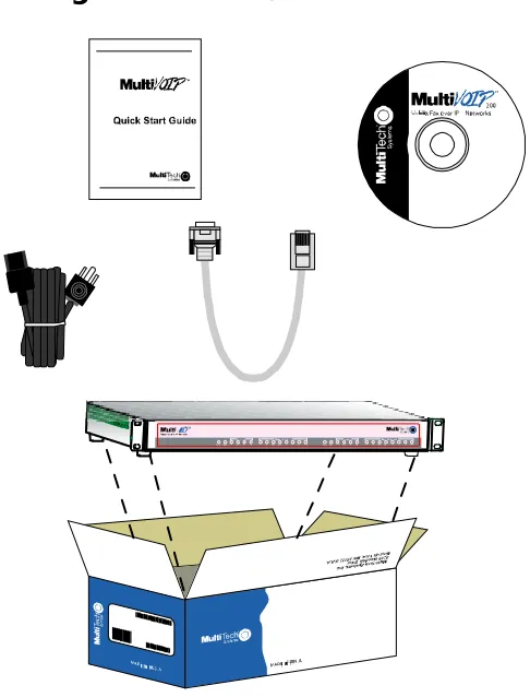
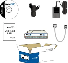
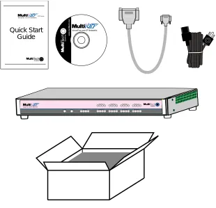
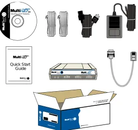
UNPACKING YOUR MULTIVOIP... 61
Unpacking the MVP2410/3010... 61
Unpacking the MVP2400... 62
Unpacking the MVP410/810... 63
Unpacking the MVP210... 64
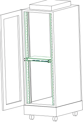
RACK MOUNTING INSTRUCTIONS FOR MVP2410/3010 & MVP410/810 ... 65
Safety Recommendations for Rack Installations ... 66
19-Inch Rack Enclosure Mounting Procedure... 67
CABLING... 68
Cabling Procedure for MVP2410/3010... 68
Cabling Procedure for MVP2400 ... 69
Cabling Procedure for MVP410/810... 70
Cabling Procedure for MVP210 ... 72
CHAPTER 4: SOFTWARE INSTALLATION ... 74
INTRODUCTION... 75
LOADING MULTIVOIP SOFTWARE ONTO THE PC... 75
UN-INSTALLING THE MULTIVOIP CONFIGURATION SOFTWARE... 82
CHAPTER 5: TECHNICAL CONFIGURATION FOR DIGITAL T1/E1 MULTIVOIPS (MVP2400, MVP2410, MVP3010) ... 86
CONFIGURING THE DIGITAL T1/E1 MULTIVOIP... 87
LOCAL CONFIGURATION... 89
Pre-Requisites... 89
IP Parameters...89
T1 Telephony Parameters (for MVP2400 & MVP2410)...90
E1 Telephony Parameters (for MVP3010) ...91
SMTP Parameters (for email call log reporting)...92
Local Configuration Procedure (Summary) ... 93
Local Configuration Procedure (Detailed)... 94
CHAPTER 6: TECHNICAL CONFIGURATION FOR ANALOG MULTIVOIPS (MVP210/410/810)... 161
CONFIGURING THE ANALOG MULTIVOIP ... 162
LOCAL CONFIGURATION... 165
Pre-Requisites... 165
IP Parameters...165
Analog Telephony Interface Parameters (for MVP210/410/810) ...166
SMTP Parameters (for email call log reporting)...167
CHAPTER 7: T1 PHONEBOOK CONFIGURATION ... 235
CONFIGURING THE MVP2400/2410 MULTIVOIP PHONEBOOKS... 236
T1 PHONEBOOK EXAMPLES... 254
3 Sites, All-T1 Example... 254
Configuring Mixed Digital/Analog VOIP Systems ... 260
Call Completion Summaries ... 270
Variations in PBX Characteristics... 273
CHAPTER 8: E1 PHONEBOOK CONFIGURATION ... 274
MVP3010 INBOUND AND OUTBOUND MULTIVOIP PHONEBOOKS... 275
Free Calls: One VOIP Site to Another... 276
Local Rate Calls: Within Local Calling Area of Remote VOIP ... 277
National Rate Calls: Within Nation of Remote VOIP Site ... 279
Inbound versus Outbound Phonebooks... 280
PHONEBOOK CONFIGURATION PROCEDURE... 284
E1 PHONEBOOK EXAMPLES... 298
3 Sites, All-E1 Example ... 298
Configuring Digital & Analog VOIPs in Same System... 305
Call Completion Summaries...314
Variations in PBX Characteristics... 317
International Telephony Numbering Plan Resources ... 318
CHAPTER 9: ANALOG PHONEBOOK CONFIGURATION ... 320
CHAPTER 10: OPERATION AND MAINTENANCE ... 322
OPERATION AND MAINTENANCE... 323
System Information screen... 323
Statistics Screens... 325
About Call Progress... 325
About Logs ... 331
About Reports ... 334
About IP Statistics... 335
About T1/E1 Statistics... 339
MULTIVOIP PROGRAM MENU ITEMS... 347
Date and Time Setup... 349
Obtaining Updated Firmware... 349
Implementing a Software Upgrade ... 353
Identifying Current Firmware Version ...353
Downloading Firmware...354
Downloading CAS Protocol ...357
Downloading Factory Defaults...360
Setting and Downloading User Defaults ... 362
WEB BROWSER INTERFACE... 381
SYSLOG SERVER FUNCTIONS... 386
CHAPTER 11: WARRANTY, SERVICE, AND TECH SUPPORT... 389
LIMITED WARRANTY... 390
REPAIR PROCEDURES FOR U.S. AND CANADIAN CUSTOMERS... 390
TECHNICAL SUPPORT... 392
Contacting Technical Support ... 392
CHAPTER 12: REGULATORY INFORMATION ... 393
EMC, Safety, and R&TTE Directive Compliance ... 394
FCC DECLARATION... 394
Industry Canada ... 395
FCC Part 68 Telecom ... 395
Canadian Limitations Notice ... 396
APPENDIX A: EXPANSION CARD INSTALLATION (MVP24-48 & MVP30-60)... 397
INSTALLATION... 398
OPERATION... 400
APPENDIX B: CABLE PINOUTS ... 401
APPENDIX B: CABLE PINOUTS... 402
Command Cable ... 402
Ethernet Connector... 402
T1/E1 Connector... 403
Voice/Fax Channel Connectors ... 403
APPENDIX C: TCP/UDP PORT ASSIGNMENTS ... 405
WELL KNOWN PORT NUMBERS... 406
PORT NUMBER ASSIGNMENT LIST... 406
APPENDIX D: INSTALLATION INSTRUCTIONS FOR MVP428 UPGRADE CARD... 407
About This Manual
This manual is about Voice-over-IP products made by Multi-Tech Systems, Inc. It describes three product groups.
1. T1 Digital MultiVOIP units, models MVP2400, MVP2410, and the capacity-doubling add-on expansion card, model MVP24-48.
2. E1 Digital MultiVOIP units, models, MVP3010 and the capacity-doubling add-on expansion card, model MVP30-60. 3. Analog MultiVOIP units, models MVP810, MVP410, and
MVP210.
The table below describes the vital characteristics of these various models.
MultiVOIP Product Family
Variable Model/Version Icon and Typography. The MultiVOIP product family is a coordinated set of products that can operate with each other in a seamless fashion. For example, both the digital and analog MultiVOIP units use the same graphic user interface (GUI) in the MultiVOIP configuration software and both operate under a single GUI in the MultiVoipManager remote management software. Because this is the case, the various model numbers and version numbers of MultiVOIP family products will each appear in various dialog boxes and commands. But instead of showing these dialog boxes once for each model in this manual, we substitute the following icon.
Figure 1-1: Variable Model/Version Icon
It indicates that, whatever MultiVOIP model you are using, all details except the very model and version numbers themselves will be the same regardless of the MultiVOIP model used. Also, in some cases, we will use other typographic devices, like blank underlining
Introduction to TI MultiVOIPs (MVP2400,
MVP2410, & MVP24-48)
We proudly present MultiTech’s T1 Digital Multi-VOIP products. The MVP2400 is a table-top model; the MVP2410 is a rack-mount model; and the MVP24-48 is an add-on expansion card that doubles the capacity of the MVP2410 without adding another chassis. All of these voice-over-IP products have fax capabilities. All adhere to the North American standard of T1 trunk telephony using digital 24-channel time-division multiplexing, which allows 24 phone conversations to occur on the T1 line simultaneously. All can also accommodate T1 lines of the ISDN Primary Rate Interface type (ISDN-PRI).
Scale-ability. The MVP2400 and MVP2410 are tailored to companies needing more than a few voice-over-IP lines, but not needing carrier-class equipment. When expansion is needed, the MVP2410 can be field-upgraded into a dual T1 unit by installing the MVP24-48 kit, which is essentially a second MultiVOIP motherboard that fits in an open expansion-card slot in the MVP2410. The upgraded dual unit then accommodates two T1 lines.
T1 VOIP Traffic. The MVP2400/2410 accepts its outbound traffic from a T1 trunk that’s connected to either a PBX or to a telco/carrier. The MVP2400/2410 transforms the telephony signals into IP packets for transmission on LANs, WANs, or the Internet. Inbound IP data traffic is converted to telephony data and signaling.
When connected to PBX. When connected to a PBX, the
MVP2400/2410 creates a network node served by 10/100-Base T connections. Local PBX phone extensions gain toll-free access to all phone stations directly connected to the VOIP network. Phone extensions at any VOIP location also gain toll-free access to the entire local public-switched telephone network (PSTN) at every other VOIP location in the system.
When connected to PSTN. When the T1 line(s) connected to the MVP2400/2410 are connected directly to the PSTN, the unit becomes a Point-of-Presence server dedicated to local calls off-net.
Identification, Call Forwarding (from the H.450 standard), and Call Transfer (H.450.2 from H.323 Version 2). The fourth version of the H.323 standard improves system resource usage (esp. logical port or socket usage) by handling call signaling more compactly and allowing use of the low-overhead UDP protocol instead of the error-correcting TCP protocol where possible.
The MultiVOIP is also SIP-compatible. However, H.450 Supplementary Services features can be used under H.323 only and not under SIP.
The MultiVOIP2400/2410 comes equipped with a variety of data compression capabilities, including G.723, G.729, and G.711 and features DiffServ quality-of-service (QoS) capabilities.
VOIP Functions. The MultiVOIP MVP2400/2410 gateway performs
four basic functions: (a) it converts a dialed number into an IP address, (b) it sends voice over the data network, (c) it establishes a connection with another VOIP gateway at a remote site, and (d) it receives voice over the data network. Voice is handled as IP packets with a variety of compression options. Each T1 connection to the MultiVOIP provides 24 time-slot channels to connect to the telco or to serve phone or fax stations connected to a PBX.
Ports. The MVP2400/2410 also has a 10/100 Mbps Ethernet LAN
interface, and a Command port for configuration. An MVP2410
upgraded with the MVP24-48 kit will have two Ethernet LAN interfaces and two Command ports.
Management. Configuration and system management can be done
locally with the MultiVOIP configuration software. After an IP address has been assigned locally, other configuration can be done remotely using the MultiVOIP web browser GUI. Remote system management can be done with the MultiVoipManager SNMP software or via the MultiVOIP web browser GUI. All of these control software packages
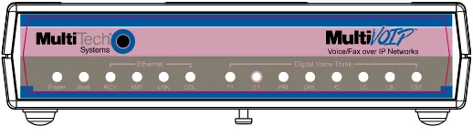
T1 Front Panel LEDs
The MVP2400, MVP2410, and MVP24-48 all use a common main circuit board or motherboard. Consequently the LED indicators are the same for all.
Figure 1-2. MultiVOIP MVP2400 Front Panel
Active LEDs. The MVP2410 front panel has two sets of identical LEDs. In the MVP2410 as shipped (that is, without an expansion card), the left-hand set of LEDs is functional whereas the right-hand set is not.
When the MVP2410 has been upgraded with an MVP24-48 kit, the right-hand set of LEDs will also become active.
T1 LED Descriptions
The descriptions below apply to all digital T1 MultiVOIP units.
MVP2400/2410 Front Panel LED Definitions
MVP2400/2410 Front Panel LED Definitions
LED NAME DESCRIPTION
Power Indicates presence of power.
Boot After power up, the Boot LED will be on for about 10 seconds while the MVP2400/2410 is booting.
RCV Receive. Lights when receiving data on Ethernet
port.
XMT Transmit. Lights when transmitting data on
Ethernet port.
LNK Link. When lit, VOIP “sees” the hub or network
via the Ethernet connection.
COL Collision. Lit when data collisions occur.
T1 When lit, indicates presence of T1 connection.
E1 E1. Not supported.
PRI PRI. On if T1 line is of ISDN-Primary-Rate type.
ONL Online. This LED is on when frame
synchronization has been established on the T1/E1 link.
IC IC LED is on when Internal Clocking is selected in
T1/E1 configuration.
LC Indicates Loss of Carrier.
LS Indicates Loss of Signal.
Introduction to EI MultiVOIPs
(MVP3010 & MVP30-60)
We proudly present MultiTech’s E1 Digital Multi-VOIP products. The MVP3010 is a rack-mount model and the MVP30-60 is an add-on expansion card that doubles the capacity of the MVP3010 without adding another chassis. All of these voice-over-IP products have fax capabilities. All adhere to the European standard of E1 trunk telephony using digital 30-channel time-division multiplexing, which allows 30 phone conversations to occur on the E1 line simultaneously. All can also accommodate E1 lines of the ISDN Primary Rate Interface type (ISDN-PRI).
Scale-ability. The MVP3010 is tailored to companies needing more than a few voice-over-IP lines, but not needing carrier-class equipment. When expansion is needed, the MVP3010 can be field-upgraded into a dual E1 unit by installing the MVP30-60 kit, which is essentially a second MultiVOIP motherboard that fits into an open expansion-card slot in the MVP3010. The upgraded dual unit then accommodates two E1 lines.
E1 VOIP Traffic. The MVP3010 accepts its outbound traffic from a E1 trunk that’s connected to either a PBX or to a telco/carrier. The MVP3010 transforms the telephony signals into IP packets for
transmission on LANs, WANs, or the Internet. Inbound IP data traffic is converted to telephony data and signaling.
When connected to PBX. When connected to a PBX, the MVP3010
creates a network node served by 10/100-Base T connections. Local PBX phone extensions gain toll-free access to all phone stations directly connected to the VOIP network. Phone extensions at any VOIP location also gain local-rate access to the entire local public-switched telephone network (PSTN) at every other VOIP location in the system.
When connected to PSTN. When the E1 line(s) connected to the MVP3010 are connected directly to the PSTN, the unit becomes a Point-of-Presence server dedicated to local calls off-net.
H. 323 & SIP. Being H.323 compatible, the MVP3010 can place calls to telephone equipment at remote IP network locations that also contain H.323 compatible voice-over-IP gateways. It will interface with H.323 software and H.323 gatekeeper units. H.323 specifications also bring to voip telephony many special features common to conventional
H.323 Version 2). The fourth version of the H.323 standard improves system resource usage (esp. logical port or socket usage) by handling call signaling more compactly and allowing use of the low-overhead UDP protocol instead of the error-correcting TCP protocol where possible.
The MultiVOIP is also SIP-compatible. However, H.450
Supplementary Services features can be used under H.323 only and not under SIP.
The MultiVOIP3010 comes equipped with a variety of data compression capabilities, including G.723, G.729, and G.711 and features DiffServ quality-of-service (QoS) capabilities.
VOIP Functions. The MultiVOIP MVP3010 gateway performs four
basic functions: (a) it converts a dialed number into an IP address, (b) it sends voice over the data network, (c) it establishes a connection with another VOIP gateway at a remote site, and (d) it receives voice over the data network. Voice is handled as IP packets with a variety of compression options. Each E1 connection to the MultiVOIP provides 30 time-slot channels to connect to the telco or to serve phone or fax stations connected to a PBX.
Ports. The MVP3010 also has a 10/100 Mbps Ethernet LAN interface, and a Command port for configuration. An MVP3010 upgraded with the MVP30-60 kit will have two Ethernet LAN interfaces and two Command ports.
Management. Configuration and system management can be done
locally with the MultiVOIP configuration software. After an IP address has been assigned locally, other configuration can be done remotely using the MultiVOIP web browser GUI. Remote system management can be done with the MultiVoipManager SNMP software or via the MultiVOIP web browser GUI. All of these control software packages are included on the Product CD.
E1 Front Panel LEDs
Because the MVP3010 and MVP30-60 both use a common main circuit card or motherboard, the LED indicators are the same for both.
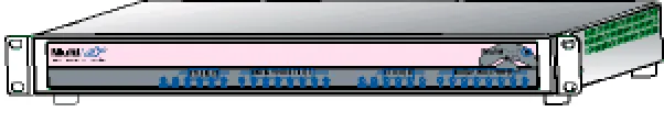
Figure 1-4. MultiVOIP MVP3010 Chassis
Active LEDs. The MVP3010 front panel has two sets of identical LEDs. In the MVP3010 as shipped (that is, without an expansion card), the left-hand set of LEDs is functional whereas the right-hand set is not.
When the MVP3010 has been upgraded with an MVP30-60 kit, the right-hand set of LEDs will also become active.
E1 LED Descriptions
MVP3010 Front Panel LED Definitions
MVP3010 Front Panel LED Definitions
LED NAME DESCRIPTION
Power Indicates presence of power.
Boot After power up, the Boot LED will be on for about 10 seconds while the MVP3010 is booting.
RCV Receive. Lights when receiving data on Ethernet
port.
XMT Transmit. Lights when transmitting data on
Ethernet port.
LNK Link. When lit, VOIP “sees” the hub or network
via the Ethernet connection.
MVP3010 Front Panel LED Definitions (cont’d)
T1 T1. Not supported.
E1 E1. When lit, indicates presence of E1
connection.
PRI PRI. On if E1 line is of ISDN-Primary-Rate type.
ONL Online. This LED is on when frame
synchronization has been established on the T1/E1 link.
IC IC LED is on when Internal Clocking is selected
in T1/E1 configuration.
LC Indicates Loss of Carrier.
LS Indicates Loss of Signal.
Test For testing purposes only. For testing purposes
Introduction to Analog MultiVOIPs
(MVP-210/410/810 & MVP428)
VOIP: The Free Ride. We proudly present Multi-Tech's MVP-210/410/810 generation of MultiVOIP Voice-over-IP Gateways. They allow voice/fax communication to be transmitted at no additional expense over your existing IP network, which has ordinarily been data-only. To access this free voice and fax communication, you simply connect the MultiVOIP to your telephone equipment and your existing Internet connection. These analog MultiVOIPs inter-operate readily with T1 or E1 MultiVOIPs units.
Capacity. The MultiVOIP model MVP810 is a eight-channel unit, the MVP410 a four-channel unit, and the MVP210 a two-channel unit. All of these MultiVOIP units have a 10/100Mbps Ethernet interface and a command port for configuration. The MVP428 is an expansion circuit card for the four-channel MVP410 that turns it into an eight-channel voip.
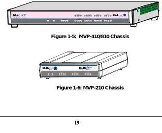
Mounting. Mechanically, the MVP410 and MVP810 MultiVOIPs are
designed for a one-high industry-standard EIA 19-inch rack enclosure. By contrast, the MVP210 is a table-top unit. The product must be installed by qualified service personnel in a restricted-access area, in accordance with Articles 110-16, 10-17, and 110-18 of the National Electrical Code, ANSI/NFPA 70.
Phone System Transparency. These MultiVOIPs inter-operate with a telephone switch or PBX, acting as a switching device that directs voice and fax calls over an IP network. The MultiVOIPs have “phonebooks,” directories which determine to who calls may be made and the
sequences that must be used to complete calls through the MultiVOIP. The phonebooks allow the phone user to interact with the VOIP system just as they would with an ordinary PBX or telco switch. When the phonebooks are set, special dialing sequences are minimized or eliminated altogether. Once the call destination is determined, the phonebook settings determine whether the destination VOIP unit must strip off or add dialing digits to make the call appear at its destination to be a local call.
H.323 & SIP. The MultiVOIP supports the H.323 standards-based protocol enabling your MultiVOIP to participate in real-time
conferencing with other third-party VOIP Gateways or endpoints that
support the H.323 protocol (for example, Microsoft NetMeeting® ). The
H.323 specifications also bring to voip telephony many special features common to conventional telephony. H.323 features of this kind that have been implemented into the MuliVOIP include Call Hold, Call Waiting, Call Identification, Call Forwarding (from the H.450 standard), and Call Transfer (H.450.2 from H.323 Version 2). The fourth version of the H.323 standard improves system resource usage (esp. logical port or socket usage) by handling call signaling more compactly and allowing use of the low-overhead UDP protocol instead of the error-correcting TCP protocol where possible.
The MultiVOIP is also SIP-compatible. However, H.450 Supplementary Services features can be used under H.323 only and not under SIP.
Gatekeepers. Gatekeeper software is optional and when used in a network, it typically resides on a designated PC. It acts as the central point for all calls within its zone and provides call control services to all registered endpoints. In addition, Gatekeepers can perform bandwidth management through support for Bandwidth Request, Confirm, and Reject messages.
Management. Configuration and system management can be done
locally with the MultiVOIP configuration software. After an IP address has been assigned locally, other configuration can be done remotely using the MultiVOIP web browser GUI. Remote system management can be done with the MultiVoipManager SNMP software or via the MultiVOIP web browser GUI. All of these control software packages are included on the Product CD.
R C VX M TC OLLN K X MTRC VX S GR SG X M TR CVXS GRS G X MTRC VX S GR SG XM TR C VX SGRS G
XM TR C VX SGRS G X MTRC VX S GR SG X MTRC VX S GR SG
Voi ce/Fax 5 Voice/ Fax 6 Voice/Fax 7 Voi ce/ Fax 8 Voice/Fax 1 Voice/ Fax 2 Voice/Fax 3 Voi ce/ Fax 4 Ether net
Boot Power
X M TR CVXS GRS G
Analog MultiVOIP Front Panel LEDs
LED Types. The MultiVOIPs have two types of LEDs on their front panels:
(1) general operation LED indicators (for power, booting, and ethernet functions), and
(2) channel operation LED indicators which describe the data traffic and performance in each VOIP data channel.
Active LEDs. On both the MVP410 and MVP810, there are eight sets of channel-operation LEDs. However, on the MVP410, only the lower four sets of channel-operation LEDs are functional. On the MVP810, all eight sets are functional.
RCVXMTCOLLNK XMTRCVXSGRSG
XMTRCVXSGRSG XMTRCVXSGRSG XMTRCVXSGRSG
XMTRCVXSGRSG XMTRCVXSGRSG
XMTRCVXSGRSG
Voice/Fax 5 Voice/Fax 6 Voice/Fax 7 Voice/Fax 8 Voice/Fax 1 Voice/Fax 2 Voice/Fax 3 Voice/Fax 4 Ethernet
Boot Power
XMTRCVXSGRSG
Figure 1-7. MVP410/810 Front Panel
Similarly, the MVP210 has the general-operation indicator LEDs and two sets of channel-operation LEDs, one for each channel.
Analog MultiVOIP LED Descriptions
MVP-210/410/810 Front Panel LED Definitions
LEDNAMEDESCRIPTION
General Operation LEDs(one set on each MultiVOIP model)
Power Indicates presence of power.
Boot After power up, the Boot LED will be on briefly while the MultiVOIP is booting. It lights whenever the MultiVOIP is booting or downloading a setup configuration data set. Ethernet RCV. Receive. Lights (blinks) when receiving data on
Ethernet port.
XMT. Transmit. Lights (blinks) when transmitting data on Ethernet port. ..
LNK. Link. When lit, VOIP “sees” the hub or network via the Ethernet connection. ..
COL. Collision. Lit when data collisions occur. ..
Channel-Operation LEDs (one set for each channel)
XMT Transmit. This indicator blinks when voice packets
are being transmitted to the local area network.
RCV Receive. This indicator blinks when voice packets
are being received from the local area network.
XSG Transmit Signal. This indicator lights when the
FXS-configured channel is off-hook, the FXO-FXS-configured channel is receiving a ring from the Telco, or the M lead is active on the E&M configured channel. That is, it lights when the MultiVOIP is receiving a ring from the PBX.
RSG Receive Signal. This indicator lights when the
Computer Requirements
The computer on which the MultiVOIP’s configuration program is installed must meet these requirements:
• must be IBM-compatible PC with MS Windows operating
system;
• must have an available COM port for connection to the
MultiVOIP.
Specifications
Specs for Digital T1 MultiVOIP Units
Digital T1 MultiVOIP Specifications
Parameter
……/Model
MVP-2400
MVP-2410
MVP-2410
w/ MVP24-48
Expansion
Card
Operating Voltage(s)External
transformer:
1.6A@5v100-240 VAC
1.2 - 0.6 A
100-240 VAC
1.2 - 0.6 A
Mains Frequencies
50/60 Hz
50/60 Hz
50/60 Hz
Power
Consumption
13 watts
17 watts
27 watts
Mechanical Dimensions
6.2” W x
9” D x
1.4” H
15.8cm W x
22.9cm D x
3.6cm H
1.75”H x
17.4”W x
8.75”D
4.5cm H x
44.2 cm W x
22.2 cm D
1.75”H x
17.4”W x
8.75”D
4.5cm H x
44.2 cm W x
22.2 cm D
Specs for Digital E1 MultiVOIP Units
Digital E1 MultiVOIP Specifications
Parameter
……/Model
MVP-3010
MVP-3010
w/ MVP30-60
Expansion
Card
Operating Voltage(s)
100-240 VAC
1.2 - 0.6 A
100-240 VAC
1.2 - 0.6 A
MainsFrequencies
50/60 Hz
50/60 Hz
Power
Consumption
17 watts
27 watts
Mechanical Dimensions
1.75”H x
17.4”W x
8.75”D
4.5cm H x
44.2 cm W x
22.2 cm D
1.75”H x
17.4”W x
8.75”D
4.5cm H x
44.2 cm W x
22.2 cm D
Weight
7.1 lbs.
(3.2 kg)
Specs for Analog MultiVOIP Units
Analog MultiVOIP Specifications
Parameter
……/Model
MVP210
MVP410
MVP810
or
MVP410 + 428
Operating Voltage(s) External transformer: 3A @5V
100-240 VAC
1.2 - 0.6 A
100-240 VAC
1.2 - 0.6 A
Mains Frequencies
50/60 Hz
50/60 Hz
50/60 Hz
Power
Consumption
19 watts 29 watts 46 watts
Mechanical Dimensions
6.2” W x 9” D x 1.4” H
15.8cm W x 22.9cm D x 3.6cm H
1.75”H x 17.4”W x 8.5”D
4.5cm H x 44.2 cm W x 21.6 cm D
1.75”H x 17.4”W x 8.5”D
4.5cm H x 44.2 cm W x 21.6 cm D
Weight 1.8lbs (.82kg)
Installation at a Glance
The basic steps of installing your MultiVOIP network involve unpacking the units, connecting the cables, and configuring the units using management software (MultiVOIP Configuration software) and confirming connectivity with another voip site. This process results in a fully functional Voice-Over-IP network.
Related Documentation
The MultiVOIP User Guide (the document you are now reading) comes in electronic form and is included on your system CD. It presents in-depth information on the features and functionality of Multi-Tech’s MultiVOIP Product Family.
The CD media is produced using Adobe AcrobatTM for viewing and
printing the user guide. To view or print your copy of a user guide,
load Acrobat ReaderTM on your system. The Acrobat Reader is included
on the MultiVOIP CD and is also a free download from Adobe’s Web Site:
www.adobe.com/prodindex/acrobat/readstep.html
This MultiVOIP User Guide is also available on Multi-Tech’s Web site at:
http://www.multitech.com
Viewing and printing a user guide from the Web also requires that you have the Acrobat Reader loaded on your system. To select the MultiVOIP User Guide from the Multi-Tech Systems home page, click Documents and then click
MultiVOIP Family in the product list drop-down window. All documents for this MultiVOIP Product Family will be displayed. You can then choose User Guide
Introduction
This chapter gets the MultiVOIP up and running quickly. The details we’ve skipped to make this brief can be found elsewhere in the manual (see Table of Contents and Index).
MultiVOIP Startup Tasks
Task
Summary●
●
●
●
Collecting Phone/IP
Details (vital!)
The MultiVOIP must be configured to interface with your particular phone system and IP network. To do so, certain details must be known about those phone and IP systems.
●
●
●
●
Placement
Decide where you’ll mount the voip.●
●
●
●
The Command/Control
Computer:
Specs & Settings
Some modest minimum specifications must be met. A COM port must be set up.
●
●
●
●
Hookup
Connect power, phone, and data cablesper diagram.
●
●
●
●
Software Installation
This is the configuration program. It’s a standard Windows software installation.●
●
●
●
Phone/IP Starter
Configuration
You will enter phone numbers and IP addresses. You’ll use default parameter values where possible to get the system running quickly.
●
●
●
●
Phonebook Starter
Configuration
The phonebook is where you specify how calls will be routed. To get the system running quickly, you’ll make phonebooks for just two voip sites.
●
●
●
Phone/IP Details *Absolutely Needed*
Before Starting the Installation
Gather IP Information
➼ Ask your computer network
administrator.
Info needed to operate:
all MultiVOIP models.
IP Network Parameters: Record for each VOIP Site in System
@
• IP Address
• IP Mask
• Gateway
• Domain Name Server (DNS) Info (not implemented; for future use)
Gather Telephone Information
➼ T1 Phone Parameters
Ask phone company or PBX maintainer.
Info needed to operate:
MVP2400 MVP2410
T1 Telephony Parameters: Record for this VOIP Site
@
• Which frame format is used? ESF___ or D4___
• Which CAS or PRI protocol is used? ______________
• Clocking: Does the PBX or telco switch use
internal or external clocking? _________________ Note that the setting used in the voip unit will be the opposite of the setting used by the telco/PBX.
• Which line coding is used? AMI___ or B8ZS___
Phone/IP Details *Absolutely Needed*
(cont’d)
Gather Telephone Information
➼ E1 Phone Parameters
Ask phone company or PBX maintainer.
Info needed to operate:
MVP3010
E1 Telephony Parameters: Record for this VOIP Site
@
• Which frame format is used? Double Frame_____ MultiFrame w/ CRC4_____ MultiFrame w/ CRC4 modified_____
• Which CAS or PRI protocol is used? ______________
• Clocking: Does the PBX or telco switch use internal or external clocking? _________________ Note that the setting used in the voip unit will be the opposite of the setting used by the telco/PBX.
• Which line coding is used? AMI___ or HDB3___
• Pulse shape level?: (most commonly 0 to 40 meters)
Gather Telephone Information
➼ Analog Phone Parameters
Ask phone company or telecom manager.
Needed for:
MVP810 MVP410 MVP210
Analog Telephony Interface Parameters: Record for this VOIP Site
@
• Which interface type (or “signaling”) is used? E&M_____ FXS/FXO_____
• If FXS, determine whether the line will be used for a phone, fax, or KTS (key telephone system)
• If FXO, determine if line will be an analog PBX extension or an analog line from a telco central office
• If E&M, determine these aspects of the E&M trunk line from the PBX:
• What is its Type (1, 2, 3, 4, or 5)?
Phone/IP Details Often Needed/Wanted
Obtain Email Address for VOIP
(for email call log reporting)
required if log reports of VOIP call traffic are to be sent by email
Optional
SMTP Parameters
Preparation Task:
Ask Mail Server administrator to set up email account (with password) for the MultiVOIP unit itself. Be sure to give a unique identifier to each individual MultiVOIP unit.
Get the IP address of the mail server computer, as well.
To: I.T. Department re: email account for VOIP
Identify Remote VOIP Site to Call
When you’re done installing the MultiVOIP, you’ll want to confirm that it is configured and operating properly. To do so, it’s good to have another voip that you can call for testing purposes. You’ll want to confirm end-to-end connectivity. You’ll need IP and telephone information about that remote site.
If this is the very first voip in the system, you’ll want to coordinate the installation of this MultiVOIP with an installation of another unit at a remote site.
Identify VOIP Protocol to be Used
Placement
Mount your MultiVOIP in a safe and convenient location where cables for your network and phone system are accessible. Rack-mounting instructions are in Chapter 3: Mechanical Installation & Cabling.
The Command/Control Computer (Specs & Settings)
The computer used for command and control of the MultiVOIP (a) must be an IBM-compatible PC,
(b) must use a Microsoft operating system,
(c) must be connected to your local network (Ethernet) system, and (d) must have an available serial COM port.
The configuration tasks and control tasks the PC will have to do with the MultiVOIP are not especially demanding. Still, we recommend using a reasonably new computer. The computer that you use to configure your MultiVOIP need not be dedicated to the MultiVOIP after installation is complete.
COM port on controller PC. You’ll need an available COM port on the
Quick Hookups
Hookup for MVP2410 & MVP3010
Digital Voice
Trunk O
l
10 /100 RS-232
Ethernet Command Cabling to your IP network. RJ-45 connector. T1/E1/PRI cabling to your PBX,
and/or to the PSTN. RJ-45 connector.
On/Off Switch Power Cable
Receptacle Cabling to computer running
MultiVOIP software. RJ-45 to serial connector (DB9).
Grounding Screw
T1/E1 MultiVOIP Hookup
(MVP-2410/3010)
Hookup for MVP410 & MVP810
E&M FXS/FXO E&M FXS/FXO E&M FXS/FXO E&M FXS/FXO E&M FXS/FXO E&M FXS/FXO E&M FXS/FXO E&M FXS/FXO Grounding Screw: Connect to Earth Ground On/Off Switch Power Cable Receptacle
Cabling to your IP network. RJ-45 connector. Cabling to computer running
MultiVOIP software. Connector at MultiVOIP: DB-25.
Connector at computer: DB-9.
Cabling to phone equipment. MVP810 has 8 connector pairs. MVP410 has 4 connector pairs. Only 1 connector of any pair is used at a time.
Analog MultiVOIP Hookup
MVP-410/810
E&M (RJ-45 connector): connects to E&M trunk line from PBX or telco office.
FXS (RJ-11 connector): connects to phone, fax, or key phone system.
FXO (RJ-11 connector): connects to analog phone line or analog PBX extension.
Hookup for MVP2400
Power Connection
Command Port Connection 1
0 DIGITAL VOICE
TRUNK
ETHERNET
10/100 RS232 COMMAND
POWER
T1
PBX
PSTN
Telephony Connection
Network Connection
:
Hub
Hookup for MVP210
10BASET COMMAND PORT POWER
Ethernet Connection Command Port Connection Power Connection
E&M
FXS/FXO FXS/FXO RS232
COMMAND
10/100 POWER
ETHERNET
E&M
Voice/Fax Channel 1 - 2 Connections
GND
PSTN
E&M FXO
FXS E&M FXO/FXS
Load MultiVOIP Control Software onto PC
For more details, see Chapter 4: Software Installation.
1. MultiVOIP must be properly cabled. Power must be turned on.
2. Insert MultiVOIP CD into drive. Allow 10-20 seconds for Autorun to start. If Autorun fails, go to
My Computer | CD ROM drive | Open. Click Autorun icon.
3. At first dialog box, click Install Software.
4. At ‘welcome’ screen, click Next.
5. Follow on-screen instructions. Accept default program folder location and click Next.
6. Accept default icon folder location. Click Next. Files will be copied.
7. Select available COM port on command/control computer.
8. At completion screen, click Finish.
Phone/IP Starter Configuration
Full details here:
MVP2400 MVP2410 MVP3010
Chapter 5: Technical Configuration for Digital T1/E1 MultiVOIPs
MVP210 MVP410 MVP810
Chapter 6: Technical Configuration for Analog MultiVOIPs
1. Open MultiVOIP program: Start | MultiVOIP xxx | Configuration.
2. Go to Configuration | IP. Enter the IP parameters for your voip site.
3. Do you want to configure and operate the MultiVOIP unit using the web browser GUI? (It has the same functionality as the local
Windows GUI, but offers remote access.) If NO, skip to step 5.
If YES, continue with step 4.
4. Enable Web Browser GUI (Optional). To do configuration and operation procedures using the web browser GUI, you must first enable it. To do so, follow these steps.
A. Be sure an IP address has
been assigned to the
MultiVOIP unit (this must be done in the MultiVOIP Windows GUI).
E. Open web browser.
(Note: The PC being used must be connected to and have an IP address on the same IP network that the voip is on.)
B. Save Setup in Windows GUI. F. Browse to IP address of
MultiVOIP unit.
C. Close the MultiVOIP
Windows GUI.
G. If username and password
have been established, enter them when prompted by voip.
D. Install Java program from
MultiVOIP product CD.
NOTE: Required on first use of Web Browser GUI only.
H. Use web browser GUI to
configure or operate voip.
Need more info?
See “Web Browser Interface” in Operation &
5. Go to Configuration | Voice/Fax. Select Coder | “Automatic.” At the right-hand side of the dialog box, click Default. If you know any specific parameter values that will apply to your system, enter them. Click Copy Channel. Select Copy to All. Click Copy. At main Voice/Fax Parameters screen, click OK to exit from the dialog box.
6. Enter telephone system information.
Analog MultiVOIPs
MVP-210/410/810
Digital MultiVOIPs
MVP-2400/2410/3010
Go to
Configuration | Interface. Enter parameters obtained from phone company or PBX
administrator.
Go to
Configuration | T1/E1/ISDN. Enter parameters obtained from phone company or PBX
administrator.
7. Go to Configuration | Regional Parameters. Select the
Country/Region that fits your situation. Click Default and confirm. Click OK to exit from the dialog box.
8. Do you want the phone-call logs produced by the MultiVOIP to be sent out by email (to your Voip Administrator or someone else)? If NO, skip to step 10.
If YES, continue with step 9.
9. Go to Configuration | SMTP.
SMTP lets you send phone-call log records to the Voip Administrator by email. Select Enable SMTP.
You should have already obtained an email address for the MultiVOIP itself (this serves as the origination email account for email logs that the MultiVOIP can email out automatically).
Enter this email address in the “Login Name” field. Type the password for this email account.
Enter the IP address of the email server where the MultiVOIP’s email account is located in the “Mail Server IP Address” field.
Phone/IP Starter Configuration (continued)
9. (continued) Whenever email log messages are sent out, they must have a standard Subject line. Something like “Phone Logs for Voip N” is useful. If you have more than one MultiVoip unit in the building, you’ll need a unique identifier for each one (select a useful name or number for “N”). In this “Subject” field, enter a useful subject title for the log messages.
In the “Reply-To Address” field, enter the email address of your Voip Administrator.
10. Go to Configuration | Logs.
Select “Enable Console Messages.” (Not applicable if using Web GUI.)
To allow log reports by email (if desired), click SMTP. Click OK.
To do logging with a SysLog client program, click on “SysLog Server – Enable” in the Logs screen. To implement this function, you must install a SysLog client program. For more info, see the “SysLog Server Functions” section of the Operation & Maintenance chapter of the User Guide.
11. Enable premium (H.450) telephony features.
Go to Supplementary Services. Select any features to be used. For Call Hold, Call Transfer, & Call Waiting, specify the key sequence that the phone user will press to invoke the feature. For Call Name Identification, specify the allowed name types to be used and a caller-id descriptor.
If Call Forwarding is to be used, enable this feature in the
Add/Edit Inbound Phone Book screen.
12. Go to Save Setup | Save and Reboot. Click OK. This will save the parameter values that you have just entered.
The MultiVOIP’s “BOOT” LED will light up while the configuration file is being saved and loaded into the MultiVOIP. Don’t do anything to the MultiVOIP until the “BOOT “LED is off (a loss of power at this point could cause the MultiVOIP unit to lose the configuration settings you have made).
Phonebook Starter Configuration (with remote voip)
To do this part of the quick setup, you need to know of another voip that you can call to conduct a test. It should be at a remote location, typically somewhere outside of your building. You must know the phone number and IP address for that site. We are assuming here that the MultiVOIP will operate in conjunction with a PBX.
You must configure both the Outbound Phonebook and the Inbound Phonebook. A starter configuration only means that two voip locations will be set up to begin the system and establish voip communication.
Outbound Phonebook
1. Open the MultiVOIP program
(Start | MultiVOIP xxx | Configuration
2. Go to Phone Book | PhoneBook Modify | Outbound Phonebook | Add Entry.
3. On a sheet of paper, write down the calling code of the remote voip (area code, country code, city code, etc.) that you’ll be calling.
Follow the example that best fits your situation.
North America, Long-Distance Example
Euro, National Call Example
Technician in Seattle (area 206) must set up one voip there, another in Chicago (area 312, downtown).
Answer: Write down 312.
Technician in central London (area 0207) to set up voip there, another in Birmingham (area 0121).
Answer: write down 0121.
Euro, International Call Example
Technician in Rotterdam (country 31; city 010) to set up one voip there, another in Bordeaux (country 33; area 05).
4. Suppose you want to call a phone number outside of your building using a phone station that is an extension from your PBX system (if present). What digits must you dial? Often a “9” or “8” must be dialed to “get an outside line” through the PBX (i.e., to connect to the PSTN). Generally, “1 “or “11” or “0” must be dialed as a prefix for calls outside of the calling code area (long-distance calls, national calls, or international calls).
On a sheet of paper, write down the digits you must dial before you can dial a remote area code.
North America, Long-Distance Example
Euro, National Call Example
Seattle-Chicago system.
Seattle voip works with PBX that uses “8” for all voip calls. “1” must immediately precede area code of dialed number.
Answer: write down 81.
London/Birming. system.
London voip works with PBX that uses “9” for all out-of-building calls whether by voip or by PSTN. “0” must
immediately precede area code of dialed number.
Answer: write down 90.
Euro, International Call Example
Rotterdam/Bordeaux system.
Rotterdam voip works with PBX where “9” is used for all out-of-building calls. “0” must precede all international calls.
5. In the “Destination Pattern” field of the Add/Edit Outbound
Phonebook screen, enter the digits from step 4 followed by the digits from step 3.
North America, Long-Distance Example
Euro, National Call Example
Seattle-Chicago system.
Answer: enter 81312 as Destination Pat-tern in Outbound Phone-book of Seattle voip.
London/Birming. system. Leading zero of
Birmingham area code is dropped when combined with national-dialing access code. (Such
practices vary by country.)
Answer: enter 90121 as Destination Pat-tern in Outbound Phonebook of London voip.
Not 900121.
Euro, International Call Example
Rotterdam/Bordeaux system.
6. Tally up the number of digits that must be dialed to reach the remote voip site (including prefix digits of all types). Enter this number in the “Total Digits” field.
North America, Long-Distance Example
Euro, National Call Example Seattle-Chicago system.
To complete Seattle-to-Chicago call, 81312 must be followed by the 7-digit local phone number in Chicago.
Answer: enter 12 as number of Total Digits in Outbound Phone-book of Seattle voip.
London/Birming. system.
To complete London-to-Birmingham call, 90121 must be followed by the 7-digit local phone number in Birmingham.
Answer: enter 12 as number of Total Digits in Outbound Phone-book of London voip.
Euro, International Call Example Rotterdam/Bordeaux system.
To complete Rotterdam-to-Bordeaux call, 903305 must be followed by 8-digit local phone number in Bordeaux.
Answer: enter 14 as number of Total Digits in Outbound Phonebook of Rotterdam voip.
7. In the “Remove Prefix” field, enter the initial PBX access digit (“8” or “9”).
North America, Long-Distance Example
Euro, National Call Example Seattle-Chicago system.
Answer: enter 8 in “Remove Prefix” field of Seattle Outbound Phonebook.
London/Birming. system. Answer: enter 9 in “Remove
Prefix” field of London Outbound Phonebook.
Euro, International Call Example Rotterdam/Bordeaux system.
field in the Outbound Phonebook. This precludes the problem of having to make two inbound phonebook entries at remote voips, one to account for situations where “8” is used as the PBX access digit, and another for when “9” is used.
8. Select the voip protocol that you will use (H.323 or SIP).
9. Click OK to exit from the Add/Edit Outbound Phonebook screen.
Inbound Phonebook
1. Open the MultiVOIP program.
(Start | MultiVOIP xxx | Configuration
2. Go to Phone Book | PhoneBook Modify | Inbound Phonebook | Add Entry.
3. In the “Remove Prefix” field, enter your local calling code (area code, country code, city code, etc.) preceded by any other “access digits” that are required to reach your local site from the remote voip location (think of it as though the call were being made through the PSTN – even though it will not be).
North America, Long-Distance Example
Euro, National Call Example Seattle-Chicago system.
Seattle is area 206. Chicago employees must dial 81 before dialing any Seattle number on the voip system.
Answer: 1206 is prefix to be removed by local (Seattle) voip.
London/Birming. system.
Inner London is 0207 area. Birmingham employees must dial 9 before dialing any London number on the voip system.
Answer: 0207 is prefix to be removed by local (London) voip.
Euro, International Call Example Rotterdam/Bordeaux system.
Rotterdam is country code 31, city code 010. Bordeaux employees must dial 903110 before dialing any Rotterdam number on the voip system.
4. In the “Add Prefix” field, enter any digits that must be dialed from your local voip to gain access to the PSTN.
North America, Long-Distance Example
Euro, National Call Example Seattle-Chicago system.
On Seattle PBX, “9” is used to get an outside line.
Answer: 9 is prefix to be added by local (Seattle) voip.
London/Birming. system.
On London PBX, “9” is used to get an outside line.
Answer: 9 is prefix to be added by local (London) voip.
Euro, International Call Example Rotterdam/Bordeaux system.
On Rotterdam PBX, “9” is used to get an outside line.
Answer: 9 is prefix to be added by local (Rotterdam) voip.
6. In the “Description” field, it is useful to describe the ultimate destination of the calls. For example, in a New York City voip system, “incoming calls to Manhattan office,” might describe a phonebook entry, as might the descriptor “incoming calls to NYC local calling area.” The description should make the routing of calls easy to understand. (40 characters max.)
North America, Long-Distance Example
Euro, National Call Example Seattle-Chicago system.
Possible Description:. Free Seattle access, all employees
London/Birming. system.
Possible Description:. Local-rate London access, all empl.
Euro, International Call Example Rotterdam/Bordeaux system.
Possible Description:. Local-rate Rotterdam access, all empl.
7. Repeat steps 2-6 for each inbound phonebook entry. When all entries are complete, go to step 8.
8. Click OK to exit the inbound phonebook screen.
9. Click on Save Setup. Highlight Save and Reboot. Click OK.
Phonebook Tips
Preparing the phonebook for your voip system is a complex task that, at first, seems quite daunting. These tips may make the task easier.
1. Use Dialing Patterns, Not Complete Phone Numbers. You will not generally enter complete phone numbers in the voip phonebook. Instead, you’ll enter “destination patterns” that involve area codes and other digits. If the destination pattern is a whole area code, you’ll be assigning all calls to that area code to go to a particular voip which has a unique IP address. If your destination pattern includes an area code plus a particular local phone exchange number, then the scope of calls sent through your voip system will be narrowed (only calls within that local exchange will be handled by the designated voip, not all calls in that whole area code). In general, when there are fewer digits in your destination pattern, you are asking the voip to handle calls to more destinations.
2. The Four Types of Phonebook Digits Used. Important!
“Destination patterns” to be entered in your phonebook will generally consist of:
(a) calling area codes, (b) access codes,
(c) local exchange numbers, and (d) specialized codes.
Although voip phonebook entries may look confusing at first, it’s useful to remember that all the digits in any phonebook entry must be of one of these four types.
(b) access codes. There are digits (PSTN access codes) that must be dialed to gain access to an operator, to access the publicly switched ‘long-distance’ calling system(North America), to access the publicly switched ‘national’ calling system (Europe and elsewhere), or to access the publicly switched ‘international’ calling system (worldwide).
There are digits (PBX access codes) that must be dialed by phones connected to PBX systems or key systems. Often a “9” must be dialed on a PBX phone to gain access to the PSTN (‘to get an outside line’). Sometimes “8” must be dialed on a PBX phone to divert calls onto a leased line or to a voip system. However, sometimes PBX systems are ‘smart’ enough to route calls to a voip system without a special access code (so that “9” might still be used for all calls outside of the building).
There are also digits (special access codes) that must be dialed to gain access to a particular discount long-distance carrier or to some other closed or proprietary telephone system.
(c) local exchange numbers. Within any calling area there will be many local exchange numbers. A single exchange may be used for an entire small town. In cities, an exchange may be used for a particular neighborhood (although exchanges in cities do not always cover easily discernible areas). Organizations like businesses, governments, schools, and universities are also commonly assigned exchange numbers for their exclusive use. In some cases, these organizational-assigned exchanges can become non-localized because the exchange is assigned to one facility and linked, by the organization’s private network, to other sometimes distant locations.
(d) specialized codes. Some proprietary voip units assign, to sites and phone stations, numbers that are not compatible with PSTN
numbering. This can also occur in PBX or key systems. These specialized numbers must be handled on a case-by-case basis.
3. Knowing When to Drop Digits. Example
When calling area codes and access codes are used in
combination, a leading “1” or “0” must sometimes be dropped.
Phonebook Entry➠➠➠➠
Area code for Inner London is listed as “0207.” However, in international calls the leading “0” is dropped.
U.K. Country
4. Using a Comma. Detail
,
= 1-second pauseCommas are used in telephone dialing strings to indicate a pause to allow a dial tone to appear (common on PBX and key systems). Commas may be used only in the “Add Prefix” field of the Inbound Phonebook.
in many PBX systems (not needed in all)
5. Ease of Use. The phonebook setup determines how easy the voip system is to use. Generally, you’ll want to make it so dialing a voip call is very similar to dialing any other number (on the PSTN or through the PBX).
6. Avoid Unintentional Calls to Official/Emergency Numbers. Dialing a voip call will typically be somewhat different than ordinary dialing. Because of this, it’s possible to set up situations, quite unwittingly, where phone users may be predisposed to call official numbers without intending to do so. Conversely, a voip/PBX system might also make it difficult to place an official/emergency call when one intends to do so. Study your phonebook setup and do some dialing on the system to avoid these pitfalls.
7. Inbound/Outbound Pattern Matching. In general, the Inbound Phonebook entries of the local voip unit will match the Outbound Phonebook entries of the remote voip unit. Similarly, the Outbound Phonebook entries of the local voip unit will match the Inbound Phonebook entries of the remote voip unit. There will often be non-matching entries, but it’s nonetheless useful to notice the non-matching between the phonebooks.
Phonebook Example
Flagstaff Office 204.16.49.75 8-Channel Analog VoIP (MVP810) Area: 520Santa Fe Office
PBX System. Main Number: 444-3200 40 extensions PSTN 204.16.49.74 8-Channel Analog VoIP (MVP810) Area: 505 PBX System. Main Number: 333-2700 204.16.49.73 24-Channel Digital VoIP (MVP2410) PSTN Boise Office Area: 208 90 extensions IP Network
EachOutbound Phonebookcontains two pairs of entries, two entries for each remote site. Whenever an out-of-town employee dials a 12-digit number beginning with the listed 5-digit destination pattern (9+1+area code) of another company location, the PBX hands the call to the voip system. The local voip strips off the “9” and directs the call to the IP address of the remote voip. The remote voip receives the call and hands it to its PBX. The PBX then completes the call to the PSTN.
The one-digitOutbounddestination
patterns pertain to 3-digit calling between company employees.
Inbound Phonebook
One Common Situation
Voip Example. This company has offices in three
different cities. The PBX units all operate alike. Notably, they all give access to outside lines using “9.” They all are ‘smart’ enough to identify voip calls without using a special access digit (“8” is used in some systems). Finally, the system operates so that employees in any office can dial employees in any other office using only three digits. Here are the phonebooks needed for that system.
EachInbound Phonebook contains
two entries. The first entry (4 digits) specifies how incoming calls from the other voip sites will be handled if they go out onto the local PSTN. Essentially, all those calls come to the receiving voip with a pattern beginning with1+area code. The local voip removes those four digits because they aren’t needed when dialing locally. The local voip attaches a “9” at the beginning of the number to get an outside line. The PBX then completes the call to the PSTN.
The secondInbound Phonebook entry
(8 digits) is for receiving calls from company employees in the other two cities. The out-of-town employee simply dials 3 digits. The first of the three digits is uniquely used at each site and so acts as a destination pattern (Boise extensions are 7xx, Santa Fe extensions 2xx, Flagstaff extensions 6xx).
As the remote voip sends out the call, it automatically attaches all of the foregoing digits that would normally have to be dialed using the PSTN.
Flagstaff Voip Flagstaff Voip
Inbound Phonebook Outbound Phonebook
Prefix to Remove Prefix to Add Description Incoming Calls Destin. Pattern Total Digits Prefix to Remove Prefix to Add IP Addr Description Outgoing Calls
1520 9 Incoming calls to PSTN, Flagstaff local calls
91505 12 9 none 204.16 .49.74 Outgoing callsto Santa Fe
area 15207775 5 Incoming calls
to extensions of company’s PBX system in Flagstaff
2 3 none 1505 444 3
204.16 .49.74 3-digit calls toSanta Fe
employees 91208 12 9 none 204.16
.49.73 Outgoing callsto Boise area 7 3 none 1208
333 2
204.16 .49.73 3-digit calls toBoise
employees Flagstaff Office 204.16.49.75 8-Channel Analog VoIP (MVP810) PSTN PBX System. Main Number: 777-5600 30 extensions Area: 520 PBX System. Main Number: 333-2700 204.16.49.73 24-Channel Digital VoIP (MVP2410) PSTN Boise Office Area: 208 90 extensions
Santa Fe Office
PBX System. Main Number: 444-3200 40 extensions PSTN 204.16.49.74 8-Channel Analog VoIP (MVP810) Area: 505 IP Network
Santa Fe Voip Santa Fe Voip
Inbound Phonebook Outbound Phonebook
Prefix to Remove
Prefix to Add
Description Incoming Calls Destin.Pattern
Total Digits Prefix to Remove Prefix to Add IP Addr Description Outgoing Calls
1505 9, Incoming calls to PSTN, Santa Fe local calls
91208 12 9 none 204. 16.49. 73
Outgoing calls to Boise area 150544432 2 Incoming calls
to extensions of company’s PBX system in Santa Fe
7 3 none 1208 333 2 204.1 6.49. 73 Outgoing calls to extensions of company’s Boise PBX (3-digit dialing) 91520 12 9 none 204.
16.49. 75
Outgoing calls to Flagstaff area 6 3 none 1520
777 5
204. 16.49. 75
3-digit calls to Flagstaff employees
Boise Voip Boise Voip
Inbound Phonebook Outbound Phonebook
Prefix to Remove Prefix to Add Description Incoming Calls Destin. Pattern Total Digits Prefix to Remove Prefix to Add IP Addr Description Outgoing Calls
1208 9 Incoming calls to PSTN, Boise Area
91505 12 9 none 204.16 .49.74 Outgoing callsto Santa Fe
area 12083332 2 Incoming calls
to extensions of company’s PBX system in Boise
2 3 none 1505 444 3
204.16 .49.74
3-digit calls to Santa Fe employees 91520 12 9 none 204.1
6.49.7 5
Outgoing calls to Flagstaff area 6 3 none 1520
777 5
204.1 6.49.7 5
Sample Phonebooks Enlarged
Boise Voip Boise Voip Inbound Phonebook Outbound Phonebook
Prefix to Remove Prefix to Add Description Incoming Calls Destin. Pattern Total Digits Prefix to Remove Prefix to Add IP Addr Description Outgoing Calls
1208 9, Incoming calls to PSTN, Boise Area
91505 12 9 none 204. 16.49. 74
Outgoing calls to Santa Fe area 120833327 7 Incoming calls
to extensions of company’s PBX system in Boise
2 3 none 1505
444 3
204. 16.49. 74
3-digit calls to Santa Fe employees (extensions 200 to 240) 91520 12 9 none 204.
16.49. 75
Outgoing calls to Flagstaff area
6 3 none 1520
777 5
204. 16.49. 75
3-digit calls to Flagstaff employees (extensions 600-630)
Santa Fe Voip Santa Fe Voip Inbound Phonebook Outbound Phonebook
Prefix to Remove Prefix to Add Description Incoming Calls Destin. Pattern Total Digits Prefix to Remove Prefix to Add IP Addr Description Outgoing Calls 1505 9, Incoming calls
to PSTN, Santa Fe local calls
91208 12 9 none 204. 16.49. 73
Outgoing calls to Boise area
150544432 2 Incoming calls to extensions of company’s PBX system in Santa Fe
7 3 none 1208
333 2
204. 16.49. 73
3-digit calls to Boise employees (extensions 700-790) 91520 12 9 none 204.
16.49. 75
Outgoing calls to Flagstaff area
6 3 none 1520
777 5
204. 16.49. 75
3-digit calls to Flagstaff employees (extensions 600-630)
Flagstaff Voip Flagstaff Voip Inbound Phonebook Outbound Phonebook
Prefix to Remove Prefix to Add Description Incoming Calls Destin. Pattern Total Digits Prefix to Remove Prefix to Add IP Addr Description Outgoing Calls
1520 9, Incoming calls to PSTN, Flagstaff local calls
91505 12 9 none 204.16 .49.74
Outgoing calls to Santa Fe area
152077756 6 Incoming calls to extensions of company’s PBX system in Flagstaff
2 3 none 1505
444 3
204.16 .49.74
3-digit calls to Santa Fe employees (extensions 200-240) 91208 12 9 none 204.16
.49.73
Outgoing calls to Boise area
7 3 none 1208
333 2
204.16 .49.73
Phonebook Worksheet
Voip Location/ID:____________________________
Inbound Phonebook Outbound Phonebook Prefix to
Remove
Prefix to Add
Description
Incoming Calls Destin.Pattern Total Digits Prefix to Remove Prefix to Add IP Addr Description Outgoing Calls Other Details: Voip Location/ID:____________________________
Inbound Phonebook Outbound Phonebook Prefix to
Remove
Prefix to Add
Description
Incoming Calls Destin.Pattern Total Digits Prefix to Remove Prefix to Add IP Addr Description Outgoing Calls Other Details: Voip Location/ID:____________________________