Volume 8, No. 5, May-June 2017
International Journal of Advanced Research in Computer Science RESEARCH PAPER
Available Online at www.ijarcs.info
ISSN No. 0976-5697
Implications of Dependency Changes in Component Based Systems
Nisha Ratti
Department of CSE, Rayat Group of Institutions, Near Ropar, S.B.S.Nagar, Punjab, India
Parminder Kaur
Department of CSE, Guru Nanak Dev University, Amritsar, Punjab, India
Abstract: Software does evolve over a period of time. Various studies have been conducted to study this phenomenon. One of the important developments on software platform has been the emergence of Component Based Systems (CBSs). While studying the evolution of CBSs, it is suggested that their evolution cannot be studied without noticing the corresponding changes in the dependencies. Our study tries to measure quantitatively these changes over a period of time along with the usual changes in development aspects like coupling, cohesion etc.
Keywords: Software Evolution, Component Based Systems, Open Source Environment, Component Dependencies.
INTRODUCTION
Software ages with time [1]. Software aging may be due to the result of poor maintenance of the software or the non-requirement of updates by product’s owner. With the passage of time, software maintenance should be given high priority. If it is not done at the priority basis, then it is required to identify the completely obsolete systems. In this case, the maintenance cost of such systems become too high as compared to the benefit gained from them. The service provider has two options, either it discards the software completely and starts the development again from the scratch or recognize the obsolete part and then try to replace only that part by the newer one. It is often suggested to go by second option. Mcllroy [10] coined the concept of component based software development. Component-ware allows the user to develop the software system using off -the-shelf components or third-party components. Software reuse is one of the major benefits derived from component based software development. Software reuse is not only dependent on choosing the right component, but it also emphasizes the way components are combined. The architecture style plays a vital role in it. The architecture style of a component is composed of three terms i.e. a collection of components, their interconnection and the communications among them [13][14]. A component is expected to encapsulate every information relating to it i.e. Composition of the services going to provide, Behavior of a system and Properties of a system that can be developed using these components. After specifying every important service they can provide, it further specifies its own implementation & documentation on dependencies of the system. All these attributes help them to be specified as self-contained entities. These self-self-contained entities act as legacy parts for many software systems being developed. So, the software systems which are developed using such legacy parts are better termed as Continuous Software Engineering Systems (CSESs) [2]. Clements [4] has described many benefits of working with component-based systems as follows:
• Reduced development time: Developing the component from scratch takes obviously more time than buying or selecting the appropriate component- "assuming
that the search for a suitable component does not consume inordinate time"[4].
• Increased reliability of systems: System reliability increases as the user try to use the component which tried and tested by many people rather than the custom made component.
• Increased flexibility: A user can make a better choice among the available components from various suppliers which in turn results in better software design.
Nitty – Gritty of Component-Based Development
In our research work `, a framework has proposed to study the dependencies between components, consists of three phases. For management of dependencies. Version management goes hand by hand. In the first phase, dependencies for various versions of the same files are generated. The tool responsible for this framework has been designated as Source Code Dependency Analyzer (SCDA). It will basically parse the source code of the file and generate the report regarding which files are dependent on which other files. In the second phase, a comparative analysis of the dependency reports of different versions is
done. This comparison is done on the basis of the selection process. The entities to be analyzed may be class, assembly and namespace. In the third phase, a number of metrics are used to compute the complexity, dependency and coupling/cohesion features of a software artifact [11].
Component-Based Software Development Model
Brown [12] has identified a reference model for component-based development. A component moves from one stage to another describing its state and activities as described in figure 1.
Fig1: A Reference Model for Architectural Assembly of Components
• Component qualifications: In order to initiate the working with a component, one has to decide the qualifying criteria for a component to be selected. The qualifying criteria may also include the capabilities of the component and the interfaces of the component.
• Component selection: Component selection solely relies on the fulfillment of the component qualification criteria. If the component is having minimum conflicts with the new environment, it means that the component can adapt itself with the new product.
• Assembling component: Selected components are further brought together to complete the development process. The success rate such development also depends on the integration process.
• Systems evolution: System Evolution is important for the survival of the system. If the system components are not updated in-time then it may result in malfunctioning of the system.
COMPONENT DEPENDENCIES
In Component-based Systems (CBSs), components provide system functionalities by the means of communication and sharing information with each other. Each component in a CBS's structure contributes a specific function towards the services provided by the system. So, a number of the system’s functionalities are related with more than one component which in turn needs composition. This composition creates interactions that promote dependencies. Therefore, when a new component evolves, it can bring change in composite functionality as it reflects in different components. Also, installation of a new version of a specific component involves the replacement of components on which it depends in order to keep the integrity of system [19].
The structural design of a component involves a set of application-level components, their structural relationships and their behavioral relationships [15]. Structural relationships refer to the associations and inheritance between component specifications and component interfaces, and component relationships between components. Behavioral relationships refer to dependency amongst various components, between components and interfaces and amongst interfaces as shown in figure 2.
Fig. 2: Dependencies in Component Architecture [15]
[image:2.595.40.540.193.343.2]RESEARCH GAPS
While working with component based development, an important issue is dealing with dependencies, particularly inter-module dependencies. They actually results in highly coupled systems. So, as to make an estimate of the dependencies, a technique has been proposed i.e. Dependency Structure Matrix (DSM) [7]. DSM is such a technique that gives all the information regarding inter-module dependencies in matrix type structure. Rows and column represent the interaction among the components. An interaction or dependency among two components is represented by an off-diagonal matrix(X) in the relevant matrix entry [7] [8]. But this technique has some flaws like the information using this technique can’t be extracted so easily and as the database increases, the information retrieval seems impossible.
Another way to manage dependencies is by using Dependency Walker (DW) [9].But it can manage dependencies of one version only. This dependency management analysis can’t be done in isolation. To study the evolution of Open Software Systems (OSSs), this dependency management analysis is not sufficient. Version Control System (VCS) is another solution. But VCS will only be able to track the changes; it cannot give the dependency management analysis. In order to get these tasks done, a framework, SCDA, is developed, which is able to perform the responsibilities of DSM and provide the data in tree type structure. The tree type structure is a better choice as the data grows in size. This tool generates the dependency report in XML format which can be analyzed for multiple versions. The quantitative analysis of the evolution of OSSs will be prepared, using this tool, with the help of a metrics suite.
EXPERIMENTAL SETUP
Component Integration techniques play a vital role in the development of software with components. The components, which are to be integrated, may have effect on many components already working with the current system. Another issue is that those already employed component may depend on the newly added components for various tasks. In order to handle all such kind of uncertainties, there is a need to identify the affected components at the time of inclusion of the new component. Two crucial tasks are associated with the inclusion of the new component in the system:
•To identify the affected component along with its various versions.
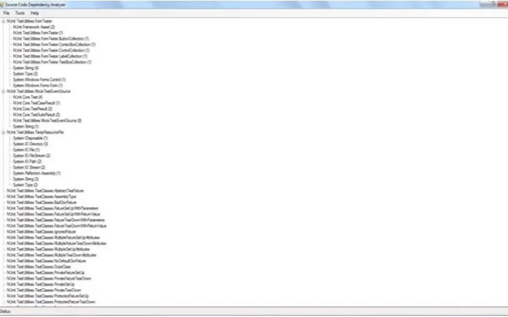
•To identify the associations of the affected component. To configure the component in the most effective manner, the developed Analyzer, SCDA, first parses the assemblies existing in the system, then shows the assemblies dependent on each other in two manners:
•Files dependent on other files •Files used by other files
[image:3.595.111.482.502.733.2]The developed Analyzer saves the dependency report in XML files. Dependencies, in tree type structure, are shown as in Figure 3. Metrics like Number of Classes and Number of total Dependencies can be calculated. While working with associations, Coupling and cohesion are the two terms which can’t be left behind. Coupling defines the dependence of one software component on other while cohesion is independence of one component from the other. In the other words, coupling and cohesion are contrary to each other. As the number of dependencies increases, coupling increases and cohesion decreases. It is expected that there should be less coupling and high cohesion. As coupling is less, it means that if we try to update the system, it will have very minimal harmful effect on the normal functioning of the system. The output given by the analyzer during phase 1 becomes the input of phase 2 of the framework1. The output of phase 1 is depicted in Figure 3.
CASE STUDY
In phase 2 of the framework, multiple versions of same component are considered for comparison. For this purpose, an open source software namely JSON.net [18] is considered. In order to evaluate the evolution in open source software, 50 versions of the software from www.codeproject.com, an online repository of open source software, are selected. From comparative analysis of the various versions of the software, following are the metrics which are suggested for the quantitative analysis of open software:
•LOC: It defines the total Lines of Code in the software.
• Number of Dependencies: It defines how many assemblies are dependent on other assemblies.
• Number of Classes: This number specifies the total number of classes defined in the source code of a particular version.
• Number of Methods: It specifies the total number of methods defined in the source code of a particular version.
• Percentage Change in LOC (P_LOC): It depicts the changes in LOC in percentage terms not in absolute manner.
• Percentage Change in Dependencies (P_DEP): It depicts the changes in No. of dependencies across various versions in percentage terms not in absolute manner.
• Percentage Change in number of classes (P_CLS): It depicts the changes in No. of dependencies across various versions in percentage terms not in absolute manner.
•Percentage Change in the Number of Methods (P_MET): It depicts the changes in No. of methods across various versions in percentage terms not in absolute manner.
• Overall Variation in the system (VAR): This factor specifies the overall change in the system.
• Percentage Overall Variation (P_VAR): This factor specifies the overall change in the system in percentage manner.
•Average percentage churn (A_P_VAR): This factor specifies the average overall change in the system in percentage manner.
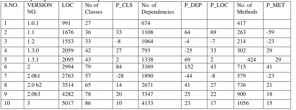
In this paper, it is not possible to demonstrate the full data set, therefore we are including a part of the complete data set to demonstrate the results of phase2 as shown in table 1with the help of following proposed metrics:
1. P_LOC:P_LOC can be defined as percentage change in LOC. Following formula is used to compute it.
𝑃𝑃𝐿𝐿𝐿𝐿𝐿𝐿 =(𝑋𝑋2𝑋𝑋− 𝑋𝑋2 1)× 100
{Where X1 & X2 are LOC values of two successive versions}
2. P_DEP: P_DEP can be defined as percentage change in the number of dependencies. Following formula is used to compute it.
𝑃𝑃𝐷𝐷𝐷𝐷𝑃𝑃 =(𝑋𝑋2𝑋𝑋− 𝑋𝑋2 1)× 100
{Where X1 & X2 are number of dependencies values of two successive versions}
3. P_CLS: It can be defined as percentage change in the number of classes. Following formula is used to compute it.
𝑃𝑃
𝐿𝐿𝐿𝐿𝐶𝐶=
(
𝑋𝑋
2
𝑋𝑋
− 𝑋𝑋
2
1)
× 100
{Where X1 & X2 are number of classes values of two successive versions}
4. P_MET: It can be defined as percentage change in the number of methods. Following formula is used to compute it.
𝑃𝑃
𝑀𝑀𝐷𝐷𝑀𝑀=
(
𝑋𝑋
2
𝑋𝑋
− 𝑋𝑋
2
1)
× 100
{Where X1 & X2 are number of methods values of two successive versions}
5. VAR: If X1 and Xn are the two extreme values of every parameter, then the formulae to compute VAR is:
𝑉𝑉𝑉𝑉𝑉𝑉
=
𝑋𝑋𝑋𝑋 − 𝑋𝑋
1
6. P_VAR: Percentage Overall change can be calculated as
𝑃𝑃
𝑉𝑉𝑉𝑉𝑉𝑉=
(
𝑋𝑋𝑋𝑋 − 𝑋𝑋
𝑋𝑋𝑋𝑋
1)
× 100
7. A_P_VAR: Average percentage Overall Change can be calculated as:
𝑉𝑉
𝑃𝑃𝑉𝑉𝑉𝑉𝑉𝑉=
𝑃𝑃𝑉𝑉𝑉𝑉𝑉𝑉 [image:4.595.29.536.592.781.2]𝑁𝑁 :
Table 1: depicting the values of various parameters for first ten versions. S.NO. VERSION
NO.
LOC No of Classes
P_CLS No. of Dependencies
P_DEP P_LOC No. of Methods
P_MET
1 1.0.1 991 27 674 417
2 1.1 1676 36 33 1108 64 69 263 -59
3 1.2 1553 33 -8 1064 -4 -7 214 -23
4 1.3.0 2059 42 27 793 -25 33 302 29
5 1.3.1 2095 43 2 1338 69 2 424 29
6 2 2994 79 84 3369 152 43 715 41
7 2.0b1 2763 57 -28 1890 -44 -8 579 -23
8 2.0 b2 3514 65 14 2671 41 27 736 21
9 2.0b3 4282 78 20 3347 25 22 900 18
Overall Variation in the system (VAR)
12258 77000 13470 1461
%age overall variation(P_VAR)
1236 2852 1999 124
Average %age variation( A_P_VAR)
22 53 37 2
OBSERVATIONS & INTERPRETATIONS
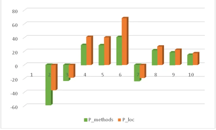
The graph in Figure 4 & 5 shows the relationship between all the four parameters i.e. P_DEP, P_LOC, P_CLS, P_MET. When the comparison is performed between the values of parameters listed above across the various versions, these are the few points which need further discussion.
• With the rise in change in LOC, there is consistent change in dependencies (as shown in Table 1 w.r.t. each successive version in ascending order). It means as the length of the source code increases, correspondingly number of dependencies also rises. It is believed that with the rise in LOC value, the unstructured code also increases, which results in higher coupling levels. This also means that this type of tightly coupled systems cannot be used for reusability.
• With the drop in change in LOC, there is consistent change in dependencies (as shown in Table 1 w.r.t. each successive version in descending order). It means that as the source code is removed for some reason, correspondingly level of dependencies decrease too. This scenario again doesn’t favor much for component-ware because of tightly coupled system.
• In few cases, there are some inconsistencies in the changes. For example, there is a significant change in
dependencies but corresponding change in LOC is not visible (For example, in Table 1, when we move from version 1.3.0 to version 1.3.1, change in LOC is 36 whereas change in dependencies is 545). In such cases, it is possible that some source code is added/removed/modified keeping the level of LOC stable but results in the change of dependencies. We suspect that code is replaced with structured code which results in loose coupling thereby can enhance the reusability level of said component-ware.
• When we study total 50 versions, One exceptional case is worth noticing, in which change in number of classes is massive whereas change in LOC & dependencies is very nominal. It can be illuminated that code is restructuring which may result in more organized structure because of rise in the number of classes (as shown in Table 2). When we move from version 6.0r5 to version 6.0r6, change in classes is 689 whereas change in dependencies is 693 and change in LOC is 132 which is very nominal as compare to other cases. • While considering the case of methods and LOC,
(except the case version 1.0.1 and version 1.1) there is a direct relationship between Number of Methods and LOC. It indicates that code is reasonably structured and cohesive.
Fig5: graph depicting the relationship between P_methods and P_loc.
Table 2: depicting the values of various parameters for different versions.
S.NO VERSI ON NO.
LOC No of Classes
P_C LS
No. of Dependenci es
P_D EP
P_L OC
No. of Met hods
P_ME T
Observations
1 1.0.1 991 27 674 417 Increase in Loc, no. of
dependencies increases too
2 1.1 1676 36 33 1108 64 69 263 -59
3 4.0r3 1824 6
390 3 7120 5 5 3726 5 Decrease in LOC, no. of dependencies decreases too 4 4.0r4 8865 180 -54 3680 -48 -51 2025 -84
5 1.3.0 2059 42 27 793 -25 33 302 29 significant change in dependencies but corresponding change in LOC is not visible
6 1.3.1 2095 43 2 1338 69 2 424 29
7 6.0r5 1278 3
75 -90 12868 1 1 2584 0 Change in number of classes is massive whereas change in LOC &
dependencies is very nominal.
8 6.0r6 1291 5
764 919 13561 5 1 2596 0
CONCLUSION
In this paper, an effort is made to study the quantitative analysis of the evolution of open source software using software metrics. As the evolution proceeds, dependency management in configuring the component based systems is the key issue. A framework (SCDA) has already been proposed in our earlier publication [11]. In this paper, a case study is performed by taking the source code of open source software using the framework. The output of SCDA is useful in studying the evolution of components over multiple versions. It helps in studying the behavior of the system over time.
REFERENCES
[1] Parnas. D.L., 1994. Software aging. In Proc. of the 16th Intl. Conf. on Software Engineering (ICSE-16), Sorrento, Italy, May 1994
[2] Kumar, V., A. Sharma, R. Kumar and P.S. Grover, 2012. Quality aspects for component-based systems: A metrics based approach. Software Practice Experience, 42: 1531– 1548. doi:10.1002/spe.1153
[3] Larsson, M., 2000. Applying configuration management techniques to component-based systems, Licentiate Thesis Dissertation 2000-007, Department of Information Technology, Uppsala University.
[4] Clements, P.C., 2001. "From Subroutines to Subsystems: Component-Based Software Development." In Councill, WT, Heineman, GT, (eds.): Component-Based Software Engineering: Putting the Pieces Together. Addison Wesley, 2001.
[5] Hutchinson, J., and G. Kotonya, 2006. A Review of Negotiation Techniques in Component Based Software Engineering. In Software Engineering and Advanced Applications, 2006. SEAA'06. 32nd EUROMICRO Conference on (pp. 152-159). IEEE.
[7] Sangal N., E. Jordan, V. Sinha and D. Jackson, 2005. Using dependency models to manage complex software architecture. In: Proceedings of the 20th annual ACM SIGPLAN conference on object oriented programming, systems, languages, and applications, San Diego
[8] Sullivan K., Y. Cai, B. Hallen and W. Griswold, 2001. The Structure and Value of Modularity in Software Design, Proceedings of the 8th European Software Engineering Conference held jointly with 9th ACM SIGSOFT International Symposium on Foundations of Software Engineering, 2001
[9] Available from http://www.dependencywalker.com [Accessed 2 March 2017].
[10] McIlroy, M., 1969. Mass produced software components: Software engineering concepts and techniques. In Proceedings of NATO Conference on Software Engineering, pp: 88–98. [11] Ratti, N. and P. Kaur, 2016. Conceptual Framework for
Analyzing the Source Code Dependencies, Advances in Intelligent Syst., Computing, Vol. 554, Sanjiv K. Bhatia et al. (Eds): Advances in Computer and Computational Sciences, 978-981-10-3772-6, 430542_1_En, (33)[ under publication] [12] Brown, A.W. and K.C. Wallnau, 1996. Engineering of
component-based systems, In Proceedings of the 2ndInt. Conference on Engineering of Complex Computer Systems, Montreal, Canada, Oct 1996.
[13] Rakic, M. and Medvidovic N., 2001. Increasing the confidence in off-the-shelf components: A software connector-based approach. ACM SIGSOFT Software Engineering Notes, 26(3), pp: 11-18.
[14] SHAW M., 1995. Architectural issues in software reuse: It's not just the functionality, it's the packaging. Symposium on Software Reusability, Seattle, Washington, USA, April, pp: 3-6.
[15] Cheesman, J. and J. Daniels, 2001. UML Components, a Simple Process for Specifying Component-Based Software, Addison-Wesley, 2001.
[16] Szyperski, C., Gruntz, D. and S. Murer, 2008. Component Software: Beyond Object-Oriented Programming, Addison-Wesley Professional, Boston, First Edition 1997. ISBN 0-201-17888-5.
[17] Belguidoum, M. and F. Dagnat, 2007. Dependency management in software component deployment, Electronic Notes in Theoretical Computational Sciences 182: 17–32. [18] Available from https://json.codeplex.com/[Accessed 2 March
2017].
![Fig. Architecture [15]](https://thumb-us.123doks.com/thumbv2/123dok_us/685868.1075965/2.595.40.540.193.343/fig-architecture.webp)