Volume 3, No. 1, Jan-Feb 2012
International Journal of Advanced Research in Computer Science
RESEARCH PAPER
Available Online at www.ijarcs.info
ISSN No. 0976-5697
Implementation of Space Time Trellis Code Using Rayleigh Fading Scenario
Sujeet Singh Bhadouria* M.Tech,IT(IVsem) L.N.C.T. Bhopal (M.P), India [email protected]
Dr.Manish Shrivastava H.O.D.(I.T.)
L.N.C.T. Bhopal (M.P), India [email protected]
Vineet Richcharia H.O.D(.C.Sc.) L.N.C.T. Bhopal (M.P), India
Abstract:In this paper we implement space time trellis code using relay fading scenario. We present here the design of the 4psk with 2 transmit antennas and 1,2 receiver antennas at 4,8,16& 32 state. In this paper we constructed 4-psk sttc code using rank, determinant and euclidean distance criterion over rayleigh fading scenario.
Keywords:space-time trellis code; multiple transmit antenna, multiple receiver antenna; diversity; wireless communication; fading; s\n ratio;
I. INTRODUCTION
All A typical S'ITC based wireless system has an encoder, pulse shaper, modulator and multiple transmit antennas at the transmitter, and the receiver has one or more receive antennas, demodulator, channel estimator and STTC decoder. We
consider a mobile communication system with
n
t transmitantennas and
n
rreceive antennas as shown in Figures 1 (a) and(b). The space-time trellis encoder encodes the data
s t
( )
coming from the information source and the encoded data isdivided into
n
t streams of data1 2
...
ntt t t
c
c
c
. Each of these streams of data passes through a pulse shaper before being modulated. The output of modulator
i
at time slott
isthe signal
i t
c
, which transmitted through is transmit antenna
i
.Here
n
t1
i
n
t.The transmitted symbols have energy
E
t. We assume thatthe
n
t signals are transmitted simultaneously from theantennas. The signals have transmission period T. In the
receiver, each antenna receives a superposition of
n
ttransmitted signals corrupted by noise and multipath fading. Let the complex channel coefficient between transmit antenna i
and receive antenna j have a value of
h
i j,( )
t
at timet
,where
1
i
n
r.The received signal at antenna
j j
,
1, 2,...,
n
r G.L.Stuber [1] is then
, 1
=
( ) ( )
n
i j
t s i j t t
i
r
E
h
t c t
(1.1)
Where
j
t is additive white Gaussian noise (AWGN) at
receive antenna
j
, which has zero mean and power spectraldensity
N
0 andh
i j,( )
t
channel coefficient between transmit and receive antennas J. Yuan, Chen and B. Vucetic [11].
II. CODECONSTRUCTIONOF4-PSK STTC
A signal constellation diagram for 4-PSK is shown in Figure 2. With PSK information is contained in the signal phase. For 4-PSK, the phase takes one of four equally spaced
values, such as
0,
2
,
4
, and
6
4
4
4
. These are typicallyrepresented by a Gray code S. Haykin [10] and B. Sklar [9], as shown on the right side of Figure 2. These signal points are also labeled as 0, 1, 2 and 3. We can also express these in complex notation
The encoder structure of a 4-state 4-PSK STTC is shown in Figure 3 (a), with bits input to the upper and lower branches. The memory orders of the upper and lower branches are
1
and
2 respectively. These are basically shift registers.The main purpose of the shift registers in the encoder is to store the previous transmitted bits. The length of the shift register is the memory of the encoder. The branch coefficients are
arranged alternatively in the generator matrix, with
a
irepresenting the most significant bit (MSB).
The input bit streams
1 2
and
t t
I
I
are fed into the branches
of the encoder with
1
t
I
being the MSB. The output of the encoder is Z. Chen, J. Yuan, B. Vucetic[19], V. Tarokh, N. Seshadri, A. R. Calderbank [6]
1 2
1 2
0 0
.
.
mod 4
1, 2,
v v
k k k
t t p p t q t q
p q
x
I
a
I
b
k
(1.2)
where
v
1v
2v
and the number of states is2
v.v
i iscalculated as
1
,
1, 2
2
iv i
v
i
(1.3)
Here
x
denotes the largest integer smaller than or equal tox
. For each branch, the output is the sum of the current input scaled by a coefficient and the previous input scaled by another coefficient. The two streams of input bits are passed through their respective shift register branches and multiplied by thecoefficient pairs
1 2 1 2
(
a
p,
a
p) and ( ,
b
qb
q)
. Here,1 2
,
0,1, 2,3 ,
1, 2,
0,1,...., ,
0,1,...., .
k k p q
a b
k
p
v q
v
Figure 2. 4-PSK signal constellation diagram
(a)
(b)
Figure 3 4 PSK 4 state STTC (a) Trellis Diagram (b) Encoder Structure
Then
1 2
and
t t
x
x
are transmitted simultaneous through the first and second transmit antennas, respectively. Figures 4 (a) and (b) shows 8 state and 16 state trellis diagrams respectively, for a rate of 2 b/s/Hz N. Seshadri, V. Tarokh, A.R. Calderbank [3].
III. PERFORMANCECRITERIA
We assume that the STTC codeword is given by
1 2 1 2 1 2 erroneous code word e , given by
1 2 1 2 1 2 between the erroneous codeword and the transmitted codeword as follows –
IV. DESIGNCRITERIAFORSTTCOVERRAYLEIGH FADING
A. Rank Criterion:
The rank criterion optimizes the spatial diversity gain achieved by a STTC. Assume B(c,e) has minimum rank
r
over the set of pairs of distinct codewords so a diversity of.
rr n
is acheved V. Tarokh, N. Seshadri, A. R. Calderbank [6], Z. Chen, J. Yuan, B. Vucetic [8]. To illustrate this criterion N. Yuen [5], consider a CPSK system where the transmitted codeword is c = 220313, and the erroneous codeword the receiver decides upon is e = 330122. Figure 2 gives the 4PSK
signal constellation. In this example,
n
t= 2 and the messageantenna, the diversity gain is 2.
B. Determinant Criterion:
The determinant criterion optimizes the coding gain. Recall that
r
is the rank ofA c e
( , )
. Coding gain corresponds to the example, for the rank criterion the eigenvalues of the matrix A are example is 4.9327 N. Yuen [31].C. Euclidean distance Criterion:
When the diversity gain is large (with two or more receive antennas), Chen, B. Vucetic, J. Yuan and Lo. Ka. Leong [2] proposes another design criterion, namely the Euclidean Distance Criteria (EDC). According to Chen, B. Vucetic, J. Yuan and Lo. Ka. Leong [2], the Rank and Determinant criteria (RDC) applies to the systems with a single receive antenna and a small number of transmit antennas. This shows that with
diversity gain
rn
r4
S. M. Alamouti [12] shows that theerror probability is upper bounded by
1 1
When
rn
r4
, Which indicates that we should maximizethe minimum squared Euclidean distance between any two different codewords Chen, B. Vucetic, J. Yuan and Lo. Ka. Leong [2] .
V. SIMULATIONSYSTEMMODEL
Figure 5. Simulation system model
Random M-PSK symbols are grouped into frames, which consists of 130 symbols each. The space-time encoder takes the frame as input and generates codeword pairs for each input carried out. Channels used in this project include flat Rayleigh fading channels and two-ray model frequency selective fading channel.
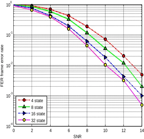
Figure 6. 4psk, 2 transmitter, 1 receiver
0 2 4 6 8 10 12 14
Figure 7. 4psk, 2 transmitters, 2 receiver
VII.CONCLUSION
In this paper ,an efficient method to design the best 4-psk STTCs with two transmit antennas and 1,2 receiver antennas has been presented.we find that when we increase the receiver antennas .we get more coding gain .it increase 4to32states.we find higher coding gain at 2 receiver antennas at 32 state. We also get less s\n ratio.
VIII.REFERENCES
[2] J. Lai and N. B. Mandayam, “Performance of turbo coded WCDMA with downlink space-time block coding in correlated fading channels," accepted for publication in IEEE transaction on wireless communications,2002.
[3] N. Seshadri, V. Tarokh, A.R. Calderbank," Space-time codes for wireless communication: code construction," IEEE 47th Vehic. Tech.. Conf. Tech.., pp. 637-641, 1997.
[4] Z. Chen, J. Yuan, B. Vucetic, "Improved space-time trellis coded modulation scheme on slow Rayleigh fading channels," Ehctronics Lett., vo1.37, pp.440-441,29 Mar. 2001
[5] N. Yuen, " Performance Analysis of Space-time Trellis codes," Master of Engineering report, University of British Columbia, April 2000
[6] V. Tarokh, N. Seshadri, A. R. Calderbank, "Space-time codes for high data rate wireless communication: performance criterion and code construction," IEEE Trans. Innfom. Theoy, vol.44, pp. 744-65, Mar. 1998.
[7] G. Foschini, “Layered space-time architecture for wireless communication in a fading environment when using
multi-element antennas," in Bell Labs Technical Journal, 1996, pp. 41-59.
[8] Z. Chen, J. Yuan, B. Vucetic, "Improved space-time trellis coded modulation scheme on slow Rayleigh fading channels," Ehctronics Lett., vo1.37, pp.440-441,29 Mar. 2001.
[9] H. Shah, A. Hedayat, and A. Nosratinia, “Performance of concatenated channel codes and orthogonal space-time block codes," submitted to IEEE Transactions on Wireless Communications, 2003.
[10] S. Haykin, Communication Systems. Delhi, India, John Wily and Sons, 4& edition, 2001
[11] J. Yuan, 2. Chen and B. Vucetic, " Performance of space-time c o h g on fading channels," IEEE Trans. Commn , vol. 51, no. 12, pp. 1991-1996, Dec. 2003.
[12]S. M. Alamouti, “A simple transmit diversity technique for wireless communications,” IEEE J. Select. Areas Commun., vol. 16, no. 8, pp. 1451-1458, October 1998.