DOI: http://dx.doi.org/10.26483/ijarcs.v8i7.4228
Volume 8, No. 7, July – August 2017
International Journal of Advanced Research in Computer Science
RESEARCH PAPER
Available Online at www.ijarcs.info
ISSN No. 0976-5697
PERFORMANCE EVALUATION OF DECISION FEEDBACK EQUALIZATION
(DFE) BASED DISPERSION COMPENSATOR BY VARYING FORWARD TAP
SPACE & ADAPTIVE STEP SIZE IN THE SCENARIO OF 4X10-GBIT/S WDM
SYSTEM
Gursharanpal Singh
Department of ElectronicsTechnology Guru Nanak Dev University
Amritsar, India-143005
Shivinder Devra
Department of ElectronicsTechnology Guru Nanak Dev University
Amritsar, India-143005
Karamdeep Singh
Department of ElectronicsTechnology Guru Nanak Dev University
Amritsar, India-143005
Abstract: With the advancement of technology, demand of bandwidth increases exponentially with time. Hence, optical fiber communication become the optimum choice for backbone networks. As efficiency of optical system is limited by congenital parameters such as chromatic dispersion. So, in this work, we have evaluated the ability of electronic equalization scheme reduce the CD (chromatic dispersion for an optical communication system capable of transporting 4 channels at 10 Gbps line rate over a distance of 30km. Further, we compare the performance of decision feedback equalizer with two different configurations.
Keywords: Dispersion compensation, Electronic equalization, Feed Forward Equalizer (FFE) Decision Feedback Equalizer (DFE), Chromatic Dispersion.
I. INTRODUCTION
In fiber optics communication information is transmitted in the form of pulse from transmitter to receiver through optical fiber. The pulse is an electromagnetic carrier that is modulated to carry information. Potential bandwidth of optical communication is first hand advantage over other communication system [1]. Run-time issues of optical communication are identical to other systems for instance dispersion, attenuation and non-linear effects that limit its performance. Out of these, dispersion is the main reason for the deterioration of signal. Though it is vital to invent efficient distortion reduction technique that boost the performance of optical communication. Dispersion compensation fiber (DCF) can be employed to eliminate the effects of dispersion. But it is hulking, and have large insertion loss. Whereas, Electronic Dispersion compensation provide better solution to this problem, having low insertion loss, low power consumption and compact size. Electronic dispersion compensation (EDC) is used to eliminate chromatic dispersion for 10-Gbit/s transmission. Thus, reduces system capital loss by eliminating optical dispersion compensators and amplifiers. It also enables dynamic and remote network configuration, thus ease the deployment and operation of system. The remainder of paper is organized as follows: In section 2, overview of chromatic dispersion is discussed. In section 3, the aspects previous survey is discussed. In section 4, technique used to reduce the dispersion is explained. In section5, system setup is enlightened. In section 6 results collected are discussed and conclusion is made in section 7.
II. CHROMATIC DISPERSION
Pulse spreading in optical fiber is termed as dispersion. As different wavelengths of light propagate at different velocities through the fiber because of dependence of refractive index is a wavelength dependent parameter, this phenomenon is called chromatic dispersion. At high speed data transmission in optical system, dependence of refractive index on intensity of signal, another non-linearity i.e. Kerr effect become active [2].
III. LITERATURE SURVEY
As optical fiber provides high bandwidth transmission, it become optimum choice for backbone networks and is rapidly encroaching customer premises, enterprise networks, as well as backplane and storage area networks [1]. At high bandwidth performance of optical fiber link is limited by noise factor, ISI (Intersymbol interference) or dispersion, etc.
In 1990s, research started on application of various distortion equalization techniques, out of which Electronic dispersion compensation (EDC) technique provide effective results for high bandwidth.
J. Winter et. al. (1990), demonstrated for the first time the use of electronic equalizers for high speed operation in research labs [2]. Later research approved that efficiency of equalizer is decreased more due to signal dependent noise than white Gaussian noise in wireless transmission system [3], [4].
digital signal processing introduced in 10-Gbit/s optical transmission.
J. Poirrier et. al. (2004), suggested the idea of equalization in Analog to Digital Convertor along with massive DSP and complex optical field processing in electric domain [5]. M. G. Taylor et. al. (2004), suggested the used of Dynamic EDC in the receiver for very quickly adaptation of un-forecasted CD changes. Based on the implementation design, significant gain in chromatic dispersion limited reach can be expected with receiver EDC [6].
T. Beukema et. al. (2005), proposed DFE design circuit for high-speed decision-feedback settling. This design can be utilized at 6.4-Gbit/s and beyond. Hence, it is compatible to high-speed CMOS processing cores used in modern switch, computers and routers [7].
In 2009, design of feed forward equalizer for communication system is introduced that contain tapped filter with multiple filter multipliers, a correlator with multiple correlator multipliers, and shared delay elements connected to filter multipliers and correlator multipliers. Each delay stage may include multiple delay stages that can be interconnected in array.
S. Porto et. al. (2013),introduce adaptive Electronics Dispersion Compensation, in which EDC taps can be adapted using less 500 training bits with simple LMS algorithm. This reduces the size of overhead thus maximize the efficiency [8].
P. Ossieur et. al. (2014), introduce burst-mode electronic dispersion compensation, it is used to sustain the upstream channels of hybrid DWDM-TDMA PONs. Fast tap adaptation are made feasible with small training sequence fixed in preamble of each TDMA burst [9].
Through high speed communication are limited by chromatic dispersion. EDC can be implemented through various approaches such as mixed spaced FFE/DFE using submicron CMOS technology or by employing DSP based equalizer chips etc. Direct detection DFE use simple circuitry and consume low power (approx. 1W). On the hand, DSP based equalizer chip deliver better result but they required complex though costly circuit and required high power. Cost and power consumption are the major aspect of access applications. In this work, we select direct detection DFE based EDC and analyze its performance over 10-Gbit/s.
IV. DISPERSION COMPENSATION
Fiber optic communication affected by the chromatic dispersion within the fiber. Due to this bit symbols get broadens and distort, hence make it difficult to decode the signal. Usually distortion is removed in optic domain only
i.e. before photo-detection. Whereas in Electronic Dispersion compensation, electronics is utilized for this purpose. There are two different methodology to implement EDC as follow:
A. Direct detection
It is used in receiver, in this method efficiency depend on frequency dependent phase change information. This method generally depends on tapped delay line equalizers, where input signal is sliced and transferred over different time delays and recombined after amplification [10]. The non-linear equalization technique such as decision feedback equalizer (DFE) have decision thresholds that depend on previous data, which is used to reinforce the lost spectral information.
B. Optical-heterodyne detection
It is used in receiver, have high efficiency for electronic dispersion compensation because phase information is preserved. To remove chromatic dispersion effectively we need an electronic filter with suitable frequency response used at intermediate frequency [11].
In this work, two different configuration of decision feedback equalization using direct detection are presented and their performance were analyzed in terms of quality factor at different frequencies, step size, forward tap spaces, etc. to get optimum result.
V. SYSTEM SETUP
Figure 1: Simulation setup
VI. RESULTS AND DISCUSSION
For performance analysis purposes Quality factor (Q-factor) has been adopted as performance metric which is defined in equation No. (1) as follows [12-18]:
(1)
The performance analysis of DFE has been performed in two configurations:1) 4 forward taps and 2 feedback tap and 2) 9 forward taps and 3 feedback taps:
A. Case 1: Equalizer (4,2) [4 forward and 2 feedback
taps]:
[image:3.595.343.528.505.670.2]First, the performance of the EDC (4,2) was analyzed in system. Different tap coefficients are used to train the DFE, fig 2 shows the Q factor obtained for respective test-sets of tap coefficient. Coefficient that deliver max Q factor were selected.
Figure 2: Q factor of different test sets for coefficient of equalizer (4,2)
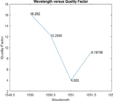
This configuration is simulated over 4-channel WDM, starting from 1550 nm with wavelength spacing 0.5 nm, it gives max. Q factor of 16.252 for 1550 nm at first channel as shown in fig 3.
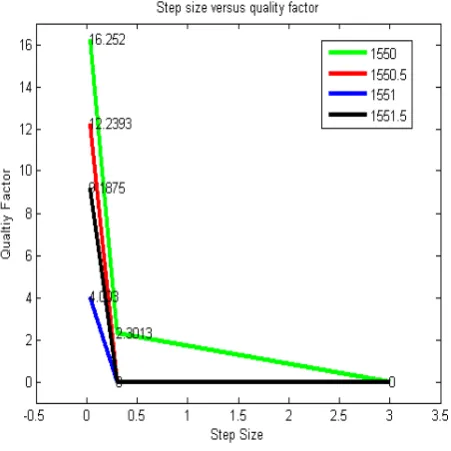
[image:3.595.50.257.543.770.2]Figure 4: Step size vs Q factor equalizer (4,2) Next, equalizer is analyzed for different forward tap spaces. Fig 5 shows the performanceof equalizer for tap spaces ranging from 5 to 10.
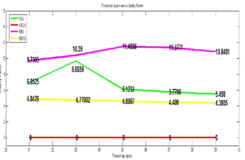
Figure 5: Forward tap space vs Q factor of equalizer (4,2) The results clearly demonstrated that equalizer with 4 forward taps and 2 feedback taps give its best performance at 1550 nm wavelength, with step size 0.03, leakage factor of 1, and forward tap space of 9. It gives maximum Q factor of 16.252 after training.
A. Case 2: Equalizer (9,2) [9 forward taps and 3 feedback
taps]
Similar procedure was followed to get the forward and feedback taps coefficients for this configuration. This filter is also tested in same environment. For the instance, we select only real values for taps. Fig 6 shows the performance of equalizer for different tap coefficients.
Figure 6: Q factor of different test sets for coefficient of Equalizer (9,3)
[image:4.595.46.284.345.547.2]The performance of this configuration is analyzed over 4-channel WDM, starting from 1550 nm with wavelength spacing 0.5 nm. Fig 7 shows that it gives max Q factor on third channel at wavelength of 1551 nm.
[image:4.595.339.545.557.746.2]Next, this equalizer is tested for different forward tap spaces. Fig 9 shows its performance for tap spaces ranging from 31 to 39.
Figure 9: Forward tap space vs Q factor of Equalizer (9,3) The result clearly demonstrates that equalizer with 9 forward taps and 3 feedback taps give its best performance at 1551 nm wavelength, with step size 0.03, leakage factor of 1, and forward tap space of 35. It gives maximum Q factor of 11.7475 after training. Though forward tap space of 33 give better result for all channels collectively.
VII. CONCLUSION
In this paper, performance of electronics dispersion compensation technique has beenanalyzed for two configurations of DFE for different parameters. Both configurations were inspected over 4-Channel 10-Gbit/s WDM system over 30 km distance employing standard SMFs. It has been observed that equalizer having 4 forward taps and 2 feedback taps give better performance with max Q factor of 16.252 than equalizer with 9 forward taps and 3 feedback taps having max. Q factor of 11. 7475.It has been learnt that equalizer with “4 forward & 2 feedback tap” adapt fastest than “9-forward & 3-feedback tap”, hence required small training sequence. MLSE and link based timing distribution system in EDC can be further applied to improve the performance.
REFERENCES
[1] Singer, A. C., et al., 2008, "Electronic dispersion compensation," IEEE Signal Processing Magazine, 25(6), pp. 110-130.
[2] Winters, J. H., et al., 1990 "Electrical signal processing techniques in long-haul fiber-optic systems," IEEE Transactions on Communications, 38(9), pp. 1439-1453.
[3] Moller, L., et al., 1999, "ISI mitigation using decision feedback loop demonstrated with PMD distorted 10 Gbit/s signals." Electronics Letters, 35(24), pp. 2092-2093.
[4] Bülow, H., et al., 2000 "PMD mitigation at 10 Gbit/s using linear and nonlinear integrated electronic equalizer circuits." Electronics Letters 36(2), pp. 163-164.
[5] Poirrier, Julien, et al., 2000, "Experimental nonlinear cancellation of polarization-mode dispersion." Optical Fiber Communication Conference, 3, pp. 119-121.
[6] Taylor, Michael G., 2004, "Coherent detection method using DSP for demodulation of signal and subsequent equalization of propagation impairments." IEEE Photonics Technology Letters, 16(2), pp. 674-676.
[7] Beukema, Troy, et al., 2005, "A 6.4-Gb/s CMOS SerDes core with feed-forward and decision-feedback equalization." IEEE Journal of Solid-State Circuits, 40(12) pp. 2633-2645. [8] Porto, S. et al., 2013, "Requirements for adaptive electronic
dispersion compensation in burst-mode systems." Optical Fiber Communication Conference. Optical Society of America, pp. OTh3B-5.
[9] Ossieur, P. et al., 2014 "Burst-mode electronic dispersion compensation." Optical Fiber Communications Conference and Exhibition (OFC), (2014), pp. 1-3.
[10] Cartledge, J. C., et al., 1992, "Performance of smart lightwave receivers with linear equalization." Journal of lightwave technology, 10(8), pp. 1105-1109.
[11] Yu, Q.et al., 2006, "Electronic data processing for error and dispersion compensation." Journal of lightwave technology, 24(12), pp. 4514-4525.
[12] Singh, K., & Kaur, G., 2015, “Interferometric architectures based all-optical logic design methods and their implementations.” Optics & Laser Technology, 69, pp. 122-132.
[13] Singh, K.et al., 2015, "A single As 2 Se 3 chalcogenide Highly Non-Linear Fiber (HNLF) based simultaneous all-optical half-adder and half-subtracter." Optical Fiber Technology 24, pp. 56-63.
[14] Singh, K.et al., 2016, "Simultaneous all-optical half-adder, half-subtracter, comparator, and decoder based on nonlinear effects harnessing in highly nonlinear fibers." Optical Engineering, 55(7), pp. 077104-077104.
[15] Singh, K., & Kaur, G., 2014, "All-optical half adder and half subtractor based on semiconductor optical amplifier.” Open Journal of. Communication & Software 1.1, pp. 42-51. [16] Singh, K.et al., 2016, "A cascadable all-optical half-subtracter
based on cross-modulation effects in a single highly nonlinear fiber (HNLF)." Optical and Quantum Electronics, 48(9), pp. 418.
[17] Singh, K.et al., 2016, "Enhanced performance of all-optical half-subtracter based on cross-gain modulation (XGM) in semiconductor optical amplifier (SOA) by accelerating its gain recovery dynamics." Photonic Network Communications. 1-20.