DOI: 10.15662/ijareeie.2014.0307037
Performance Analysis of Different PSK
Modulation Schemes for 2X2 MIMO System
Using Microstrip Antennas
Harshal Nigam1, Mithilesh Kumar2
PG Student [DC], Department of Electronics Engineering, UCE, RTU, Kota, Rajasthan, India 1 Professor, Department of Electronics Engineering, UCE, RTU, Kota, Rajasthan, India 2
ABSTRACT: MIMO techniques promise a significant boost in the capacity of wireless systems. In this paper, MIMO system is designed using a compact double-sided printed antenna having ultra-wideband and band-notched characteristic. The UWB antennas are designed on CST Microwave studio simulation software with return loss less than -10dB, and further using the results from CST, performance analysis of different PSK modulation schemes including BPSK, QPSK, 8 PSK and 16 PSK is done on MATLAB software. The MIMO UWB antennas are designed using polarization diversity of the individual antennas. The transmitting bandwidth is UWB (i.e. 3.1-10.6GHz) and the receiving bandwidth is notch UWB (notch bandwidth 5-5.9GHz) are chosen to reduce the interference at the receiver side. The MIMO UWB system is designed for frequency of 9-10 GHz that is used for micro power radar application in the ultra wideband removing the interference from WLAN band.
KEYWORDS: Band-notched, Bit Error Rate (BER), Binary Phase Shift Keying (BPSK), Double-sided Printed, Multiple Input Multiple Output (MIMO), Quadrature Phase Shift Keying (QPSK).
I.INTRODUCTION
In wireless communications, spectrum is a scarce resource and hence imposes a high cost on the high data rate transmission. Fortunately, the emergence of multiple antenna system has opened another very resourceful dimension – space, for information transmission in the air. It has been demonstrated that multiple antenna system provides very promising gain in capacity without increasing the use of spectrum, reliability, throughput, power consumption and less sensitivity to fading, hence leading to a breakthrough in the data rate of wireless communication systems. Since then, multiple input multiple output (MIMO) system has become one of the major focuses in the research community of wireless communications and information theory as in [1].
The UWB antenna has its advantages in the areas of radar system, communication area and military applications. The Federal Communications Commission (FCC) has approved on the 3.1-10.6 GHz unlicensed band for UWB communication since 2002 which has overcast the band of WLAN (5.15- 5.825GHz) and may interfere with some communication systems as in [2]. So, if the band-notched frequency of WLAN can be produced, the interference could be avoided.
DOI: 10.15662/ijareeie.2014.0307037 between the elements of an antenna array. by increasing the distance between the antennas, the mutual coupling can be reduced. However, the distance between the antennas cannot be maintained too large, since MIMO systems have their major applications in Mobile terminals, laptops, MODEMs, WLAN Access Points etc., where miniaturization is the main concern. The distance between antenna elements in practice cannot be extended beyond a certain level which limits the use of spatial diversity to achieve the desired spectral efficiencies and transmission qualities. As an alternative solution to achieve compactness in MIMO systems, the use of pattern diversity as in [5, 6], multimode diversity as in [7], and polarization diversity techniques as in [8] in conjunction with space diversity are discussed in the literature. In the present design, the orthogonal polarization concept is applied to the proposed multi slot patch antenna yielding better results in terms of return loss and mutual coupling.
A brief review of different literature on the paper topic was done, as in [9] comparison of different PSK and FSK schemes is done for a practical communication system. The theoretical formula for different modulation schemes is also given. The work described in [10] the modulation schemes comparison is done for a MIMO system Rayleigh channel using space time codes. Performance analysis of MIMO space time block codes for different modulation schemes is also described in [11]. Thus, getting a brief idea from different literatures mentioned above and many more. In this paper we have done a comparison of different PSK modulation schemes but for a practical channel using practical channel matrix. The channel is created for a 2X2 MIMO system with practical antennas designed on CST Microwave studio and further after obtaining the channel matrix the modulation schemes comparison is done on MATLAB software.
This paper is organized as follows. In Section II, the design methodology and structure of a single UWB antenna along with a notch is described along with the simulation results. Section III incorporates the use of above antenna in a 2X2 MIMO system. Polarization diversity is applied to the above MIMO antennas and simulated results are analysed further. In Section IV the performance analysis of different M-PSK modulation techniques is done on the MIMO channel. Section V concludes the work done
II.UWB ANTENNA DESIGN
A. Antenna Design
The UWB antenna is designed on a substrate which is printed on both sides, on one side is the patch and other side is a partial ground plane. The patch is fed by a micro strip feed line, appropriate matching of the feed line is required to produce UWB characteristics of the antenna.
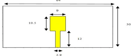
The notched bands are generated by conventional resonant structures, that is the slots or uniform half wavelength resonators, the spurious notched bands caused by spurious resonances would emerge and distort the antenna’s UWB performance. When exciting the slot mode, a strong resonance is provoked at 5.5 GHz, which alters the current distribution within the planar surface of the monopole, in turn translates into the band notch. The band-notched frequency produced by the unmatched impedance is 5.5GHz. The length of the slot is half wavelength of the notch frequency basically, the width of the notch band lies on the width of the slot and changing the length of the slot can cause the change on notch frequency. That is, the wider and longer the slot, the wider notch band and the higher notch frequency. The geometry of the given UWB antenna is illustrated in Fig. 1. It is fabricated on a 64X30 mm2 FR-4 substrate with a dielectric constant of 4.3 and a substrate thickness of 1.5 mm. The top and bottom patches printed on the substrate are the radiating structure and the ground plane.
DOI: 10.15662/ijareeie.2014.0307037 The back view is shown in Fig. 2. The top patch of the substrate has dimension of 9X10.5 mm2 which is fed by a strip line having a width of 2.9 mm. The bottom patch of substrate is just a partial ground plane which generates ultra wideband characteristics of the antenna.
Fig. 2 UWB antenna with dimension in mm (back view)
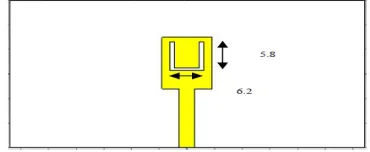
The band notched characteristics of the antenna are generated by cutting a U-slot on the upper patch as shown in Fig. 3. The dimensions of the slot are also shown in the same. The proposed antenna with and without U-shaped slot has been simulated by CST Microwave studio.
Fig. 3 UWB antenna having slot with dimension in mm
B. Simulation Results
The simulation results of the antenna are shown in Fig. 4, from the simulated graph it is observed that for UWB frequency range 3.1-10.6 GHz, S11<-10dB. Thus the results are in agreement that antenna operates on UWB.
Fig. 4 Simulated results for UWB antenna
The notched results are shown in Fig. 5, which shows that the WLAN frequency band 5.1-5.9GHz has been notched from the UWB antenna simulation curve of Fig. 4 it can be seen that the smallest attenuation that is S11=-23dB occurs
for a frequency of 9.4GHz, so we select this frequency. MIMO UWB system is designed at this frequency of 9.4GHz that is used for micro power radar application in the ultra wideband removing the interference from WLAN band.
DOI: 10.15662/ijareeie.2014.0307037
Fig. 5 Simulated results for the notched UWB design
III.MIMO SYSTEM DESIGN
A. MIMO Array
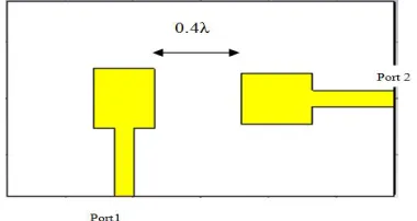
Consider, a 2X2 MIMO system having two antennas at the transmitter side and two at the receiver side. The main criteria for MIMO system design is mutual coupling, which mainly arises due to the smaller spacing between the two antennas, when multiple antennas are involved at closer spacing the design issues are more complicated. The mutual coupling mainly depends on the distance between the elements of an antenna array by increasing the distance between the elements of the antennas, the mutual coupling can be reduced. The mutual coupling can be mitigated more with the use of polarization diversity. The orthogonality of two distinct polarizations constructs independent and uncorrelated signals on each antenna. In the design of our system to achieve orthogonal polarization, one antenna is rotated to 900 with respect to its adjacent element as shown in the Fig. 6. The separation between the antennas is 12.8 mm which is
0.4λ. The antennas in the array have the same dimensions as mentioned in Section II. The antennas are mounted on a substrate symmetrically with εr = 4.3, which in turn is mounted on a ground plane.
Fig. 6 MIMO transmitting section having two antennas
B. Simulation Results of Array
The simulated results are shown in Fig. 7 and 8 for S11 and S22 respectively, we can see that S11 and S22 curves show that
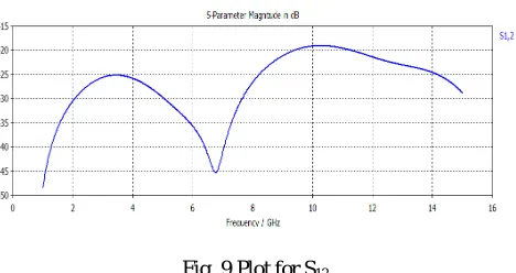
both antennas are operating in the UWB region independently, also the insertion loss S12 between the two antennas is
DOI: 10.15662/ijareeie.2014.0307037
Fig. 7 Plot for S11 showing UWB characteristic
Fig. 8 Plot for S22 showing UWB characteristic
Fig. 9 Plot for S12
We also calculate the correlation coefficient and diversity gain for the two antenna array. Correlation coefficient is given by (1)
= ⃒ ∗ ∗ ⃒
( ⃒ ⃒ ⃒ ⃒ ) ( ⃒ ⃒ ⃒ ⃒ )
(1)
Diversity gain is given by (2)
DG = 10∗ 1−(0.99∗ ρ) (2)
DOI: 10.15662/ijareeie.2014.0307037
C. MIMO System
We have designed the transmitting section, having two UWB antennas that are mutually independent of each other, now for the receiver side we take two notched antennas separated by the same distance as the transmitting antennas. The idea behind taking UWB antennas at the transmitter and notched antennas at the receiver is that, from the S11 plots
in Fig. 4 we observed that for UWB antenna lowest attenuation is at a frequency of 9.4 GHz used for radar applications, these UWB antennas are used at the transmitter and at the receive sides notched antennas will remove the interference from WLAN band if any.
The MIMO system is shown in Fig. 10.Thus we have a four port system having two ports numbered 1 and 2 for transmitting side and ports 3 and 4 for the receiving side.
Fig. 10 2X2 MIMO system with four ports
We can see the simulation results for the four port system in Fig. 11. The channel matrix for the system can be calculated by observing S31, S32, S41 S42 from the plots, at a frequency of 9.4 GHz, these will be the coefficients of the
channel matrix, as the S parameters simply denote the ratio of received and transmitted voltages, these ratios denote channel matrix coefficient.
Fig. 11 Simulated result for the MIMO system
DOI: 10.15662/ijareeie.2014.0307037
= 31 32
41 42 (3)
This channel matrix will be used for channel coding and PSK performance analysis in the next section.
IV.PERFORMANCE ANALYSIS OF DIFFERENT M-PSK SCHEMES
Two transmit and receive antennas are used. The entire input bit stream is de-multiplexed into two parallel streams which are given to the two antennas. The bit stream from one transmitter goes to both the receivers and then the best among them is selected, and it is known as the output from first transmitter. Then the stream from second transmitter again goes to both the receivers and the best among them is selected which is known as output from second transmitter. The outputs from both the transmitters is combined to form the overall output bit stream which is then compared with the original input stream and bit error rate is calculated. The algorithm to write the MATLAB code for the performance analysis is:
Step 1: The first step is defining all the parameters in our system: the no. of symbols to be transmitted; the number of the transmitting antennas; the number of the receiving antennas; the SNR range for the simulation in dB.
Step 2: After defining all the parameters, we note down the channel matrix for the above MIMO system as defined above and the modulator is set to M-PSK dimension,
Step 3: Then the simulation starts from the first SNR point, which is defined in step 1.
Step 4: Random bits are generated and they are modulated using M-PSK. In M-PSK we have used the techniques like BPSK, QPSK, and 16 PSK and 8 PSK.
Step 5: In this step, the above defined channel matrix is used for coding. The coded bits are modulated and transmitted through the channel, and then a random noise is added.
Step 6: At the receiver, the received streams are demodulated by a ZF detector.
Step 7: The symbol errors are counted in this step by comparing the output symbol stream from the original input stream transmitted.
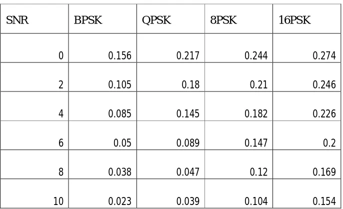
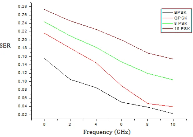
Table. 1 shows the symbol error rate for different modulation schemes at different signal to noise ratios and Fig. 12 shows the comparison of different modulation schemes.
Table. 1 Comparison of different modulation schemes
SNR
BPSK
QPSK
8PSK
16PSK
0 0.156 0.217 0.244 0.274
2 0.105 0.18 0.21 0.246
4 0.085 0.145 0.182 0.226
6 0.05 0.089 0.147 0.2
8 0.038 0.047 0.12 0.169
DOI: 10.15662/ijareeie.2014.0307037
Fig. 12 SER comparison for M-PSK schemes
V.CONCLUSION
A new methodology has been defined by designing practical 2X2 MIMO system. They are operating on UWB using practical antennas designed on CST Microwave studio, the obtained channel matrix from CST has been used for further coding MIMO, symbol Error Rate of all schemes decreases with increase in SNR. The selection of the Modulation scheme depends on the available bandwidth and the maximum data rate required. The symbol error rate is least for BPSK modulation. We observe that there is no significant change in SER performance as we switch from 8 PSK to 16 PSK so rather than increasing the complexity of the system, it is suggested to use 8 PSK in MIMO channel. MIMO systems offer an increased capacity but this requires a complex design and problems associated with mutual coupling need to be taken care of otherwise they create huge interference, also the cost for designing the system is high. The systems have been designed for 9-10 GHz frequency that is used for RADAR applications along with notching of WLAN band at the receiver side, to eliminate interference if any.
REFERENCES
[1] G.J.Foschini, “Layered space-time architecture for wireless communication in a fading environment when using multi element antennas" ,BLTJ, Autumn, 1996.
[2] Ruan Cheng-li., “UWB antenna theory and technology[M]”, Harbin industrial university press,2005.
[3] T. Svantesson, “On the Capacity and Correlation of Multi-Antenna Systems Employing Multiple Polarizations”, Proceedings of IEEE Antennas and Propagation Symposium, Vol. 3, pp. 202-205, June 2002.
[4] Emami-Forooshani and S. Noghanian, “Semi-deterministic channel model for MIMO systems Part-II: results”, IET microwaves, antennas & propagation, Vol 4, pp 26-34, 2010.
[5] Matilde Sanchez-Fernandez, Eva Rajo-Iglesias, Oscar Quevedo-Teruel and M. Luz Pablo-Gonzalez, “Spectral Efficiency in MIMO Systems Using Space and Pattern Diversities Under Compactness Constraints”, IEEE T1, 637-1645, May 2008.
[6] Mukherjee and Hyuck M. Kwon, “Compact Multi-user Wideband MIMO System Using Multiple-Mode Microstrip Antennas”, Proceedings of Vehicular Technology Conference Spring 2007, pp584-588, Apr 2007.
[7] Waldschmidt, C. Kuhnert, S. Schulteis, and W. Wiesbeck, “Compact MIMO-Arrays Based on Polarization-Diversity”, Proceedings of IEEE Antennas and Propagation. Symp., Vol 2 , pp. 499-502, June 2003.
DOI: 10.15662/ijareeie.2014.0307037 [9] Preethi Kumar and M. Jayakumar, “Comparison of Bit Error Rate for Propagation Mechanisms of Millimeter Waves in a Practical
Communication Systems Employing PSK and FSK”, PIERS Proceedings, Cambridge, USA, July 5-8, 2010.
[10] Avinash RameshchandraTrivedi, Prof. S.B.Parmar and Prof. S.B.Bhatt, “Comparison of different MIMO system using Space Time Coding in Rayleigh channel”, International Journal of Emerging Technology and Advanced Engineering, Volume 2, Issue 4, April 2012.
[11] Shubhangi Chaudhary and A.J. Patil, “Performance analysis of mimo-space time block coding with different modulation techniques”, ICTACT Journal on communication technology, March 2012, Volume: 03, Issue: 01.
BIOGRAPHY
Harshal Nigam (B.E 2011) received the B.E degree in Electronics and Communication Engineering from College of Technology and Engineering, Maharana Pratap University of Agriculture and Technology, Udaipur, Rajasthan, India in 2011. Currently, he is pursuing his Masters degree in Digital Communication from University College of Engineering, Rajasthan Technical University, Kota, Rajasthan India. He is the author of 2 IEEE International Conference papers, 1 National Conference paper and 2 International Journals till date. His research interest focuses on RF Communication, UWB antenna system design and also in the field of Wireless communications. He became a student member of IEEE in 2013.