A New Model Solid State Transformer (NMSST)
Vijayakrishna SatyamsettiDepartment of Power Electronics and Power Systems, School of Electrical Engineering, Jawaharlal Nehru Technological University Kakinada, Kakinada , India
E-mail: [email protected]
ABSTRACT:
A New Model Solid State Transformer (NMSST) is used as a controllable bidirectional transmission device that can transfer power between asynchoronous networks and functionally similar to back-to-back-HVDC . This paper describes the basic concept of a New Model Solid State Transformer (NMSST). NMSST is a new technology used for many applications like Traction , Distribution Systems, Power
Quality Improvement, Power factor
correction etc. A digital simulation model of NMSST and its control system are
developed using MATLAB. In this
application field substantial weight and volume reduction can be achieved while providing additional functionality at the same time, also in this paper a survey of recent R&D efforts in this field are presented.
KEYWORDS: Solid State Transformer
(NMSST), single phase model, three phase model , Intelligent universal transformer (IUT).
INTRODUCTION:
Revolutionary advances in semiconductor fabrication technology have made it possible significantly improve the voltage and current handling capability and the switching speed of the semiconductor devices used in power systems and its
industrial applications. Solid State Transformers (NMSST) are proposed to reduce the size of the transformer through high operating frequency, and to replace the Conventional transformers and perform voltage regulation and power exchange between generation and consumption by electrical conversion. An example of NMSST is shown in Fig 1.1
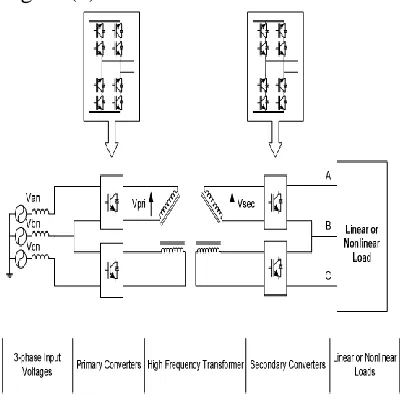
Recent progress in high power switching devices an electronic transformer is introduced as shown in Fig1.2. Multi-stage power conversion can be reduced by applying an AC/AC converter on each primary or secondary side of the transformer .desired frequency of voltage can be achieved through AC/AC converter.
2. DEVELOPMENT OF INTELLIGENT UNIVERSAL TRANSFORMER
Electrical Power Research Institute (EPRI) has been researching on Intelligent Universal Transformer(IUT) . It is proposed to replace conventional transformer with state-of-the-art power electronic system. An intelligent and controllable system can provide multiple transformer functions ,such as voltage transformation, voltage regulation ,non-standard customer voltages (DC Or 400 Hz AC), voltage sag correction , power factor control and distribution system status monitoring to facilitate automation .the iut will be a foundation of advanced distribution automation (ADA) that will transform distribution systems into multi functional power exchange systems.
The IUT assembly layout is shown as in block diagram 2.1.this layout is designed on the basics of Solid State Transformer (NMSST) as discussed earlier
2.2 DEVELOPMENT OF SINGLE PHASE SOLID STATE
TRANSFORMER
The development of NMSST is shown in Fig 2.2.Single phase ac/ac converters are applied to preimary and secondary windings of a transformers.
Table 2.1(a) requires the least number of bidirectional switches ,but large size of transformer then the development as shown in Fig 2.1(b).
The system consists of a high frequency transformer with open delta connection .single phase AC/AC converters are selected to generate high frequency voltages on transformer primary windings . on the transformer secondary side ,single phase AC/AC converter restore the voltages with input frequency .with this development the NMSST system can produce sinusoidal output voltages with no additional filters are required.
Number of semiconductor switches used in
each development is shown table 2.1
Results and discussion
CONTROL CIRCUIT :
link switches and the cycloconverter. The input data address consists of four lines. The first line is polarity of output voltage signi. The second line is switch-enabled of cycloconverter (EnableCi ). The third line is switch-enabled of dc link (EnableSi ). The fourth line provides the duty cycle data of the ith port. The enabled lines are provided by the startup and protection circuits
In this section simulation results of the proposed approach are discussed.
CONCLUSION :
In this dissertation, Design of Solid State Transformer system have been presented. The concept of electronic
transformer operating at higher frequency has been shown to effectively achieve size, weight, and volume reduction of transformer.
The single phase and three- phase electronic transformer systems have been explained and analyzed. The various application of Solid State Transformer also mentioned with effective use of Solid State Transformer Leads to replacement of utility conventional transformers .
REFERENCES :
[1] Basu, K.; Gupta, R.K.; Nath, S.; Castelino, G.F.; "Research in matrix-converter based threephase power-electronictransformers,"Power Electronics Conference (IPEC), 2010 International , vol., no., pp.27992803, 21-24 June (2010). [2] Frank R.Goodman,Jr., The EPRI Intelligent Universal Transformer (IUT), Workshop on International Standardization for Distributed Energy Resources, Vol.8, NO.10, (2009), pp. 144 28.
[3] G. Ortiz , M. Leibl , J. W. Kolar and O. Apeldoorn "Medium frequency transformer for solid- state-transformer applications Design and experimental verification “
,Proc.IEEE PEDS, pp.1285 – 1290 (2013)
[4] H. Iman-Eini and S. Farhangi, “Analysis and design of power electronic transformer for medium voltage levels,”in Proc. IEEE Power Electron. Spec. Conf., Jun. (2006,) pp.1–5.
[5] H. F. Fan and H. Li "High frequency transformerisolated bidirectional DC-DC converter modules with highefficiency over wide load range for 20 kVA solid state transformer", IEEE. PowerElectron., vol. 26, pp.3599 -3608 ( 2011 )
EngineeringVol. 1, No. 2, Summer & Fall (2013), Pages: 147-155
[7]J.H.Harlow ElectricPowerTransformerE
ngineering, ( 2007 ) :CRC press
[8] S. Bala , D. Das , E. Aeloiza , A. Maitra and S. Bajagopalan "Hybrid transformer: Conceptdevelopmentandfileddemonstration"
, Proc. IEEE ECCE, pp.4061 -4068 2012.
[9] W.M.ColonelandT.Mclyman Transform
er and Inductor Design Handbook, (2004)