International Journal of Research (IJR)
e-ISSN: 2348-6848, p- ISSN: 2348-795X Volume 2, Issue 07, July 2015Available at http://internationaljournalofresearch.org
Available online:http://internationaljournalofresearch.org/ P a g e | 717
Design of Three-Phase to Five-Phase Transformation Using
a STC
Dande sai sowjanya
Assistant professor, SVIT, HYDERABAD, INDIA.
Abstract—
The first five-phase induction motor drive system was proposed in the late 1970s for adjustable speed drive applications. Since then, a considerable research effort has been in place to develop commercially feasible multiphase drive systems. Since the three-phase supply is available from the grid, there is a need to develop a static phase transformation system to obtain a multiphase supply from the available three-phase supply. Thus, this paper proposes a novel transformer connection scheme to convert the three phase grid supply to a five-phase fixed voltage and fixed frequency supply. The proposed transformer connection outputs five phases and, thus, can be used in applications requiring a five-phase supply. Currently, the five-phase motor drive is a commercially viable solution. The five-phase transmission system can be investigated further as an efficient solution for bulk power transfer. The connection scheme is elaborated by using the simulation and experimental approach to prove the viability of the implementation. The geometry of the fabricated transformer is elaborated in this paper.
Index Terms—Five phase; multiphase; three phase; transformer; turn ratio
I. INTRODUCTION
Systems are the focus of research recently due to their inherent advantages compared to their three-phase counterparts. The applicability of multiphase systems is explored in electric power generation [2]–[8], transmission [9]–[15], and utilization [16]–[33]. The research on six-phase transmission system was initiated due to the rising cost of right of way for transmission corridors, environmental issues, and various stringent licensing laws. Six phase transmission lines can provide the same power capacity with a lower phase-to-phase voltage and smaller, more compact towers compared to a standard double-circuit three-phase line. The geometry of the six-phase compact towers may also aid in the reduction of magnetic fields as well [12]. The research on multiphase generators has started recently and only a few references are available [2]–[8]. The present work on multiphase generation has investigated asymmetrical six-phase (two sets of stator windings with 30 six-phase displacement) induction generator configuration as the solution for use in renewable energy generation. As far as multiphase motor drives are concerned, the first proposal was given by Ward and Harrier way back in 1969 [1] and since then,
International Journal of Research (IJR)
e-ISSN: 2348-6848, p- ISSN: 2348-795X Volume 2, Issue 07, July 2015Available at http://internationaljournalofresearch.org
Available online:http://internationaljournalofresearch.org/ P a g e | 718
of choice for a 6-, 12-, or 24-phase system is that these numbers are multiples of three and designing this type of system is simple and straightforward. However, increasing the number of phases certainly enhances the complexity of the system. None of these designs are available for an odd number of phases, such as 5, 7, 11, etc., as far as the authors know.
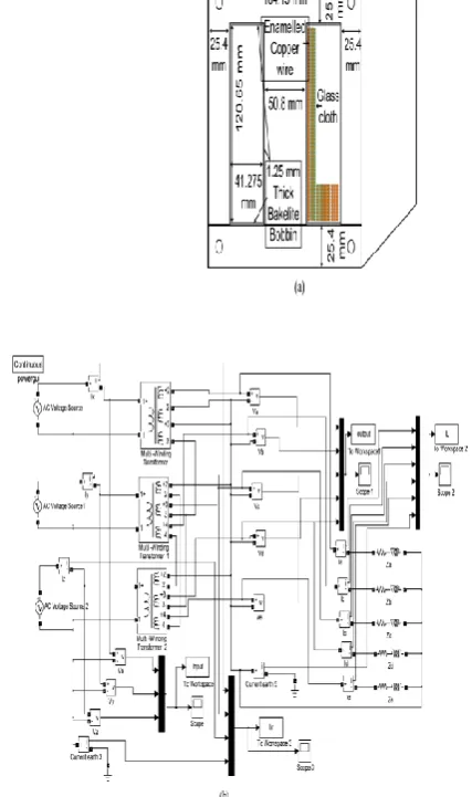
The usual practice is to test the designed motor for a number of operating conditions with a pure sinusoidal supply to ascertain the desired performance of the motor [38]. Normally, a no-load test, blocked rotor, and no-load tests are performed on a motor to determine its parameters. Although the supply used for a multiphase motor drive obtained from a multiphase inverter could have more current ripple, there are control methods available to lower the current distortion even below 1%, based on application and requirement. Hence, the machine parameters obtained by using the pulsewidth-modulated (PWM) supply may not provide the precise true value. Thus, a pure sinusoidal supply system available from the utility grid is required to feed the motor. This paper proposes a special transformer connection scheme to obtain a balanced five-phase supply with the input as balanced three phase. The block diagram of the proposed system is shown in Fig. 1. The fixed voltage and fixed frequency available grid supply can be transformed to the fixed voltage and fixed frequency five-phase output supply. The output, however, may be made variable by inserting the autotransformer at the input side.
The input and output supply can be arranged in the following manner:
1) input star, output star; 2) input star, output polygon; 3) input delta, output star; 4) input delta, output polygon.
International Journal of Research (IJR)
e-ISSN: 2348-6848, p- ISSN: 2348-795X Volume 2, Issue 07, July 2015Available at http://internationaljournalofresearch.org
Available online:http://internationaljournalofresearch.org/ P a g e | 719
II. WINDING ARRANGEMENT FOR FIVE-PHASE STAR OUTPUT
Three separate cores are designed with each carrying one primary and three secondary coils, except in one core where only two secondary coils are used. Six terminals of primaries are connected in an appropriate manner resulting in star and/or delta connections and the 16 terminals of secondary’s are connected in a different fashion resulting in star or polygon output. The connection scheme of secondary windings to obtain a star output is illustrated in Fig. 2 and the corresponding pharos diagram is illustrated in Fig. 3. The construction of output phases with requisite phase angles of 72 between each phase is obtained using in an usual fashion. The output/secondary side connection is discussed in the following subsections.
appropriate turn ratios, and the governing pharos equations are illustrated in (1)–(10). The turn ratios are different in each phase. The choice of turn ratio is the key in creating the requisite phase displacement in the output phases. The input phases are designated with letters ―X‖ ―Y‖, and ―Z‖ and the output are designated with letters ―A‖, ―B‖, ―C‖, ―D‖, and ―E‖. As illustrated in Fig. 3, the output phase ―A‖ is along the input phase ―X‖. The output phase ―B‖ results from the pharos sum of winding voltage ―c6c5 ‖ and ―b1b2 ‖, the output phase ―C‖ is obtained by the pharos sum of winding voltages ―a4a3 ‖ and ―bb3b4 ‖. The output phase ―D‖ is obtained by the pharos addition of winding voltages ―a4a3 ‖
International Journal of Research (IJR)
e-ISSN: 2348-6848, p- ISSN: 2348-795X Volume 2, Issue 07, July 2015Available at http://internationaljournalofresearch.org
Available online:http://internationaljournalofresearch.org/ P a g e | 720
III. SIMULATION RESULTS
International Journal of Research (IJR)
e-ISSN: 2348-6848, p- ISSN: 2348-795X Volume 2, Issue 07, July 2015Available at http://internationaljournalofresearch.org
Available online:http://internationaljournalofresearch.org/ P a g e | 721
International Journal of Research (IJR)
e-ISSN: 2348-6848, p- ISSN: 2348-795X Volume 2, Issue 07, July 2015Available at http://internationaljournalofresearch.org
Available online:http://internationaljournalofresearch.org/ P a g e | 722
IV. EXPERIMENTAL RESULTS
This section elaborates the experimental setup and the results obtained by using the designed three- to five-phase transformation system. The designed transformation system has a 1:1 input:output ratio, hence, the output voltage is equal to the input voltage. Nevertheless, this ratio can be altered to suit the stepup or stepdown requirements. This can be achieved by simply multiplying the gain factor in the turn ratios. In the present scheme for experimental purposes, three singlephase autotransformers are used to supply input phases of the transformer connections. The output voltages can be adjusted
International Journal of Research (IJR)
e-ISSN: 2348-6848, p- ISSN: 2348-795X Volume 2, Issue 07, July 2015Available at http://internationaljournalofresearch.org
Available online:http://internationaljournalofresearch.org/ P a g e | 723
Further tests are conducted under load conditions on the designed transformation system by feeding a five-phase induction motor. The experimental setup is depicted in Fig. 7. Direct online starting is done for a five-phase induction motor which is loaded by using an eddy-current load system. DC current of 0.5 A is applied as the eddy-current load on the five-phase induction machine. The resulting input (three-phase) waveforms and the output (five-phase) waveforms (voltages and currents) are shown in Figs. 8 and 9, respectively, under steady state. The applied voltage to the input side is 446 V (peak to peak) , the power factor is 0.3971, and the steady-state current is seen as 7.6 A (peak-to-peak). The corresponding waveforms of the same phase ―A‖ are equal to the input side voltage of 446 (peak-to peak), since the transformer winding has a 1:1 ratio. The power factor is now reduced in the secondary side and is equal to 0.324 and the steady-state current reduces to 3.3 A (peak-to-peak). The reduction in steady-state current is due to the increase in the number of output phases. Thus, once again, it is proved that the deigned transformation systems work satisfactorily. The transient performance of the three- to five-phase transformer is evaluated by recording the transient current when sup-plying the five-phase
induction motor load. The maximum peak transient current is recorded as 7.04 A which is reduced to 4.32 A in the steady-state condition. The settling time is recorded to be equal to 438.4 ms as depicted in Fig. 10.
V. CONCLUSION
This paper proposes a new transformer connection scheme to transform the three-phase grid power to a five-phase output supply. The connection scheme and the phasor diagram along with the turn ratios are illustrated. The successful implementation of the proposed connection scheme is elaborated by using simulation and experimentation. A five-phase induction motor under a loaded condition is used to prove the viability of the transformation system. It is expected that the proposed connection scheme can be used in drives applications and may also be further explored to be utilized in multiphase power transmission
REFERENCES
[1] E. E. Ward and H. Harer, ―Preliminary investigation of an inverter-fed 5-phase induction motor,‖ Proc. Inst. Elect. Eng., vol. 116, no. 6, 1969.
[2] D. Basic, J. G. Zhu, and G. Boardman, ―Transient performance study of brushless doubly fed twin stator generator,‖ IEEE Trans. Energy
Convers., vol. 18, no. 3, pp. 400–408, Jul. 2003.
[3] G. K. Singh, ―Self excited induction generator research- a survey,‖ Elect. Power Syst. Res., vol. 69, pp. 107–114, 2004.
[4] O. Ojo and I. E. Davidson, ―PWM-VSI inverter-assisted stand-alone dual stator winding induction generator,‖ IEEE Trans Ind. Appl., vol. 36, no. 6, pp. 1604–1611, Nov./Dec. 2000.
[5] G. K. Singh, K. B. Yadav, and R. P. Saini, ―Modelling and analysis of multiphase (six-phase) self-excited induction generator,‖ in Proc. Eight Int. Conf. on Electric Machines and
International Journal of Research (IJR)
e-ISSN: 2348-6848, p- ISSN: 2348-795X Volume 2, Issue 07, July 2015Available at http://internationaljournalofresearch.org
Available online:http://internationaljournalofresearch.org/ P a g e | 724
[6] G. K. Singh, K. B. Yadav, and R. P. Sani, ―Analysis of saturated multiphase (six-phase) self excited induction generator,‖ Int. J. Emerging
Elect. Power Syst., Article 5, vol. 7, no. 2, Sep.
2006.
[7] G. K. Singh, K. B. Yadav, and R. P. Sani, ―Capacitive self-excitation in six-phase induction generator for small hydro power-an experimental investigation,‖ presented at the IEEE Conf. Power Electronics, Drives and Energy Systems for Industrial Growth—2006 (PEDES-2006) PaperA- 20. (CD-ROM), New Delhi, India, Dec. 12–15, 2006.
[8] G. K. Singh, ―Modelling and experimental analysis of a self excited six-phase induction generator for stand alone renewable energy generation,‖ Renew. Energy, vol. 33, no. 7, pp. 1605–162, Jul. 2008.
[9] J. R. Stewart and D. D.Wilson, ―High phase order transmission- a feasibility analysis Part-I-Steady state considerations,‖ IEEE Trans. Power
App. Syst., vol. PAS-97, no. 6, pp. 2300–2307,
Nov. 1978.
[10] J. R. Stewart and D. D. Wilson, ―High phase order transmission- a feasibility analysis Part-II-Over voltages and insulation requirements,‖
IEEE Trans. Power App. Syst., vol. PAS-97, no.
6, pp. 2308–2317, Nov. 1978.
[11] J. R. Stewart, E. Kallaur, and J. S. Grant, ―Economics of EHV high phase order transmission,‖ IEEE Trans. Power App. Syst., vol. PAS- 103, no. 11, pp. 3386–3392, Nov. 1984.
[12] S. N. Tewari, G. K. Singh, and A. B. Saroor, ―Multiphase power transmission research-a survey,‖ Elect. Power Syst. Res., vol. 24, pp. 207–215, 1992.
[13] C. M. Portela and M. C. Tavares, ―Six-phase transmission line-propagation characteristics and new three-phase representation,‖ IEEE Trans.
Power Del., vol. 18, no. 3, pp. 1470–1483, Jul.
1993.
[14] T. L. Landers, R. J. Richeda, E. Krizanskas, J. R. Stewart, and R. A. Brown, ―High phase order economics: Constructing a newtransmission line,‖ IEEE Trans. Power Del., vol. 13, no. 4, pp. 1521–1526, Oct. 1998.
[15] J. M. Arroyo and A. J. Conejo, ―Optimal response of power generators to energy, AGC, and reserve pool based markets,‖ IEEE Power
Eng. Rev., vol. 22, no. 4, pp. 76–77, Apr. 2002.