Simple and Cost Effective Foot Pressure
Detection System for Diabetic Patients
Ramana R G1, Ajit Rao2, Rambabu K2, Prakash K3
Assistant Professor, Dept. of ECE, Nalanda Institute of Technology, Guntur Dt., India1
Assistant Professor, Dept. of ECE, Brilliant Institute of Engineering and Technology, Hyderabad, India2
Professor, Dept. of ECE, Brilliant Institute of Engineering and Technology, Hyderabad, India3
ABSTRACT: As the pebble rate numbness in the sensory points of the feet caused by diabetes in common person will be detected using piezoelectric sensors. Very low cost sensors are embed in the footwear platform to detect pressure. Embedded system compatible to sensing, wearable electronics interfaced to mobile are regular prominent technologies. Using appropriate microcontroller, the output signals of interfaced piezoelectric sensors are received to analog input and are serially transmitted to the android application which uses bluetooth service. Present developing detection processes includes ZigBee and GSM module, which are not cost effective for common use. We prefer piezoelectric sensor which is low cost, easy to embed in footwear and has high sensitive properties with energy generation capacity. Hence this implemented system can be self-powered, feasible, easy to maintain and user friendly.
KEYWORDS: Sensors, Signal conditioning system, Electret, Piezoelectric (pzt), Ulcers, Diabetic neuropathy.
I.INTRODUCTION
Sensor is a device that vibrate, measures a physical quantity and converts it into a signal which can be interfaced to a system. Loss of any kind of functions to leg leads deleterious to the patient and mostly to the diabetes patients. Diabetes mellitus (DM) is reported to be an important cause of diabetic ulcer disease [1, 2]. Diabetes related foot complications can be detected early through provision of education and appropriate foot care [3]. SUDOSCAN: a non-invasive and quick method, PRESSURE detection: normalized peak pressure and pressure contact ratio are basic elements to prevent complications and amputations. It is also found that the foot pressure parameters are functions of the material properties of foot sole soft tissue and also different levels of sensation loss. The normal path way of monitoring is the painful to the patient [4, 5, 6].
Energy harvesting and other applications of piezoelectrics has widely studied and used [7]. Effective circuits, different concepts [8, 9], integration of sensor with electronics have been investigated for better applications [10, 11, 12].Few companies developed only platform to avoid the numbness and foot ulcers. But, no feedback was be taken in the existed models. Ignored and untreated, minor sores on the skin of the foot can turn into severe problems with potentially devastating consequences, namely, numbness which turn into foot ulcers in later stages so protective way and independent risk study was proposed as a simple monitoring system to predict the foot ulcers in patients. Related to this concept recent developments on security was done by researchers. Pressure points data can be easily noticed and record the data. Simple GUI based android electronic tool can warn the patient periodically.
II. PIEZOELECTRIC SENSORS AND ESTIMATIONS
result in a sheet charge which would be collected on the surface of the solid. If a sufficient force is applied normal to the piezoelectric crystal, a deformation will take place. This deformation disrupts the orientation of the aligned electrical dipoles and creates a situation in which the surface charge is not completely cancelled. This results in a temporary excess of surface charge, which subsequently manifested as a voltage which is developed across the crystal to store in an external capacitor.
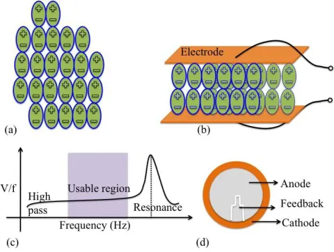
Fig 1. (a) Internal structure of an electret material, (b) Common method of piezo electric charge collection with electrodes on top and bottom layer, (c) Piezo-electric frequency response, (d) Readily available piezo-electric sensor
with electrodes of anode and cathode.
The principle to make a sensor to detect force, we must be able to utilizing the physical material by measure of surface charge on the crystal [13]. Figure 1(b) shows a regular capacitive method of using a piezoelectric crystal to make a force sensor [14]. Two metal plates are used to sandwich the crystal making a capacitor i.e metal-piezomaterial-meatal structure. In its operating region, a greater force will result in more surface charge. This charge results in a relation to voltage and capacitor, which is Vc = Qf/Cp, where Qf is the charge resulting from a force f, and
Cpis the capacitance of the piezo device. Frequency response of piezoelectric sensor is shown in the figure 1(c), which shows peak voltage at resonant frequency.
Piezoelectric crystals act as transducers which turn force, or mechanical stress into an electrical charge which in turn can be converted into a measurable voltage to read by the analog inputs. Microphone (mechanical to electrical) and speakers (voltage to mechanical) are two major applications of piezoelectric transducer. This principle of PZT sensor can be utilized to detect the numbness in the foot of diabetic patients. Piezoelectric sensor has three terminals namely anode, cathode and feedback as shown in the Figure 1(d). Feedback terminal gives the feedback signals which drive the oscillator. This terminal makes the sensor a self-drive device which makes the sensor to act as high sensitive at its resonant frequency.
III. SYSTEM DESIGN
A). Design of the sensors platform:
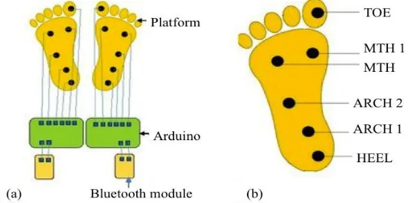
Foot placing platform consists of 3 layers (soft silicon – sensor mounting rubber- hard silicon) which are shown in Figure 2(a) and total assembly has 5 mm thickness, in which top and bottom layers are silicon sheets. Mid layer is a rubber sheet, which is attached to the bottom layer. In the mid layer grooves are made at preferred pressure point locations using specific cutting tool 13 mm diameter. Figure 2(b) shows grooves, piezoelectric sensors are placed and also proper path is cut to take wiring sensor and analog inputs of microcontroller.
Total 6 grooves are made at each side of the platform i.e., for left foot and right foot. The piezoelectric sensors are of 12 mm diameter, total 12 sensors are placed at 12 grooves. In the top layer, 13 mm, extrudes are made and each extrude will fit into the grooves of the mid layer.
Fig.2 (a) Sensor mounting view, (b) Developed platform for sensor placement (inside view and top view)
B) Overall System Representation:
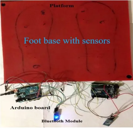
Wires from each sensor of each side of platform are connected to the respective Arduino board analog I/O pins, which is shown in the figure 3(a). Bluetooth module is connected to the RX and TX pin of the Arduino board respectively and remaining pins are connected as indicated on the datasheet. Placement of sensor to measure the foot pressure distribution suggested are 6. These six areas are heel, metatarsal head 1 (MTH1), metatarsal head (MTH) (high pressure areas), toe and arch 1 (medium pressure areas), arch 2 (low pressure area). We have identified four locations to give optimized pressure distribution and complexity of sensing system. Figure 3(b) shows the layout of the sensors placement in order to measure the pressure distribution of the foot.
C). Working principle:
The person who suffering from diabetic neuropathy is being asked to stand on the platform, pressure gets applied on the sensor due to the projections on the top layer. Signals are generated in the form of pulse. These signals are received by the analog I/O pins of microcontroller (figure 4) and processes the signals. The output of the Arduino board are fed to Bluetooth module. Data was serially transmitted to the smartphone and displayed in the designed GUI application.
Fig. 4. Working system, data transmitted to android based mobile for monitoring the high pressure points.
IV. SIMULATIONS AND MODELING
With applied load on the pzt sensor, we observed noticeable change in the signal. The model of sensor structure was estimated/simulated with ANSYS tool. Simulation results shown in Figure 5 with distribution load and point contact load. In simulation tool the sensor material was taken as copper with young’s modulus / elastic modulus was 110 GPA. We tested at different load conditions and shown in Figure 5 (a), (b), (c) i.e. 40kg, 60kg, 80kg respectively. Also a point contact test with load of 50kg (figure 5(d)) was done and it shows significant change w.r.t uniform load distribution. Point load is taken into consideration as the application of pressure on the solder over the sensor. Due to the solder contact, more pressure can act over the sensor.
After applying uniformly distributed load and point load, the maximum stress was observed at the edges of the value 15097.7, 22646.5, 30195 upon applying 40 kg, 60 kg, and 80 kg respectively. For point load the maximum stress value of 6982.68 upon applying 50kg. Different forces acting on sensor are being computed with the help of stress and strain relations. The stress acting on the sensor is being calculated with the below relation.
Stress = (load/cross sectional area) = and the axial deformation is calculated using .
V. RESULT AND DISCUSSION
A person step on the platform, the pressure applied to all the sensors was not the same, thus the output from each sensor will be different. The observed output from PZT sensor is shown in below Figure 6.
Fig. 6. PZT responses with respect time as we apply the load.
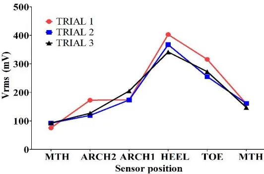
There was output change in each sensor according to the pressure level and noticeable change in the heel part sense area of the foot. This was the basic test done to optimise the sensor result for further process. Repeated tests shows the comparatively similar responses. Green marked line shows the heel part data at high peak response. MTH, ARCH1, ARCH2 points have a reasonable response and it is less than the heel point response. Several experiments with many sensors conducted and recoded in the digital CRO.
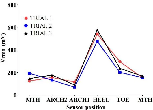
All analog input pins read values when we step onto the developed platform. Graph was computed for 6 sensors data taking in X-axis and response of sensor (voltage) in the Y-axis. Three trails has been conducted (figure 7) to notice the repeatability of the system. Figure 7 & 8 shows left foot and the right foot responses in multiple tests with the same platform. In the data the heel pressure point has recorded consistent values for several trials. This data shows the stability in sensors and system performance.
Fig. 8. Right foot sensor data in three trials
From both Figures 7 & 8, results we observed that HEEL exhibits more pressure. When we step on MTH sensory point, which read as a least pressure point. Figure 6 shows the Digital oscilloscope reading of the MTH, ARCH 2, ARCH 1 and HEEL sensory points. The green line data in figure 6 indicates the HEEL sensory point and has high output response compared to the other sensory points. These repeatable data can be used to optimize the platform and system can perform better.
VI.CONCLUSION
Foot pressure sensing platform system is developed using piezo-electric sensors to early detection of foot ulcer caused by diabetic conditions. This system used to measure pressures on foot at HEEL, MT, MT1, TOE, ARCH1 and ARCH2 locations. The result shows the comparisons of the pressure distribution on foot with different trials to detect the numbness and avoid the foot ulcers. This system can aid in deciding suitable foot wear for diabetic patients and walking style for a given time based on the data read sensor and shown in the hand held device. It is envisioned that the said technique, developed and tested is effective biomechanical system to diagnose various disorders related to foot. Remotely, data can be accessible using inbuilt gsm module is a trend to resolve many of the medical problems.
REFERENCES
[1] S. L. atil, Madhuri A. Thatte, u. M. Chaskar,“Development of Planter Foot Pressure Distribution System Using Flexi Force Sensors,” Sensors& Transducers Journal, Vol. 108, Issue 9, pp. 73-79, 2009.
[2] Kumarasinghe A. Sriyani, SudharshaniWasalathanthri, PriyadharshikaHettiarachchi, ShaminiPrathapan,“Predictors of Diabetic Foot and Leg Ulcers in a Developing Country with a Rapid Increase in the Prevalence of Diabetes Mellitus,”Vol. 8, Issue 11, November 2013.
[3] S. Krishna Priya, A.N.Nithyaa, R.PremKumar,“Screening Of Foot Ulceration in Diabetic Neuropathy Patients Using Flexi Force Sensor Platform,” International Journal of Scientific & Engineering Research, Vol. 5, Issue 4,87, ISSN 2229-5518, pp. 87-93, April-2014.
[4] K. Khalfallah, H. Ayoub, J. Hentrycalvet, X. Neveu, P. Brunswick, S Griveau, V. Lair and F. Bedioui,“Noninvasive Galvanic Skin Sensor for Early Diagnosis of Sudomotor Dysfunction,” Application To Diabetics, IEEE Sensors Journal, Vol.12, Issue.3, march 2012.
[6] R. G. Frykberg, T.Zgonis, G. D. Armstrong, V. R. Driver,M. J.Giurini, R. K.Steven, A. S. Landsman, L. A.Lavery, J. C. Moore, M.John K.Schuberth,Dane,Wukich, Charles Andersen, and J.V. Vanore,“Diabetic foot Disorder-A clinical Practice,The journal of Foot &Ankle surgery,” Vol. 45, Issue 5, October 2006.
[7] H.A.Sodano, D.J.Inman, and G. Park, “A review of power harvestingfrom vibration using piezoelectric materials,” Shock Vibr. Dig., 36, pp. 197–205, 2004.
[8] F. Cottone, H. Vocca, and L.Gammaitoni, “Nonlinear energy harvesting,”Phys. Rev. Lett., 102, pp. 080601, 2009.
[9] J. b. Yuan, X. b. Shan, T. Xie, and W. Chen, “Energy harvestingwith a slotted-cymbal transducer,” J. Zhejiang Univ. Sci. A, 10,(8), pp. 1187–1190, 2009.
[10]M.Umeda, K. Nakamura, and S. Ueha, “Energy storage characteristicsof a piezogeneratorusing impact induced vibration,”Jpn. J. Appl. Phys., 36, pp. 3146–3151, 1997.
[11]Y.K.Ramadass, and A. P. Chandrakasan, “An efficient piezoelectricenergy harvesting interface circuit bias flip rectifier and shared inductor,”IEEE J. Solid-State Circuits, 45, pp. 189–204, 2010
[12]8 Glynne-Jones, P., Beeby, S.P., and White, N.M.: ‘Towards a piezoelectricvibration-powered microgenerator’, IEE Proc., Sci. Meas. Technol., 148, pp. 68, 2001.
[13]Dahl, R. Philip, J. Joseph, Gerardi, and A. G. Hickman, “Piezoelectric sensor,” U.S. Patent No. 5,191,791. 9 Mar. 1993.