Optimization of Quasi-Constant Mutual Inductance of Asymmetrical
Coils with Lateral Misalignment in Wireless Power Transfer System
Zhongqi Li, Jing Li, Jiliang Yi, Wuxian Liao*, and Min Zhang
Abstract—In the wireless power transfer system (WPT) via magnetically coupled resonance, the lateral misalignment between the transmission coil and receiving coil may affect the mutual inductance, then the transfer efficiency may be decreased, and the output power may be fluctuated, which lead to an unstable system. In this paper, a calculation method of the mutual inductance of an asymmetrical two-coil structure is presented. Based on the mutual inductance calculation method, an optimization method of quasi-constant mutual inductance is proposed. The key parameters of each coil can be obtained by using the proposed method. The mutual inductance can be kept constant when the misalignment is changed. And the output voltage and efficiency are also nearly constant with different misalignments. Finally, the setup of the asymmetric two-coil WPT system via magnetically coupled resonance is designed. Calculation, simulation, and experimental results validating the proposed method are given.
1. INTRODUCTION
WPT technology is currently a research hotspot [1, 2]. The technology has broad application prospect in the field of electric vehicles [3], consumer electronics, aerospace, biological and medical science [1]. However, there exists the problem of the changes of various parameters in a WPT system. Especially the mutual inductance and load have a great influence on the system. And there is mutual coupling between the mutual inductance and the load. In order to obtain the best performance, the load should follow the change of the mutual inductance (Each mutual inductance will correspond to an optimal load to obtain the maximum efficiency or maximum power.) [4]. Once the characteristic of quasi-constant mutual inductance was obtained, the mutual inductance and load were decoupled. In practical applications, the lateral misalignment between the transmission coil and receiving coil was changed, which caused the change of the mutual inductance. The change of the mutual inductance caused the fluctuation of the output voltage and the reduction of the efficiency. In order to cope with the problem, scholars have carried out research in the following three aspects: (1) Control method; (2) Resonance compensation network; (3) Design of coils.
In the aspect of control method, in order to solve the problem, PWM control method and phase shift control method are often used. When the mutual inductance was changed, the output voltage could be adjusted by changing the duty ratio of the PWM, and the output voltage was also adjusted by changing the phase angle. The switching of these control methods generally works in a hard switching state. Therefore, the system has large losses [4]. Currently, some scholars have introduced an LLC resonant converter into a WPT system. The LLC resonant converter can improve the efficiency of the system. However, the soft switch is limited by the variation of parameters of the system because the adjustments of the frequency will cause the change of the fundamental frequency, which affects the resonance compensation network [5].
Received 2 August 2019, Accepted 17 September 2019, Scheduled 31 October 2019
* Corresponding author: Wuxian Liao ([email protected]).
In the resonance compensation network, in order to solve the problem of the fluctuation of output voltage and the reduction of efficiency caused by the change of mutual inductance, impedance matching network is often used, including the types of SPS [6], LCL [7], LCC [8], T [9], LC, π, and DC-DC of active impedance topology [10]. Therefore, the WPT system must be increased with two or more impedance networks or conversion devices. However, the use of more complicated devices may reduce the reliability of the system and have an impact on the efficiency of the system [11].
The adverse effects of the change of mutual inductance on the WPT system can be reduced by using the above two methods. However, the mutual inductance was still changed when the misalignment was changed. In order to keep the mutual inductance constant with misalignment, Korea Advanced Institute of Science and Technology has developed power supply of long-rail type of E, U, W, I, and S [12]. These structures allow larger lateral misalignment of the receiving coil. However, there are also two disadvantages: (1) the receiving coil can cover only a part of the long rail (the receiving coil), which inevitably reduces the coupling coefficient between the receiving coil and transmission coil. Therefore, the system efficiency is not high; (2) the fluctuation of the mutual inductance is not small. A structure of multi-transmission coil was proposed [13–15] to solve the problem of the fluctuation of the mutual inductance. The magnetic field distribution was homogeneous in this structure when the receiving coil moved on the field. And the efficiency of the WPT system was almost unchanged. However, the transmission device was composed of small transmission coils. The quality factor was generally low, which reduced the efficiency of the WPT system. Therefore, [16] studied the magnetic coupling structure of six transmission coils to a receiving coil, and the quality factor of the coil was improved. When the receiving coil moved along the Y-axis direction, the fluctuation of the output power was ±7.5%. However, the performance along the X-axis direction is worse than that along the
Y-axis direction. In summary, in order to obtain constant mutual inductance between the transmission coil and receiving coil, it is necessary to analyze the characteristics of the mutual inductance of the WPT system.
A structure of asymmetric two-coil is analyzed in this paper. And the calculation method of mutual inductance is given. Then an optimization method of mutual inductance is proposed. The parameters of each coil are obtained by using the proposed optimization method and structure. The mutual inductance can be kept constant with misalignments. The effectiveness and correctness of the optimization method are verified by the simulated and experimental results.
2. MATHEMATICAL MODEL
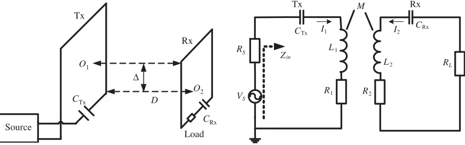
Figure 1 shows the WPT system of asymmetrical two coils. It consists of a source, a transmission coil (Tx), a receiving coil (Rx), and the load. Tx is larger than Rx in size. Variable Δ is the lateral misalignment; O1 and O2 are the centers of Tx and Rx respectively; D is the transmission distance
between Tx and Rx; CTx is the resonant capacitance of Tx; CRx is the resonant capacitance of Rx.
In order to analyze circuit conveniently, the WPT system can be represented in terms of lumped
Source
D Tx
CRx Rx
O1
O2 CTx
Load
Δ
Figure 1. WPT system of asymmetrical square coils.
Tx M Rx
CRx
CTx
RS
VS
I1 I2
L1
L2
R1 R2
Zin
RL
circuit elements (L,C, andR), as shown in Fig. 2. VariableVs is the voltage source;Rs is the internal
resistance of the source;R1 andR2 are the internal resistances of Tx and Rx, respectively. Variable RL
is the load;L1 and L2 are the self-inductances of Tx and Rx, respectively; M is the mutual inductance
between Tx and Rx;ω is the operating frequency of the system;I1 is the current of Tx;I2 is the current
of Rx.
By applying Kirchhoff’s voltage law (KVL), the asymmetrical two-coil WPT system is presented
as follows:
Z1I1+jωM I2 =Vs
jωM I1+Z2I2 = 0
(1)
Z1 =RS+R1+jωL1+ 1/(jωCTx)
Z2 =RL+R2+jωL2+ 1/(jωCRx)
(2)
The currents of Tx and Rx can be obtained by solving Eqs. (1) and (2). ⎧ ⎪ ⎪ ⎨ ⎪ ⎪ ⎩
I1 = VsZ2
Z1Z2+ (ωM)2
I2 =− jωM Vs
Z1Z2+ (ωM)2
(3)
The expression of the transmission efficiency is as follows:
η= I
2 2RL
VsI1
= (ωM)
2R L
Z1Z22+ (ωM)2Z2
(4)
When the WPT system of asymmetrical two coils operates in a resonant state, we haveZ1 =Rs+R1
and Z2 =RL+R2. Equation (4) can be simplified as follows:
η = I
2 2RL
VsI1
= (ωM)
2R L
(Rs+R1)(RL+R2)2+ (ωM)2(RL+R2)
(5)
According to Eq. (3), the expression of the output voltage in the WPT system is obtained:
VL= (R −jωM VsRL
s+R1)(RL+R2) + (ωM)2
(6)
It can be seen from Eqs. (5) and (6) that mutual inductance is a key parameter for efficiency and output voltage. In practical applications, the change of M may cause the decrease of transmission efficiency and the fluctuation of output voltage. Then the safety and reliability of the WPT system may be reduced. M is dependent on the size and relative position of each coil. In order to keep the mutual inductance constant, it is necessary to study the calculation and optimization method of the mutual inductance.
3. CALCULATION OF MUTUAL INDUCTANCE
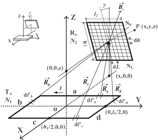
In this section, a calculation method of the mutual inductance of the rectangular coil is presented. Fig. 3 depicts two single-turn rectangular coils with any position. Variablel1is the length of Tx, andh1 is the
width of Tx. Variablel2 is the length of Rx, andh2 is the width of Rx. Variableγ is the angle between
Rx plane andY OZ plane. Tx is separated by four parts (line a, line b, line c, and line d). Ra,Rb,Rc,
andRdare distance vectors from line a, line b, line c, and line d to any arbitrary center pointP(x, y, z)
of Rx, respectively. It is assumed that rectangular coils have homogeneous current distribution and consist of filament [17, 18].
For the convenience of calculation, the receiving coil is subdivided. The number of small rectangles subdivided is NL×Nh. Parameters dL and dh are the length and width of Rx, respectively. It is
assumed that the magnetic flux density is uniformly distributed at the center point in each subdivision. Based on Biot-Savart’s law, the magnetic flux density Bij at P(x, y, z) caused by the current I is as
follows:
Bij = μ40πI
c
dl×R R3
b
R Rc
a
R Rd
i
B →
→
→ → →
Figure 3. Schematic diagram of two non-coaxial rectangular coils.
whereμ0 is the magnetic permeability in vacuum,c line of Tx, andIdl a current micro-element onc.
The mutual inductance between Tx and Rx can be obtained:
M11=
1
I
S2
Bij·dS2 (8)
whereS2 is the area of Rx, andI is the current of Tx.
It can be seen that the magnetic flux density in Y direction is only generated by line b and line d. The dot product between the normal vector of Rx plane and the field of Y direction from line b or line dis zero. According to Eq. (8), the magnetic flux density in Y direction of Rx does not affect the mutual inductance. Then only the magnetic flux density inX and Z directions needs to be considered. And the magnetic flux density inX direction is only generated by line and line c. Therefore, a specific mutual inductance calculation formula between the single-turn coils is obtained:
M11|0◦≤γ<180◦=
dLdh I
NL=l2/dL
j=1
Nh=h2/dh
i=1
−Bxijcosγ+Bzijsinγ (9)
The mutual inductance between multi-turn coils can be calculated:
M =
N1
k=1 N2
s=1
Mks (10)
where N1 is the number of turns of Tx, N2 the number of turns of Rx, k the k-th turn of Tx, and s
the s-th turn of Rx. The theory in this section provides a method of calculating mutual inductance between Tx and Rx for the next section.
4. OPTIMIZATION METHOD
START
Parameters setting: the distance between two coils, the diameter of copper
Initialization of the parameters: M_10* , M _0*,
,
* the number of turns of T
x(N1*) and Rx
(N2*), the outer side length of Tx(l1*) and Rx(l2*)
The inner side length of Txsetting
l 1_Min≤ l (i) 1 ≤ l1_Max
The inner side length of Rxsetting
The number of turns of Txsetting
The number of turns of Rxsetting
Calculating mutual inductances between Txand Rxwith different lateral
misalignment according to (9) and (10)
ε(i)<ε*
& M_10(i)<M_10
*
Saved and outputted parameters:
M_10*= M_10(i) M_0*= M_0(i)
N1*= N1(i) , N2*= N2(i)
l1*=l1(i)+4×N1(i),
l2 *
=l2(i)+4×N2(i)
N2(i)<N2_Max
N1(i)<N1_Max
l2(i)<l2_Max
l1(i)<l1_Max
END
Output all optimal parameters
N2(i)=N2(i)+1
N1(i)=N1(i)+1
N2(i)=N2_Min
l2(i)=l2(i)+1cm
l1(i)=l1(i)+1cm
l2(i)=l2_Min
N1(i)=N1_Min
N2(i)=N2_Min
Y N
Y
N
Y
N
Y
N
Y
N ε
l 2_Min≤ l (i) 2 ≤ l2_Max
N 1_Min≤ N (i) 1 ≤ N1_Max
N 2_Min≤ N (i) 2 ≤ N2_Max
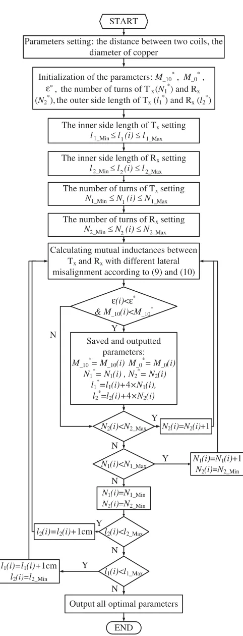
mutual inductance is proposed in order to obtain quasi-constant mutual inductance. The steps of the optimization method of quasi-constant mutual inductance are as follows:
(1) Parameters setting: VariableM10is the mutual inductance with Δ = 10 cm;M0 is the mutual
inductance with Δ = 0 cm; εis the rate of the change of mutual inductance with Δ = 10 cm along the
X orY direction, which is defined asε= (M0−M10)/M0. VariableDis set to 15 cm, and the diameter
of copper wire is 2 mm. Variable N1 is the number of turns of Tx; N1 is ranged from 4 to 8; N1 Min is
the minimum of N1;N1 Max is the maximum of N1. Variable N2 is the number of turns of Rx; N2 is
ranged from 4 to 10; N2 Min is the minimum of N2; N2 Max is the maximum of N2. Variable l1 is the
inner side length of Tx, which is ranged from 0.4 m to 0.6 m;l1 Min is the minimum of l1; l1 Max is the
maximum ofl1. Variablel2 is the inner side length of Rx, which is ranged from 0.2 m to 0.3 m; l2 Min is
the minimum of l2; l2 Max is the maximum of l2. The change of the inner side length is 1 cm, and the
step of the number of turns is 1 turn.
(2) Calculation of the mutual inductance: the mutual inductance between Tx and Rx can be calculated by Eqs. (9) and (10).
(3) The principle of quasi-constant mutual inductance: ε∗ is the initial value of rate of the change of mutual inductance with Δ = 10 cm along the X or Y s direction, which is set to 0.05 [19]. It is regarded that the coil structure satisfies the principle of quasi-constant mutual inductance whenε < ε∗. (4) The principle of maximum mutual inductance: First, the result must satisfy the principle of quasi-constant mutual inductance. Secondly, parameters of each coil are saved, and the current mutual inductance assigns to M∗10 if the current mutual inductance is larger than that of setting value. In
contrast, parameters of each coil are not saved, and the current mutual inductance does not assign to
M∗10. Therefore, the value of the mutual inductance will become bigger and bigger. The initial value of
the mutual inductance M∗10 is set to 6.5µH. The larger the value of mutual inductance between coils
is, the higher the transmission efficiency and power become.
(5) Optimal parameters: The optimal parameters, including mutual inductance, ε, the number of turns, and side length can be obtained according to maximum mutual inductance satisfying the condition ofε < ε∗. The flowchart of the optimization method is shown in Fig. 4.
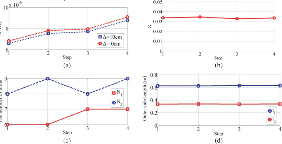
Figure 5(a) shows the mutual inductance with Δ = 10 cm and Δ = 0 cm. It can be seen that
(a) (b)
(c) (d)
the maximum value of M0 is 9.093µH, and the maximum value ofM10 is 8.787µH in the fourth step.
Fig. 5(b) shows that the rate of change of mutual inductanceεis about 0.034 in the fourth step, which is smaller than 0.05. Therefore, the solution of the fourth step conforms to the principle of quasi-constant mutual inductance and maximum mutual inductance. The parameters of each coil in the fourth step are selected as the optimal solution. Fig. 5(c) shows thatN1 is 7, andN2 is 9 in the fourth step. Fig. 5(d)
shows that the outer side lengths of Tx and Rx are 0.628 m and 0.336 m in the fourth step, respectively.
5. SIMULATION AND EXPERIMENTAL VERIFICATION 5.1. Experimental Setup
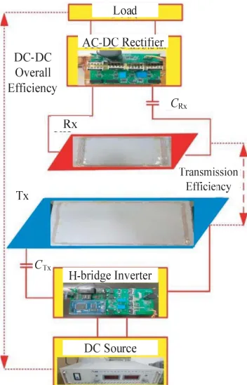
To evaluate the optimization method of quasi-constant mutual inductance, a WPT system of asymmetrical two-coil structure is built. The setup of the asymmetrical two-coil structure is shown in Fig. 6. The setup consists of a DC source, an H-bridge inverter, a full-bridge rectifier, Tx, Rx, and the load. The voltage of the DC source is ranged from 0 V to 400 V. The H-bridge inverter is composed
Figure 6. Setup of the asymmetrical two-coil. Table 1. Measured parameters of each coil.
Parameters Terms Values
L1/µH Self-inductance of Tx 100.00
L2/µH Self-inductance of Rx 69.74
CTx/nF Resonant capacitance of Tx 35.06
CRx/nF Resonant capacitance of Rx 50.27
R1/Ω Internal resistance of Tx 0.271
R2/Ω Internal resistance of Tx 0.149
of four Si C MOSFETs, and the type of the Si C MOSFET is C2M0080120D. Both Tx and Rx are the structure of planar spiral. The outer side lengths of Tx and Rx are 0.628 m and 0.336 m, respectively. The numbers of turns of Tx and Rx are 7 turns and 9 turns, respectively. The full-bridge rectifier consists of four diodes, and the type of the diode is D92. The load resistance is set to 3.0 Ω, and the original resonant frequency is set to 85 kHz. The self-inductance, resonant capacitance, and internal resistance of each coil are measured by an impedance analyzer. Table 1 shows measured parameters of each coil.
5.2. Test of Mutual Inductance
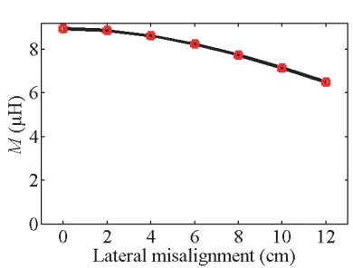
When the transmission distance between Tx and Rx is set to 15 cm; the misalignment is changed from 0 cm to 12 cm in theX direction; and the step is 2 cm. The mutual inductance between Tx and Rx can be tested by an impedance analyzer. The mutual inductances with different misalignments are shown in Fig. 7 and Table 2. In Fig. 7, the measured mutual inductances are nearly the same as the calculated and simulated results.
Table 2. MeasuredM and εwith D= 15 cm.
Misalignment M (µH) ε ε <0.05
0 cm 9.315 / /
10 cm 8.895 0.046 Yes
12 cm 8.712 0.065 No
MeasuredM andεare also shown in Table 2 withD= 15 cm. AllM are larger than 6.5µH, andε
is 0.046 with Δ = 10 cm, which meets the design requirements. The validity of the optimization method of quasi-constant mutual inductance is verified by the simulated and measured results.
When the outer side lengths of Tx and Rx are 0.336 m, and the numbers of turns of Tx and Rx are 9. Fig. 8 shows the simulated mutual inductance with different misalignments andD = 15 cm. It can be seen that the mutual inductance is equal to 8.95µH with Δ = 0 cm, and the mutual inductance is equal to 6.50µH with Δ = 10 cm. εis about 0.20 with Δ = 10 cm, which is much larger than 0.05. It is difficult to keep mutual inductance constant when Tx is the same as Rx in size.
When the transmission distance between Tx and Rx is set to 12 cm and the process of data-collection with D = 12 cm is the same as that with D = 15 cm, the results of mutual inductance with different
Figure 7. Mutual inductance with different
misalignments and D= 15 cm.
(a) (b)
Figure 9. Mutual inductances versus misalignments with different D. (a) Mutual inductances with
D= 12 cm. (b) Mutual inductances withD= 9 cm andD= 18 cm.
misalignments are shown in Fig. 9. In Fig. 9, the measured mutual inductances are nearly the same as the calculated and simulated results, which verify the validity of the proposed method.
Measured M and ε are shown in Table 3 with D = 12 cm. All M are larger than 6.5µH, and ε
are less than 0.05 with Δ = 10 cm and Δ = 12 cm, respectively. Mutual inductances with D = 9 cm and D= 18 cm are also measured. The measured results are shown in Fig. 9(b). WhenD= 9 cm, the mutual inductance with Δ = 0 cm is 11.36µH, and the mutual inductance with Δ = 12 cm is 11.42µH.
εis about 0.005 with Δ = 12 cm. When D= 18 cm, the mutual inductance with Δ = 0 cm is 7.88µH, and the mutual inductance with Δ = 12 cm is 7.34µH.εis about 0.069 with Δ = 12 cm. Compared with the mutual inductance results at different misalignments and transmission distances, it can be seen that the mutual inductance is more constant with D= 9 cm. Based on the above results, some conclusions can be drawn as follows: 1) under the same misalignment, the transmission distance becomes small, andεgets small; 2) The mutual inductance is nearly constant when misalignment is changed from 0 cm to 10 cm with D≤15 cm.
Table 3. MeasuredM and εwith D= 12 cm.
Misalignment M (µH) ε ε <0.05
0 cm 10.367 / /
10 cm 10.212 0.015 Yes
12 cm 10.067 0.029 Yes
5.3. Output Voltage and Efficiency
According to the parameters in Table 1, the transmission efficiency can be obtained with the help of MATLAB, as shown in Fig. 10. The transmission efficiency is nearly 90% with different misalignments. The measured results are not given in this paper because the output voltage of the H-inverter is a square wave, which is not convenient to be tested.
Figure 10. Simulation results of the transfer efficiency with lateral misalignments.
Figure 11. Output voltage with different lateral misalignments.
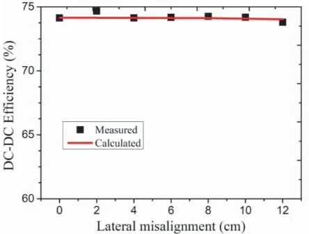
Figure 12. DC-DC efficiency at different lateral misalignments.
the load with different misalignments. As shown in Fig. 12, the overall efficiency of the DC-DC can be obtained from the results, which are almost 74% with different misalignments. The misalignment of in the X direction can be achieved at 10 cm, and the misalignment of X direction is the same as that of Y direction. According to SAE J2954 standard, the misalignment in X direction is 10 cm, and the misalignment in Y direction is 7.5 cm. Therefore, the misalignments in both X and Y directions meet SAE J2954 standard by using the structure of asymmetric two-coil, and the proposed method can be applied to wireless charging system of electric vehicles.
6. CONCLUSION
significance for the design of quasi-constant mutual inductance in the WPT system. However, the effect of the magnetic cores on the mutual inductance is not considered. We will further study quasi-constant mutual inductance of asymmetrical coils with magnetic cores in the future.
ACKNOWLEDGMENT
This work was supported in part by the National Natural Science Foundation of China under Grant 51377001, in part by the Hunan Provincial Department of Education under Grant 17C0469, in part by Hunan Provincial Natural Science Foundation of China under Grant 2018JJ3127 and 2019JJ60055, in part by Zhuzhou City Natural Science Foundation of China.
REFERENCES
1. Huang, X. L., W. Wang, and L. L. Tan, “Technical progress and application development of magnetic coupling resonant wireless power transfer,”Automatic of Electric Power Systems, Vol. 41, No. 2, 2−14+141, 2017.
2. Li, S. Q. and C. C. Mi, “Wireless power transfer for electric vehicle applications,” IEEE Journal of Emerging and Selected Topics in Power Electronics, Vol. 3, No. 1, 4–17, 2015.
3. Zhu, W. J. and S. Y. Gao, “Wireless power supply method for multi-rail-based electric vehicles,” Automatic of Electric Power Systems, Vol. 40, No. 18, 97–101, 2016.
4. Li, H., J. Li, K. Wang, et al., “A maximum efficiency point tracking control scheme for wireless power transfer systems using magnetic resonant coupling,” IEEE Transactions on Power Electronics, Vol. 30, No. 7, 3998–4008, 2015.
5. Fang, Z. J., J. H. Wang, S. X. Duan, et al., “Control of an LLC resonant converter using load feedback linearization,” IEEE Transactions on Power Electronics, Vol. 33, No. 1, 887–898, 2018. 6. Shu, X. J. and B. Zhang, “A fractional-order method to reduce the resonant frequency of
integer-order wireless power transmission system,”Transactions of China Electrotechnical Society, Vol. 18, 83–89, 2017.
7. Xu, G. Z., C. X. Li, J. Zhao, et al., “Electromagnetic environment safety study of wireless electric vehicle charging,”Transactions of China Electrotechnical Society, Vol. 22, 152–157, 2017.
8. Li, Y., Y. X. Zhang, Q. X. Yang, et al., “Analysis and experimental validation on maximum power and efficiency in wireless power transfer via coupled magnetic resonances,” Transactions of China Electrotechnical Society, Vol. 31, No. 2, 18–24, 2016.
9. Zhao, J. B., T. Cai, S. X. Duan, et al., “A T-type high misalignment tolerant compensated topology for sectional track-based dynamic wireless power transmission system,” Transactions of China Electrotechnical Society, Vol. 32, No. 18, 1–7, 2017.
10. Sample, A. P., B. H. Waters, S. T. Wisdom, et al., “Enabling seamless wireless power delivery in dynamic environments,”Proceedings of the IEEE, Vol. 101, No. 4, 1343–1358, 2013.
11. Xia, C. Y., S. Y. Ren, R. Chen, et al., “Inductive power and signal synchronous transmission based on parallel paths of fundamental wave and harmonic wave,”Automatic of Electric Power Systems, Vol. 42, No. 3, 1–7, 2018.
12. Choi, S. Y., B. W. Gu, S. Y. Jeong, et al., “Advances in wireless power transfer systems for roadway-powered electric vehicles,” IEEE Journal of Emerging and Selected Topics in Power Electronics, Vol. 3, No. 1, 18–36, 2015.
13. Jow, U. M. and M. Ghovanloo, “Geometrical design of a scalable overlapping planar spiral coil array to generate a homogeneous magnetic field,”IEEE Transactions on Magnetics, Vol. 49, No. 4, 2933–2945, 2013.
14. Waffenschmidt, E., “Homogeneous magnetic coupling for free positioning in an inductive wireless power system,”IEEE Journal of Emerging and Selected Topics in Power Electronics, Vol. 3, No. 1, 226–233, 2015.
16. Lu, F., H. Zhang, H. Hofmann, et al., “A dynamic charging system with reduced output power pulsation for electric vehicles,”IEEE Transactions on Industrial Electronics, Vol. 63, No. 8, 6580– 6590, 2016.
17. Kim, J., H. Son, D. Kim, et al., “Efficiency of magnetic resonance WPT with two off-axis self-resonators,”2011 IEEE MTT-S International Microwave Workshop Series on Innovative Wireless Power Transmission: Technologies, Systems, and Applications, 127–130, 2011.
18. Koledintseva, M. Y., J. L. Drewniak, T. P. van Doren, D. J. Pommerenke, M. Cocchini, and D. M. Hockanson, “Mutual external inductance in stripline structures,” Progress In Electromagnetics Research, Vol. 80, 349–368, 2008.