Interference Suppression Algorithm Based on Analog Circuits
Combined with Transform Algorithm in ELF Communication
Chunteng Li1, Yuzhong Jiang1, *, Fangjun Liu2, and Tingting Jiang3
Abstract—In order to effectively improve the communication quality in the extremely-low frequency (ELF) communication, a whole model of analog circuits and transform domain algorithm is constructed. Analog circuits include a pair of magnetic antennas, an amplifier and a group of filters. The distributed capacitance of the magnetic antenna is effectively reduced by the segmented winding method. Analog circuits used to amplify and filter received signal are designed. Besides, a magnetic sensor with high sensitivity is produced. The Karhunen-Lo`eve transform (KLT) algorithm applied to the field of interference suppression is deduced in detail. The transform successfully passes the received signal along the basis vector in sub-band, but the interference signal along the vector is attenuated. Therefore, the problem of an optimal filter is converted into the solution of transform factor for each sub-band. Then the relationship between the KLT transform and the time domain algorithm in the interference suppression problem is given. Based on the KLT algorithm, Fourier transform (FT) that makes the correlation matrices of the received signal diagonalized approximately is applied to the interference suppression algorithm. Based on the deduction results, the final optimal filter expressions are basically the same as the KLT algorithm. Finally, the experiments are carried out by using the simulated signal and real collected data in the laboratory, respectively. The schematic diagram of the real collected device is presented. The experimental result shows that, no matter the analog signal or the real collected data, the proposed algorithm can effectively suppress the interference. For the simulation, the performance of KLT algorithm is basically same as that of FT algorithm, but KLT algorithm is obviously better than FT algorithm for real collected data.
1. INTRODUCTION
ELF communication [1] has the characteristics of small attenuation, stable and reliable signal transmission and strong anti-interference ability in the sea water, and can solve the problem of long-distance and deep communication. ELF communication is almost all-weather, full space for reliable communication, which has rather prominent capabilities of hiding communication. However, the radiation efficiency of antenna in ELF communication is very low. The received signal is also facing strong background noise, so signal-to-noise ratio in ELF communication is very low. Some existing communication technologies can no longer meet the requirement of ELF communication. In order to improve the reliability of communication, the two aspects can be considered. It means increasing transmission power and adopting advanced signal enhancement technologies. The cost of former method is very high, and the effect is not obvious. Therefore, this paper enhances the desired signal from the latter, including two aspects of analog circuits design and the interference suppression algorithm.
Received 27 April 2018, Accepted 28 June 2018, Scheduled 24 July 2018 * Corresponding author: Yuzhong Jiang ([email protected]).
1 College of Electronic Engineering, Naval University of Engineering, Wuhan 430033, China. 2 Yunnan Nationalities University,
Given that the received signal in ELF communication is very weak, the ELF magnetic antenna with high sensitivity must be designed in order to effectively detect the desired signal. Yan et al. [2] proposed two different optimization schemes in consideration of the volume of the coil and magnetic core. Coillot et al. [3] optimized inductive magnetometer by adopting ferromagnetic cores with different shapes. Besides, Shao et al. used high-resistivity laminated magnetic cores and magnetic flux collectors on both sides of the magnetic core to increase the effective area and the effective permeability of the magnetic core so as to improve the sensitivity of the sensor, developing magnetic sensors with a wide range of frequency [4].
In this paper, starting from the principle of magnetism measuring of inductive magnetic sensor, magnetic core material with higher relative permeability is selected to produce the magnetic antenna with high sensitivity. In order to effectively increase the amplitude of the received signal and prevent the quantization noise from affecting the performance of the receiver, an integrated operational amplifier with low power consumption and low noise is designed and manufactured as the preamplifier of the magnetic sensor.
In terms of the interference suppression algorithm, there are many types of algorithms [5–7] based on the number of channels used, the mixed method of noise and signal, the statistical relationship between noise and signal, and the signal processing domain. The traditional algorithms mainly include matched filter [8], wavelet transform [9], etc. The term interference in this paper is widely accepted as additive noise that is statistically independent of the desired signal. The optimal filter can be directly designed in the time domain [10], but it often requires a large amount of computation, so techniques in the transform domain are generally accepted because each sub-band that refers to the desired signal component along each base vector of transform can be processed individually. Therefore, the problem of the optimal filter is converted into solving the transform factor for each sub-band. KLT is widely used in image recognition [11] and speech signal enhancement [12]. In this paper, KLT algorithm is applied to the ELF communication. At present, no application of this algorithm has been found yet. The transform projects the received signal and interference into different subspaces respectively, and the interference statistics can then be estimated from the interference subspace without desired signal. These statistics can be used to clean the received signal subspace subsequently, thereby restoring the desired signal. Furthermore, inspired by the KLT algorithm, the commonly used FT algorithm [13] is also applied to the ELF communication, and some interference suppression effect has been achieved.
2. MATERIAL AND METHODS
The model of proposed algorithm based on analog circuits and transform domain algorithm is shown in Fig. 1. In view of very weak ELF desired signal, the optimization design of the magnetic antenna effectively reduces the distributed capacitance of the magnetic antenna and improves the sensitivity of the magnetic antenna. Given the strong 50 Hz and its harmonic interference mixed in the ELF desired signal, the analog circuits are properly designed, which effectively suppress the out-of-band interference. After the process in analog domain is completed, the conversion of the signal from the analog domain to the digital domain is achieved by the data acquisition unit NI-cDAQ9184 produced by National
Instruments. The collected data are separately processed in each sub-band by using the transform domain algorithm, and optimal transform coefficients are chosen to achieve interference suppression and recover the desired signal. Finally, a reasonable evaluation index is established to evaluate the proposed algorithm.
2.1. Magnetic Antennas
Magnetic antenna is mainly composed of induction coil and magnetic core. The quality of magnetic antenna has great influence on the performance of magnetic sensor. Due to the limited experimental environment, the noise floor of the magnetic antenna cannot be measured; therefore, the sensitivity of the magnetic antenna can only be qualitatively analyzed. The magnetic core used in this paper is a nanocrystalline alloy material, which is a new type of soft magnetic material with high permeability and low magnetic core loss. At the same time, the material has better performance and lower price than other metal soft magnetic materials and has gradually replaced silicon steel.
When the magnetic antenna is produced, the motor and reducer are combined as a winding machine, which can achieve automatic winding instead of the original manual winding, and the counter is installed on winding machine to record the number of turns automatically. The above method improved the winding efficiency and the accuracy of the number of turns recorded. In addition, the segment winding using acrylic clapboard is adopted. In order to make the winding coil firmly fixed on the core, the produced antennas are soaked in the varnish for a period of time. By measuring the self-resonant frequency of the antenna, it is found that this segment winding method can reduce the distributed capacitance of the antenna by an order of magnitude, compared to the original direct winding method, which is equivalent to improving the passband quality factor.
2.2. Analog Circuits
The role of the preamplifier is to amplify the front weak signal, and the key design is to reduce the noise voltage. The amplifier used in this paper is AD797 chips. By referring to the instruction of the chip and noise model of the simulation, it is found that the input and output noises of the chip are very low at frequency below 1 kHz. Therefore, the chip is well suited as a preamplifier.
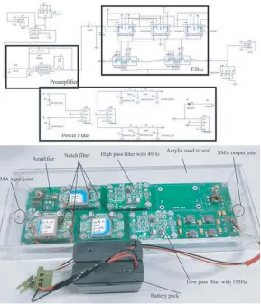
The filter circuits including two types of notch filters, a low-pass filter and a high-pass filter are mainly used to filter out different types of interferences. Although the switched capacitor filter has better performance, the filter can lead to higher noise. Therefore, this paper adopts the active filter. In view of the fact that the 50 Hz interference and its odd harmonics in the atmospheric noise are much larger than the even harmonics, the two types of notch filters, 50 Hz and 150 Hz, are used. The designed notch filter can theoretically have the notch depth up to 40 dB and can be adjusted by the potentiometer, but the measured result showed that notch filter did not reach the theoretical value in practice due to center frequency offset. Although the offset is only a few percent of Hz, notch filter circuit debugging is quite difficult. Therefore, this paper uses a two-stage notch filters cascade instead of circuit debugging. For a 195 Hz low-pass and a 40 Hz high-pass filter, the paper adopts a fourth-order Butterworth filter. The theoretical attenuation of this kind of filter is −80 dB/decade. To avoid the introduction of 50 Hz interference, the above filters are powered by 6 V battery pack. Besides, the designed circuit board frame is sealed up by acrylic sheet and glass plastic and reserves two holes on left and right ends of the circuit board to install an SMA connector for input and output signal. The final designed analog circuits board are shown in Fig. 2.
2.3. Signal Model
The interference suppression problem considered in this paper is to recover the desired signal x(k) with zero mean from the received signal by sensors. The signal model can be written as
Figure 2. The schematic and physical structure of designed analog circuits.
Assuming that the data are processed by groups with the length of L, Equation (1) can be changed in vector form
y(k) =x(k) +n(k) (2)
where y(k) = [y(k), y(k−1), . . . , y(k−L+ 1)]T, T is the transpose operator. The form of x(k), and
n(k) is defined similarly withy(k). The correlation matrix of the noisy signal is expressed as
Ryy(k) =Rxx(k) +Rnn(k) (3) where Ryy(k) = Ey(k)yT(k) is the correlation matrix of y(k) with L×L dimension at time k;
Rxx(k) = Ex(k)xT(k) and Rnn(k) = En(k)nT(k) are similar to Ryy(k); E{·} represents the mathematical expectation. For convenience of presentation, in the rest of this paper, the time index in correlation matrix will be omitted.
The problem in this paper is how to estimate the desired signal from the received signal, if linear transformation is applied to the problem, which can be solved as
xe(k) =W y(k) =W(x(k) +n(k)) =xw(k) +nw(k) (4) where W is the filter matrix with L×L dimension, xw(k) the filtered desired signal, and nw(k) the residual interference. Therefore, the interference suppression problem becomes to find the optimal filter which can make the desired signal basically undistorted and the interference attenuated as much as possible.
2.4. Performance Index
power of desired signal to the power of interference signal. However, the index can be simplified in order to meet the need in practice. The simplified SIR is defined as the ratio of the spectrum of desired signal to the spectrum of interference signal. And the SIR is expressed as
SIR (dB) =Sx(dB)−Sn(dB) (5)
whereSx is the spectrum of desired signal in log-domain, andSn is the spectrum of interference signal at certain frequency in log-domain.
2.5. KLT Algorithm
One of the most beneficial aspects of the KLT is its potential to reduce the dimensionality of the vector. Below, KLT algorithm will be directly applied to achieve interference suppression by estimating the KLT coefficients of the desired signal in each sub-band.
The correlation matrixRyy is diagonalized as
UTR
yyU =D (6)
where U = [u1, u2, . . . , uL] represents L×L dimension orthogonal matrix composed with eigenvectors ofRyy, andD= diag{δ1, δ2, . . . , δL} represents the diagonal matrix composed with eigenvalues ofRyy. The vector y(k) can be written as
y(k) = L
l=1
αy(k, ul)ul (7)
where
αy(k, ul) =ulTy(k), l= 1,2, . . . , L (8) represents the coefficients of KLT. The representation of the random vector described by Eqs. (7) and (8) is the KLT where Eqs. (7) and (8) are respectively synthesis part and analysis part [12].
Given thaty(k) is the received vector with zero mean andU is orthogonal matrix,
E{αy(k, ul)}= 0, l= 1,2, . . . , L
E{αy(k, ui)αy(k, uj)}= δ
i, i=j 0, i=j
(9)
According to Equation (2), Equation (8) is written as
αy(k, ul) =ulTy(k) =ulT(x(k) +n(k)) =αx(k, ul) +αn(k, ul), l= 1,2, . . . , L (10) From Equation (10), the KLT coefficients along base vector are uncorrelated with those along other base vectors; therefore, KLT coefficients along different base vectors can be independently estimated without considering the influence on each other. Obviously, the interference suppression problem in KLT algorithm is to recover αx(k, ul) by multiplying αy(k, ul) with a scalar filter wl, and it can be expressed as
ˆ
αx(k, ul) =wlαy(k, ul) =wl(αx(k, ul) +αn(k, ul)), l= 1,2, . . . , L (11)
Therefore, the error signal in KLT is defined as
e(k, ul) =αx(k, ul)−αˆx(k, ul) =αx(k, ul)−wlαy(k, ul), l= 1,2, . . . , L (12) The mean square error (MSE) criterion is adopted, and the cost function is defined as
J(ul) =E
|e(k, ul)|2
=E
|αx(k, ul)−wlαy(k, ul)|2
(13)
The optimal filter is designed by setting the derivative to zero, which means ∂J(ul)/∂wl = 0; therefore, it is expressed as
wl= E{αx(k, ul)αy(k, ul)}
E{αy(k, ul)αy(k, ul)} =
E{αy(k, ul)αy(k, ul)} −E{αn(k, ul)αn(k, ul)}
According to Equation (9),E{αn(k, ui)αn(k, uj)} is written as
E{αn(k, ui)αn(k, uj)}=
uiTRnnui, i=j
0, i=j (15)
Substituting Equation (15) into (14), the optimal filter can be written as
wl= δl−ul TR
nnul
δl , l= 1,2, . . . , L (16)
Below, the relation between KLT and time domain will be shown. In time domain, the estimated desired signal can be expressed as
xe(k) = L
l=1 ˆ
αx(k, ul)ul = L
l=1
wlulTy(k)ul = L
l=1
wlululTy(k) =W(U)y(k) (17)
where W(U) = Udiag{w}UT is the optimal filter with L × L dimension in time domain, and
w= [w1, w2, . . . , wL] corresponds to the optimal filter in KLT.
2.6. Fourier Domain Algorithm
The interference suppression in KLT algorithm is to diagonalize the correlation matrixRyy of received signal, and Ryy is the Toeplitz matrix. Therefore, a new transform in Fourier domain can be proposed to diagonalize the correlation matrix Ryy approximately. The method adopted in Fourier domain is basically the same as that in KLT that makes interference signal along base vector attenuated as much as possible without signal distortion.
The unitary matrix chosen in Fourier domain is defined as F = [f1, f2, . . . , fL], where
fl= √1
L
1, ejωl, . . . , ejωl(L−1) T, ω
l= 2π(l−1)/L, l= 1,2, . . . , L (18)
Assuming that received signal is filtered by g(fl) = [g1(fl), g2(fl), . . . , gL(fl)]T, the signal along
fl vector has no attenuation, but the signal along other vectors is largely attenuated. It means that
flHg(fl) = 1, where H represents the conjugate transpose of the vector. The spectrum pyy(fl) of received signal along base vector fl is defined as
pyy(fl) =gH(fl)Ryyg(fl) (19) Therefore, appropriate cost function needs to be chosen to get g(fl). The cost function is defined as
J(g(fl)) =gH(fl)Ryy1/2g(fl) +λ1−flHg(fl) (20)
whereRyy1/2 is the square root of correlation matrixRyy, andλis the Lagrange factor. By minimizing the cost function, the solution of Equation (20) is expressed as
g(fl) = λ 2Ryy
−1/2f
l (21)
Substituting the constraintflHg(fl) = 1 into Equation (21),λ= 2/(flHRyy−1/2fl), so the solution can be expressed as
g(fl) = Ryy
−1/2f l
flHRyy−1/2f l
(22)
It is similar to Equation (8), and the coefficients in Fourier transform are defined as
βy(k, fl) =gH(fl)y(k), l= 1,2, . . . , L (23)
Eβy(k, ui)βyH(k, uj)and Eβn(k, ui)βnH(k, uj)are respectively deduced as
Eβy(k, ui)βyH(k, uj)= p
yy(fl), i=j
0, i=j , E
βn(k, ui)βnH(k, uj)= p
nn(fl), i=j
where the definition of pnn(fl) is similar to pyy(fl), and it means pnn(fl) =gH(fl)Rnng(fl). Therefore, according to Equation (14), the optimal filter can be written as
wl= 1− pnn(fl)
pyy(fl), l= 1,2, . . . , L (25)
From Equations (16) and (25), the form of the optimal filter in Fourier transform is basically same as that in KLT.
3. EXPERIMENTAL RESULTS AND DISCUSSION
3.1. Ideal Signal Simulation
As the atmospheric noise contains strong 50 Hz interference and its harmonic components, a set of 50 Hz and its harmonic interferences are adopted in simulation, and MSK signal with 138 Hz center frequency and a bandwidth of 20 Hz is set as another strong interference signal. The desired signal is set to the single frequency signal with 130 Hz. The noise is Gaussian white noise. For 50 Hz interference, the input SIR is set to −14 dB, and for MSK interference, the input SIR ratio is set to −5 dB. In order to estimate the correlation matrices respectively, two channels are adopted. One channel is used to receive the mixed signal, and the other channel only receives the interference signal. The sampling frequency is set to 2 kHz, and the number of data points is set to 20000. By a large number of simulations, the filter length Lis finally set to 20. In view of the limited space of the paper, only the simulation results under this group of parameters are given in Fig. 3.
As can be seen from Fig. 3, both KLT and FT algorithms can effectively suppress the interference, and KLT algorithm is slightly better than the FT algorithm. For the KLT algorithm, the output SIR ratios of the signal to 50 Hz interference and to MSK interference are respectively 19 dB and 21 dB. For the FT algorithm, the output SIR ratios for the above interferences are 15 dB and 21 dB respectively. Although the noise floor is increased, the proposed algorithm can improve the SIR gain, and the power spectrum of the output signal is far above the noise floor. Therefore, the proposed algorithm can achieve ELF communication effectively.
3.2. Experiment Results
In the subsection, analog signal simulation is used, and the simulation environment is relatively ideal. However, the real environment changes at any time. It can be seen from the derivation of the previous formulas that the correlation matrices of the received signal and interference are crucial to the proposed algorithm. Therefore, in order to avoid the estimate with large error leading to inaccurate experiment results, the receiver signal and interference signal are constructed as
Y
(k) =yT(k−p+ 1);. . .;yT(k−1);yT(k)p×L
V(k) =nT(k−p+ 1);. . .;nT(k−1);nT(k)p×L (26)
wherep represents the selected data groups, and different algorithms have different choice. Since Y(k) and V(k) are both Toeplitz matrices, the method that Ryy and Rnn are respectively estimated by
YT(k)Y(k)/p andVT(k)V(k)/p is reasonable and effective.
Figure 3. The simulation results of ideal signal.
Figure 4. The schematic and physical structure of data acquisition platform.
Through a large number of experiments, finally, the filter lengthLis set to 20. The number of data groupsp selected is set to 200. Other parameters are set basically same as the ideal signal simulation. The experimental results are shown in Fig. 5.
Figure 5. The experimental results of real collected data in the laboratory.
software is written to convert the *.TDMS format into *.XLSX. As long as data storage location is imported into program, the above format conversion can be achieved.
It can be seen from Fig. 5 that for the real atmospheric noise, analog circuits effectively suppress the 50 Hz interference and its harmonic components, and the proposed algorithm achieves better interference suppression effect. For the KLT algorithm, the input SIR ratio of the signal to the MSK is about−12 dB, and the output SIR ratio is 15 dB. For the FT algorithm, the output SIR ratio is 5 dB. The noise floor processed by the KLT algorithm is slightly increased, while that processed by the FT algorithm is significantly increased. Obviously, for the actual atmospheric noise, the performance of KLT algorithm is obviously better than that of FT algorithm, which may be because the constructed FT matrix does not well diagonalize the correlation matrix of the received signal. It can also be seen from Fig. 5 that although the interference at 250 Hz is still strong, it is far lower than the signal power spectrum and does not affect the communication quality of ELF communication.
4. CONCLUSIONS
while KLT algorithm is obviously better than FT algorithm for real collected data. Although both algorithms can raise the noise floor to some extent, the interference suppression effect is obvious. The power spectrum of the desired signal processed by the analog circuits and the proposed algorithm is higher than all types of interference signals, which can effectively improve the reliability of the ELF communication.
REFERENCES
1. Ying, W., Y. Jiang, and Y. Liu, “A blind detector for Rayleigh flat-fading channels with non-Gaussian interference via the particle learning algorithm,” AEU-International Journal of Electronics and Communications, Vol. 67, No. 12, 1068–1071, 2013.
2. Yan, B., W. Zhu, L. Liu, et al., “An optimization method for induction magnetometer of 0.1 mHz to 1 kHz,”IEEE Trans. Magn., Vol. 94, No. 10, 5294–5300, 2013.
3. Coillot, C., J. Moutoussamy, M. Boda, et al., “New ferromagnetic core shapes for induction sensors,”J. Sensors Sensor Syst., Vol. 3, 1–8, 2014.
4. Shao, Y., D. Cheng, and Y. Wang, “Research on high sensitivity inductive magnetic sensor,”
Chinese Journal of Scientific Instrucment, Vol. 33, No. 2, 345–355, 2012.
5. Van Veen, B. and K. Buckley, “Beamforming: A versatile approach to spatial filtering,” IEEE ASSP Mag., Vol. 5, No. 2, 4–24, 1988.
6. Li, P. and K. B. Letaief, “A blind RAKE receiver with robust multiuser interference cancelation for DS/CDMA communications,” IEEE Transactions on Communications, Vol. 55, No. 9, 1793–1801, 2009.
7. Masmoudi, A. and T. Le-Ngoc, “Channel estimation and self-interference cancelation in full-duplex communication systems,” IEEE Transactions on Vehicular Technology, Vol. 66, No. 1, 321–334, 2017.
8. Jamali, V., A. Ahmadzadeh, and R. Schober, “On the design of matched filters for molecule counting receivers,” IEEE Communications Letters, Vol. 21, No. 8, 1711–1714, 2017.
9. Narkedamilly, L., V. P. Evani, and S. K. Samayamantula, “Discrete multiwavelet-based video watermarking scheme using SURF,” ETRI Journal, Vol. 37, No. 3, 595–605, 2015.
10. Doclo, S. and M. Moonen, “GSVD-based optimal filtering for single and multimicrophone speech enhancement,”IEEE Transactions on Signal Processing, Vol. 50, No. 9, 2230–2244, 2002.
11. Kittler, J. and P. C. Young, “A new approach to feature selection based on the Karhunen-Loeve expansion,” Pattern Recognition, Vol. 5, No. 4, 335–352, 1973.
12. Chen, J., J. Benesty, and Y. Huang, “Study of the noise-reduction problem in the Karhunen-Lo`eve expansion domain,”IEEE Transactions on Audio, Speech, and Language Processing, Vol. 17, No. 4, 787–802, 2009.