Design of Compact Microstrip Antenna Array
with Decoupling Network
You-Bao Wang1, *, Shun Xiao1, Bo Zhang2, and Ye Wei1
Abstract—An innovative decoupling microstrip antenna array is designed. In the design approach, a decoupling and folding microstrip circuit is proposed instead of lumped element circuit, so that the circuit structure is simplified, and the antenna array is fabricated easily in print. Inverted L shape is used as its radiator in order that the size of the antenna array is miniaturized. Stepped impedance transformer is added for the sake of weakening ports reflection. The simulation and measurement results show that the proposed antenna array works at 2.45 GHz, and its reflection coefficient and isolation are both below−20 dB in the working band (2.4 GHz–2.48 GHz). The proposed antenna array has patterns close to omnidirectional.
1. INTRODUCTION
With the increasing demands on data transmission rate and transmission quality for modern wireless communication systems, many advanced technologies have been developed to confront the challenges. According to Shannon capacity limit[1], the channel capacity of a traditional wireless communication system, with single-input single-output (SISO), multiple-input single-output (MISO) or single-input multiple-output (SIMO), cannot be added. The techniques cannot satisfy the growing demand for data transmission. In order to enhance wireless communication transmission rate, input multiple-output (MIMO) is taken as a breakthrough technology [2]. With MIMO technology, multiple antennas are used in the systems of transmitter and receiver at the same time, and multiple parallel space channel are created when the multi-path fading between sending and receiving antennas tends to be independent under a rich multi-path wireless component. The difference from traditional technology is that indoor multi-path propagation can be utilized to improve signal quality and reliability, and the capacity of communication system and transmission rate are increased exponentially, without sacrificing the bandwidth [3]. In MIMO system, the terminal antenna selection should depend on the integrated effect of antenna gain, direction diagram, matching feature, easy processing, low profile, small volume, light quality and other factors. For example, omnidirectional antenna is very suitable for MIMO system application. However, when the multi-antenna technology is applied to small MIMO mobile terminal equipment, there will be mutual coupling between antenna units. It is well known that mutual coupling degrades the performance of array signal-processing algorithms [4, 5]. To avoid the coupling, the spacing between the antenna array units is usually designed to be greater than half wavelength [6, 7]. Because of the size limitation of mobile communication devices, it is difficult to have many antenna units in a mobile communication system [8]. In the existing research, usual decoupling methods are to modify the ground structure decoupling [9, 10], adopt the resonance structure decoupling [11, 12], use the current neutralization technology decoupling [13], etc. In recent years, the method of joining the decoupling
Received 22 March 2016, Accepted 11 May 2016, Scheduled 18 May 2016 * Corresponding author: You-Bao Wang ([email protected]).
1 Jiangsu Key Laboratory of Meteorological Observation and Information Processing, and Jiangsu Technology & Engineering Center
network between antennas has attracted much attention [14, 15]. In papers [14, 15], lumped elements are used in decoupling network. Nevertheless, they are sensitive and not easy to be debugged. At the same time, it is difficult to achieve large-scale integrated production.
In this article, a microstrip circuit is used instead of a traditional lumped components circuit. So the whole structure is able to be made by printing. Meanwhile, inverted L shape is used for its radiator to get smaller antenna array system. In addition, port matching is reached at a very high degree by the use of stepped impedance matcher. The antenna’s reflection coefficient and isolation are both below−20 dB in the working band (2.4 GHz–2.48 GHz), which are obtained by both the simulation and measurement, indicate that the proposed antenna array is a good candidate for mobile terminal equipments.
2. DESIGN PRINCIPLES
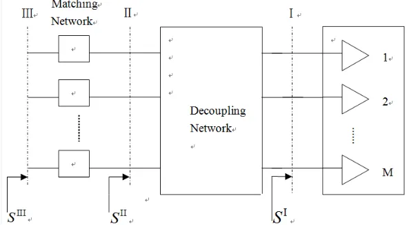
Figure 1 shows that the MIMO system consists of a decoupling network with M antenna units. As illustrated by Fig. 1, the three dotted lines marked with I, II, III represent three end planes toward the antenna array. Generally, the multiple antenna system is matched at the end plane I toward the antenna array. Then the diagonal elements of the corresponding scattering matrix SI should be zero, namely SiiI = 0, i= 1,2,· · · , M. Because the close distance between the antenna units creates strong mutual coupling between them, the off-diagonal elements of matrix SI are not equal to zero, namely
SI
ij = 0,i=j, and i,j= 1,2,· · · , M. In order to reduce the mutual coupling, a decoupling network is
added into the multiple antenna systems as shown in Fig. 1. It is equivalent to make the off-diagonal elements of the scattering matrix SII at the end plane II equal zero, namely SijII = 0, i = j, and i,
j = 1,2,· · · , M. But the zero value diagonal elements in SII are not able to be ensured generally at the same time, namely SiiII = 0, i= 1,2,· · · , M. The ports at the end plane II are not fully matched. Therefore, the matching network after the end plane II in Fig. 1 is appended so as to let the diagonal elements of the scattering matrix SIII be zero. By now, the decoupling and matching of the antenna
array are implemented at the end plane III. All elements of the corresponding scattering matrixSIIIare
zero, namelySIII
ij = 0, i, j= 1,2,· · ·M. It should be pointed out that the key technology is the design
of the decoupling network. The corresponding characteristics are described with the above scattering matrixSII. Obviously it is not intuitive to give the characteristics of the microstrip circuit bySII. It is needed to convert the scattering matrixSII into the admittance matrixYII, accordingly YijII = 0,i=j, and i, j = 1,2,· · · , M. The reason can be explained with the following example of an antenna array with two units.
In Fig. 1, assume that when the antenna array is composed of two antenna units, the corresponding
scattering matrix SII can be written as:
SII=
SII 11 S12II SII
21 S22II
(1)
And the admittance matrix YII can be defined as follows:
YII =
YII
11 Y12II YII
21 Y22II
(2)
The off-diagonal elements relation betweenYII and SII can be written [16] as follows
YII
12 =Y0 −
2S12II
1 +SII
11 1 +S22II
−SII 12S21II
(3)
YII
21 =Y0 −
2S21II
1 +S11II 1 +S22II−S12IIS21II (4)
where Y0 denotes the characteristic of the microstrip line admittance. It is clear that there are YII
12 = Y21II = 0 when S12II = S21II = 0. According to the result, the off-diagonal elements admittance
values of the matrix YI, which are at the end plane I watching to the antenna array, are offset with the admittance values of the decoupling network. It implies that the design of the decoupling network provides very strong operational guidelines. In addition, because the decoupling among the antenna ports is done by admittance offset, the coupling problem handled by using microstrip network must be pure reactance characteristic.
The detailed explanation of the above decoupling principle can be found in [17, 20]. Here the decoupling means that the obtained signal from any antenna port is decoupled. Namely the coupled signal from space and the signal transmitted by the band-pass filter neutralize each other.
3. ANTENNA DESIGN
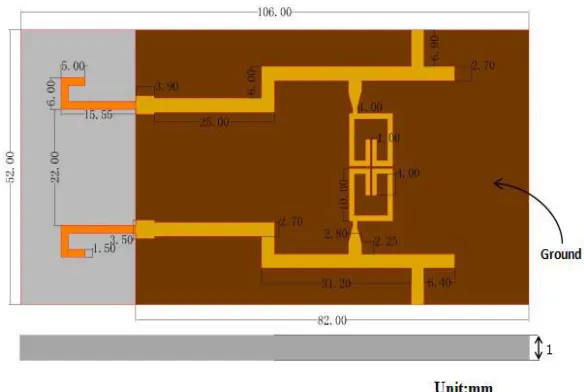
Based on above theories, the designed antenna array is shown in Fig. 2, which adopts PCB with a relative dielectric constant of 2.65 and size of 106 mm×52 mm×1 mm. The antenna operates at 2.45 GHz.
The ground plane with 82 mm×52 mm and the two reserved L as radiating elements are printed on the two sides of the PCB, respectively, as Fig. 2. The sizes of the antenna units and the decoupling
Figure 3. Antenna physical.
Figure 4. Simulated and measured return loss of the antenna port.
Figure 5. Simulation and measurement
isolations between the two ports.
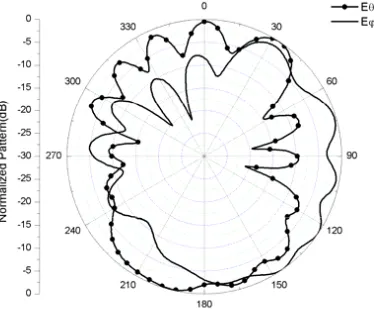
Figure 6. Measured radiation pattern of antenna unit 1 onXOY plane at 2.45 GHz.
network are marked in Fig. 2. In addition, stepped impedance transformer is used to enhance the match degree of the antenna ports.
Fig. 4, reflectivity. Due to structure symmetry, port 2 reflection coefficient is the same as that of port 1. The isolation level is shown in Fig. 5. Figs. 6, 7 and 8 show the measured far-field radiation patterns of XOY plane, Y OZ plane and XOZ plane when 2.45 GHz excitation signal is input from port 1 and 50 Ω matched load connected with port 2 in microwave dark room. Among them, θ means the angle between the XOZ (or Y OZ) plane projection component of position vector and Z-axis, and ϕ means the angle between XOY plane projection component of the position vector and X-axis. Also the 3D radiation pattern is given in Fig. 9 for understanding the antenna characteristic well.
According to the above curves (from Fig. 4 to Fig. 5), when the decoupling network is joined in the MIMO antenna array, the return loss and isolation degree are all less than −20 dB in the working frequency band (2.4 GHz to 2.48 GHz). A good antenna radiation in Y OZ plane is shown in Fig. 7. It is very important for the actual MIMO application that the antenna radiation takes place in all θ directions whenϕ= 90 degree. Due to the symmetry of the two antennas, the radiation pattern of unit 2 is the same as that of unit 1. So they have complementary characteristics in space. The good antenna performance of diversity is needed for MIMO antenna. The above design indicates that the coupling between the antenna units can be eliminated by adding the microstrip decoupling network, and multiple antennas can be placed in the narrow space at a mobile terminal.
Figure 7. Measured radiation pattern of antenna unit 1 onY OZ plane at 2.45 GHz.
Figure 8. Measured radiation pattern of antenna unit 1 onXOZ plane at 2.45 GHz.
4. CONCLUSIONS
A new microstrip antenna array is designed. In this design, a decoupling network of lumped components is replaced with that of microstrip so as to avoid the sensitivity of the lumped components debugging and the difficulties in making the antenna system. Meanwhile, the isolation degree between the closely spaced ports of the antenna array is enhanced, and the whole system can be fabricated. Also, according to the simulated and measured results, it can be seen that the MIMO antenna array has a high degree of isolation and low return loss. The design requirements are met. As a result, the compact microstrip type multiple antenna system has a certain application prospect.
ACKNOWLEDGMENT
This work was supported in part by the National Natural Science Foundation of China under Grant 2013g067 and by the Priority Academic Program Development of Jiangsu Higher Education Institutions.
REFERENCES
1. Shannon, C. E., “A mathematical theory of communication,” Bell System Technical Journal, Vol. 27, No. 3, 379–423, 1948.
2. Andersen, J. B., “Array gain and capacity for known random channels with multiple element arrays at both ends,” IEEE J. Select. Areas Commun., Vol. 18, 2172–2178, Nov. 2000.
3. Cui, S., Y. Liu, and W. Jiang, “Compact dual-band monopole antennas with high port isolation,”
Electronics Lett., Vol. 47, No. 10, 579–58, May 2011.
4. Lu, S., H. T. Hui, and M. Bialkowski, “Performance analysis of multiple-input multiple-output orthogonal frequency division multiplexing systems under the influence of antenna mutual coupling effect,” IET Microwaves, Antennas &Propagation, Vol. 3, No. 2, 288–295, March 2009.
5. Hui, H. S. and H. T. Lui, “Effective mutual coupling compensation for direction-of-arrival estimations using a new, accurate determination method for the receiving mutual impedance,”
Journal of Electromagnetic Waves &Applications, Vol. 24, 271–281, 2010.
6. Yeung, L. K. and Y. E. Wang, “Mode-based beamforming arrays for miniaturized platforms,”IEEE
Trans. Microwave Theory and Techniques, Vol. 57, No. 1, 45–52, Jan. 2009.
7. Xu, H., G. Wang, and M. Qi, “Hilbert-shaped magnetic waveguided metamaterials for electromagnetic coupling reduction of microstrip antenna array,”IEEE Trans. Magnetics, Vol. 49, No. 4, 1526–1529, Apr. 2013.
8. Yeung, L. K. and Y. E. Wang, “A decoupling technique for compact antenna arrays in handheld terminals,” IEEE Trans. Radio and Wireless Symposium (RWS), 80–83, New Orleans, LA, 2010. 9. Kim, I., W. J. Kim, Y. Kim, and Y. E. Kim, “Low-profile wideband MIMO antenna with
suppressing mutual coupling between two antennas,” Microwave and Optical Technology Lett., Vol. 50, No. 5, 1336–1339, 2008.
10. Luo, C. M., J. S. Hong, and L. L. Zhong, “Isolation enhancement of a very compact UWB-MIMO slot antenna with two defected ground structures,” IEEE Antennas and Wireless Propagation
Letters, Vol. 14, 1766–1769, Apr. 2015.
11. Zhu, J. and G. V. Eleftheriades, “A simple approach for reducing mutual coupling in two closely spaced metamaterial-inspired monopole antennas,” IEEE Antennas and Wireless Propagation
Letters, Vol. 9, No. 1, 379–382, 2010.
12. Dadashzadeh, G., A. Dadgarpour F. Jolani, and B. S. Virdee, “Mutual coupling suppression in closely spaced antennas,”IET Microwaves Antennas &Propagation, Vol. 5, No. 1, 113–125, 2011. 13. Park, S. and C. Jung, “Compact MIMO antenna with high isolation performance,”IET Electronics
letters, Vol. 46, No. 6, 390-391, 2010.
15. Tang, X., K. Mouthaan, and J. C. Coetzee, “Tunable decoupling and matching network for diversity enhancement of closely spaced antennas,” IEEE Antennas and Wireless Propagation
Letters, Vol. 11, 268–271, 2012.
16. Pozar, D M., Microwave Engineering, Wiley. com, 2009.
17. Zhao, L., L. K. Yeung, and K. L. Wu, “A novel second-order decoupling for two-element compact antenna arrays,”Microwave Conf., Asia-Pacific, 1172–1174, 2012.
18. Zhao, L., L. K. Yeung, and K. L. Wu, “A coupled resonator decoupling network for two-element compact antenna arrays in mobile terminals,” IEEE Trans. Antennas and Propagation, Vol. 62, No. 5, 2767–2776, May 2014.
19. Zhao, L. and K. L. Wu, “A dual-band coupled resonator decoupling network for two coupled antennas,”IEEE Trans. Antennas and Propagation, Vol. 63, No. 7, 2843–2850, Jul. 2015.