Improved Bucking Coil Design in Helicopter Transient
Electromagnetic System
Pan Xiao1, 2, *, Zongyang Shi1, 2, Xin Wu1, 2, and Guangyou Fang1
Abstract—The presence of the primary field in the helicopter transient electromagnetic system makes the dynamic range of the response signal so large that it is difficult to observe the secondary field. Therefore, a bucking coil is usually introduced to eliminate the primary field. However, in a traditional design, the size of the bucking coil increases with the size of the system, which makes the bucking coil hard to install, and opposite magnetic moment is large in huge systems. In this paper, a new bucking coil design for a helicopter transient electromagnetic system is proposed. Compared with the traditional design, the bucking coil diameter, total weight and total magnetic moment in two designs are calculated. The results show that the bucking coil we designed is more than 8 times smaller and 5 times lighter than that in the traditional design, which is easier for installation. The bucking moment impact is reduced to 0.03% of the total magnetic moment when the diameter of the transmitting coil increases to 35 m, which improves the efficiency of the system. Then we analyze the requirement of manufactory precision and installation accuracy for the bucking coil in our design to get the best bucking result.
1. INTRODUCTION
Helicopter transient electromagnetic (HTEM) system, with the advantage of high survey efficiency and lower cost, has been a more and more popular method in mineral exploration [1], environment investigation and unexploded material detection [2–4]. The transmitting coil and receiving coil are loaded by a helicopter, and the transmitting coil is used to create a primary time varying magnetic field, which causes eddy currents to flow in conductors. A secondary electromagnetic field is generated by these currents, and the electromotive force due to such a field can be measured by using the receiving coil [5]. Fig. 1 shows the working principle for a helicopter transient electromagnetic system.
As shown in Fig. 1, the receiving coil receives both the primary field and secondary field. The primary field is much bigger than secondary field. Due to being mixed with the primary field, the dynamic range of the HTEM receiving signal is usually up to 140 dB [6]. It is hard for the receiver to accurately record the secondary field, which contains abundant information of the underground. One of the famous methods to eliminate the primary field is using an additional coil, called bucking coil, to generate an electromagnetic field opposite to the primary field, in the receiving coil.
In the traditional design, the bucking coil lies between the transmitting coil and receiving coil, such as the VTEM systems [7]. Due to the limitation of the loading capability of the helicopter, the total weight of the system always plays an important role in the consideration of designing an HTEM system. With the increasing demand for detecting minerals in deep depth, the magnetic moment of HTEM system becomes bigger and bigger. The VTEM system, developed at about ten years ago, has a magnetic moment of 240 k Am2. When it turns to the VTEM Max system, its dipole moment is increased to 1.3 M Am2 [8]. However, the side effect appears with the increase of magnetic moment.
Received 19 July 2017, Accepted 14 September 2017, Scheduled 21 September 2017 * Corresponding author: Pan Xiao ([email protected]).
Figure 1. Working principle of the helicopter transient electromagnetic system.
It is known that increasing the diameter of transmitting coil is preferred to increasing its turns when increasing the moment, because the weight of the system grows slower. The bigger the transmitting coil is, the larger and heavier the bucking coil is and the more difficult is in mounting the bucking coil. A more solid supporting structure for the bucking coil is needed, and in turns, the additional weight makes the coil heavier. On the other hand, the bigger bucking coils means the larger opposite moment, which decreases the detecting ability of the system.
To reduce the side effect of the bucking coil, we propose a new design for the system. The size of the bucking coil in our design gets smaller when the transmitting coil is larger, which is better for a huge magnetic moment system.
2. COIL DESIGN IN AEM SYSTEM
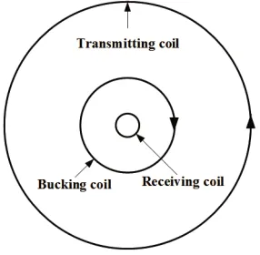
The HTEM systems, such as VTEM series, consist of three coils, i.e., transmitting coil, bucking coil and receiving coil. Their arrangement in the whole coil system is shown in the Fig. 2.
Figure 2. Coils arrangement for the VTEM series.
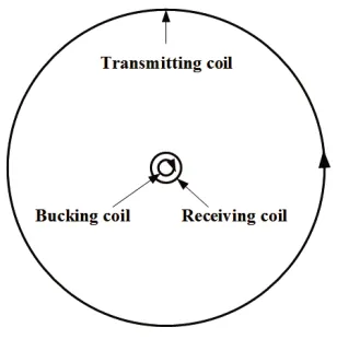
Figure 3. Coils arrangement in our design.
about 1.2 m in diameter [8]. In this design, the bigger the transmitting coil is, the larger and heavier the bucking coil is, and the more difficult is in mounting the bucking coil.
We find that if we put the bucking coil inside the receiving coil and give the bucking coil a proper diameter, the bucking coil can eliminate the primary field in the receiving coil as well. As shown in Fig. 3, from inside to outside of the whole coils system is the bucking coil, receiving coil and transmitting coil. The current direction in the bucking coil needs to be opposite to that in transmitting coil. In the case that the transmitting and receiving coils are the same as that in the VTEM Max system, the diameter of the bucking coil is just 0.43 m when it has 1 turn. It can be seen that the bucking coil is much smaller than that in VTEM Max system. It makes a lighter weight and bigger magnetic moment.
3. CALCULATION OF THE BUCKING COIL DIAMETER
As shown in Fig. 4, the radii of two concentric coils C1 and C2 are r1 and r2, and the turns of the two coils are N1 and N2.
Figure 4. Two concentric coils.
The mutual inductance of the two coils can be calculated by Neumann formula:
M = μ0N1N2 4π
C1
C2
dl1dl2cosθ
R (1)
Obtained by integration, the mutual inductance can be simplified to:
M =μ0N1N2(r1r2)12
2 k−k
K(k)− 2 kE(k)
but also in our design.
The magnetic flux in the receiving coil generated by the transmitting coil can be written as,
ΦT R=MT RIT (6)
where MT R denotes the mutual inductance of the transmitting coil and receiving coil, and IT is the
transmitting current.
In the same way, the magnetic flux caused by the bucking coil in the receiving coil can be expressed as,
ΦBR=MBRIB (7)
whereMBRis the mutual inductance of the bucking coil and receiving coil. IB is the current flowing in
the bucking coil. In the AEM systems, the currents in the bucking coil and transmitting coil are always the same in amplitude and opposite in direction, i.e.,IT =−IB.
To eliminate the primary field in the receiving coil caused by the transmitting coil, we just need to make the superposed magnetic flux in the receiving coil equal to zero. Combined with Eqs. (6) and (7), the relationship of the two mutual inductances, i.e., the mutual inductance of the transmitting and receiving coils, and that of the bucking and the receiving coils, is obtained:
MT R=MBR (8)
So, when the diameters of the transmitting coil and receiving coil are given, and the turns of the transmitting coil is known, the diameter of the bucking coil can be calculated by using Eqs. (2) and (8).
4. COMPARISON OF THE TWO DESIGNS
We illustrate the advantage of our design over the traditional design. Some comparisons have been made in the bellow.
4.1. Diameter of the Bucking Coil versus Transmitting Coil
Consider that the receiving coil is fixed. The diameter of the receiving coil is 1.2 m, and the turns is 100. The ratio of the turns of transmitting coils to bucking coil is 4. The diameters of the two bucking coils in the two designs versus the transmitting coil diameter are shown in Fig. 5. The diameter of the transmitting coil is from 17.5 m to 35 m.
20 25 30 35
Diameter of the transmitting coil(m)
(a) 4 5 6 7 8 9 Diameter (m)
20 25 30 35
Diameter of the transmitting coil(m)
(b) 0.4 0.45 0.5 0.55 0.6 Diameter (m)
Figure 5. The diameter of the bucking coil versus the diameter of the transmitting coil: (a) the diameter of the bucking coil in the traditional design; (b) the diameter of the bucking coil in our design.
4.2. Influence of the Magnetic Moment
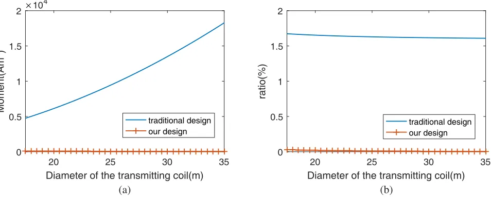
Bucking coil is introduced to eliminate the primary field; however, it produces a side effect that the opposite bucking moment will decrease the total moment of the system. Assume that the current in transmitting coil and bucking coil is 300 A. The bucking moment and ratio of the bucking moment to total moment are calculated, and the results are shown in Fig. 6.
From Fig. 6, we can see that the moment of the bucking coil in the traditional design is much bigger than that in our design. The difference grows larger with increasing diameter of the transmitting coil. In traditional design, the bucking moment is increased from 4.7 k Am2 to 18 k Am2 when the diameter of transmitting coil is from 17.5 m to 35 m. Meanwhile, the bucking moment in our design is decreased from 84 Am2 to 44 Am2. Fig. 6(b) shows the influence of the total magnetic moment in the two designs. The ratio of the bucking moment to total moment remains above 1.5% in traditional design and below 0.03% in our design. The influence of the moment caused by the bucking coil in our design is so small that it can be ignored.
20 25 30 35
Diameter of the transmitting coil(m)
(a) 0 0.5 1 1.5 2 Moment(Am 2 )
×104
traditional design our design
20 25 30 35
Diameter of the transmitting coil(m)
(b) 0 0.5 1 1.5 2 ratio(%) traditional design our design
20 25 30 35
Diameter of the transmitting coil(m)
(a) 0
10 20
Weight(Kg)
traditional design our design
20 25 30 35
Diameter of the transmitting coil(m)
(b) 0
2 4 6
ratio(%)
traditional design our design
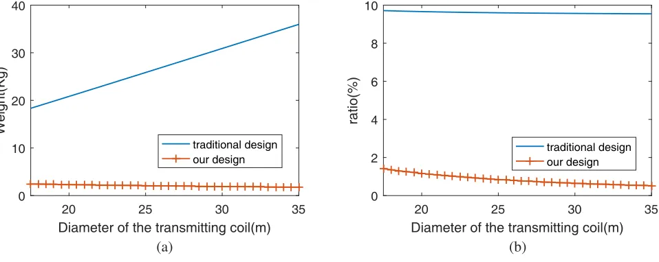
Figure 7. Weight comparison with the two designs: (a) weight of the bucking structure; (b) ratio of the bucking weight to the total weight.
As shown in Fig. 7(a), the weight of the bucking structure in the traditional design increases with the diameter of transmitting coil, and the weight of the bucking structure is doubled when the diameter is doubled. However, in our design, the weight of the bucking structure stay almost the same. It can be inferred from Fig. 7(b) that the ratio of the bucking structure to the total structure in the traditional design remain nearly the same with the increase of the diameter of the transmitting coil. On the other hand, in our design the ratio is decreased from 1.4% to 0.5%.
5. SIMULATED RESULTS
A simulation is carried out by using MAXWELL to measure the receiving coil response with bucking coil in two designs. The receiving coil of the HTEM system is 1.2 m in diameter, with 100 turns. The transmitting coil is 35 m in diameter, with 4 turns. The diameter of the bucking coil is 8.808 m in the traditional design, while ours is 0.433 m, and both have one turn. The transmitting current is 200 A with switch-off time of 1 ms. The result in Fig. 8 show that the coil responses, also called the secondary field, are almost the same in the two designs. The amplitude is little smaller in our design in the switch-off time because the diameter of the wire is not zero in practice, and the primary field is eliminated thoroughly. However, the response in the off-time (after 1 ms) is slight bigger in our design due to the bigger effective magnetic moment.
6. DISCUSSION
0 1 2 3 4 5 6 t(ms) -3 -2 -1 0 1 2 3 Voltage (mV) traditional design our design
Figure 8. Receiving coil response measured with bucking coil.
-1 -0.5 0 0.5 1
offset of the bucking coil size(cm) (a) 0 2 4 6 8 10 12 relative ratio(%)
0 2 4 6 8 10
offset of the bucking coil location(cm) (b) 0 0.5 1 1.5 2 2.5 3 relative ratio(%)
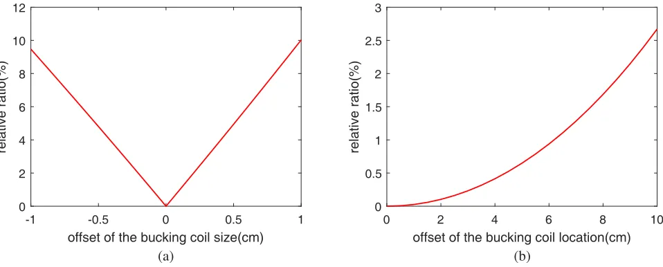
Figure 9. The relative ratio of residual primary field caused by imperfect bucking coil in our design to the primary field caused by the transmitting coil: (a) residual primary field caused by improper bucking coil size; (b) residual primary field caused by improper bucking coil location.
It can be inferred from Fig. 9(a) that the bucking result is very sensitive to the size of bucking coil. The residual primary field will be up to 10% of the sum primary field by the transmitting coil when the bucking size is 1 cm bigger or smaller. If we want to keep the residual primary field under 1%, the precision of 1 mm is required for the manufacturing technique. Fortunately, the bucking coil is small in our design. Its diameter is 0.433 m when the diameter of the transmitting coil is 35 m, which makes it easy to ensure that the diameter of the bucking coil is within 1 mm of the accuracy by advanced technology. From Fig. 9(b), we can see that it needs accurate location when installing the bucking coil. The precision of 6 cm is needed if we want to keep the residual primary field under 1%. So there should be a rigid structure between bucking coil and receiving coil to prevent the relative movement of the two coils.
offset of the bucking coil size(cm) (a)
offset of the bucking coil location(cm) (b)
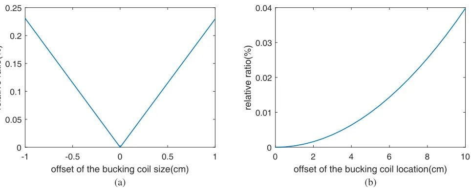
Figure 10. The relative ratio of residual primary field caused by imperfect bucking coil in traditional design to the primary field caused by the transmitting coil: (a) residual primary field caused by improper bucking coil size; (b) residual primary field caused by improper bucking coil location.
7. CONCLUSIONS
In order to decrease the side effect of the bucking coil, which is used to eliminate the primary field in the receiving coil caused by the transmitting coil, a new design is proposed in this paper. The bucking coil is more than 8 times smaller than that in traditional design when the transmitting coil diameter is from 17.5 m to 35 m. Thus, the bucking coil is easier to install, and the integration of HTEM system is easier to achieve. Another advantage of our design is that the bucking coil gets smaller with the increase of the transmitting coil. To reach the perfect result, we need to control the manufactory of the bucking coil in 1 mm and the installation in 6 cm when the residue primary field is under 1%.
ACKNOWLEDGMENT
The authors would like to thank Dr. Liu Lihua and Jutao Li for stimulating discussion during this work.
REFERENCES
1. Yin, C. C., B. Zhang, Y. H. Liu, X. Y. Ren, Y. F. Qi, Y. F. Pei, C. K. Qiu, X. Huang, W. Huang, J. J. Mia, and J. Cai, “Review on airborne em technology and developments,”Chinese J. Geophys.-Ch., Vol. 58, No. 8, 2637–2653, 2015.
2. Schamper, C., E. Auken, and K. Srensen, “Coil response inversion for very early time modelling of helicopter-borne time-domain electromagnetic data and mapping of near-surface geological layers,” Geophysical Prospecting, Vol. 62, No. 3, 658–674, 2014.
3. Legault, J. M., C. Izarra, A. Prikhodko, S. K. Zhao, and E. M. Saadawi, “Helicopter EM (ZTEM-VTEM) survey results over the nuqrah copper-lead-zinc-gold sedex massive sulphide deposit in the western arabian shield, kingdom of saudi arabia,” Exploration Geophysics, Vol. 46, No. 1, 36–48, 2015.
4. Holladay, J. S., W. E. Doll, L. P. Beard, J. L. C. Lee, and D. T. Bell, “Uxo time-constant estimation from helicopter-borne tem data,”Journal of Environmental and Engineering Geophysics, Vol. 11, No. 1, 43–52, 2006.
6. Shudong, C., W. Yujie, and Z. Shuang, “Bucking coil used in airborne transient electromagnetic survey,” 2012 International Conference on Industrial Control and Electronics Engineering, 478– 481, IEEE, 2015.
7. Witherly, K., R. Irvine, and B. Morrison, “The Geotech VTEM time domain helicopter EM system,” Society of Exploration Geophysicists, 1217–1220, 2004.