Dynamic Modelling of Induction Motor Squirrel Cage for Different
Shapes of Rotor Deep Bars with Estimation of the Skin Effect
Zakari Maddi* and Djamal Aouzellag
Abstract—This paper presents a dynamic modelling of a series of induction motors (IM) squirrel cage with different shapes of rotor deep bars taking into account the skin effect. The approach is divided into two parts. The first part consists in modelling the skin effect in a rectangular rotor deep-bar with three methods (conventional analytical method, finite element method and analysis method of circuit). These are compared (estimate of the relative error), and subsequently, generalized to more complex forms (trapezoidal, inverted, direct trapezoidal and double cage), done by using the two last methods which take into account the geometrical non-linearity of the slots. The second part consists in a dynamic modelling with variable parameters that take into account the skin effect, simulated for a series of motors with the same power (with different geometric shapes of rotor bars), to see their influence on the starting characteristics of these IM, and the results are compared and discussed.
1. INTRODUCTION
The modelling of induction machine with fixed parameters is continuously used nowadays. Nevertheless, its operations in the field with variable frequency, particularly for motors with high power, which have sufficiently deep rotor bars, cannot be represented by a constant rotor resistance and leakage reactance. The nonuniform dispersion of the current density, which passes through these bars, induces skin effect phenomenon. The latter is manifested in high frequency and when the height of the slot is of the order of 20 mm at least [1]. It makes the current flow focus on the periphery of conductor, when the frequency is high. Therefore, its section decreases, and its resistance increases, reducing the calling of the current and amplifying the torque at starting. This principle is used in the motors with deep bars, to improve their characteristics and starting performances.
Several research works have been carried out in order to estimate this electromagnetic phenomenon, using various analytical and numerical methods [2–8], which is treated in the case of steady state of IM. This article proposes a non-steady-state analysis of the series IM squirrel cage, with the same power and different forms of rotor bars, taking into account the nonuniform displacement of the currents in those bars (skin effect phenomenon) and their geometrical deformations, in order to observe the behaviour of the latter with respect to the rotor parameters and the transient performances of these motors when they operate such as in direct on-line start. To do this, a rectangular bar has been modelled using three methods for estimating this phenomenon. This is interpreted as two frequency function coefficients depending on the resistance and leakage reactance noted as kr and kx, respectively. The first method is a classical analytical method based on geometric and triangular relations, which offers a good result, verified by many authors as in the case of [7, 10, 11]. The second is a numerical finite element approach, which takes into account the complexity of the geometric shapes of the bars [9]. The last is an analysis method of circuits, which divides the slot in several resistances and leakage reactances in parallel and
Received 5 June 2017, Accepted 24 July 2017, Scheduled 17 August 2017 * Corresponding author: Zakari Maddi ([email protected]).
allows the calculation of the currents travelling through each branch [10]. However, the first method is limited by the geometric complexity of the bars (valid only in the case of simple geometry, i.e., rectangular or circular, etc.). To remedy this problem, it is compared (estimation of the relative error) with the last two methods previously cited (numerical method and circuit analysis), with the aim of validating them, thus to allow a more general approach to the geometric forms of more complex slots.
Finally, a dynamic model of two-phase equations of IM (Park transformation), which takes account of the skin effect is proposed. A simulation of the starting electromechanical characteristics (torque and speed) of the series of motors with different shapes of rotor bars is carried out and compared with a conventional model (without skin effect) in order to see the influence of this phenomenon on the transient characteristics of those motors and approach its performances in real time operation.
2. MODELLING OF A RECTANGULAR DEEP BAR
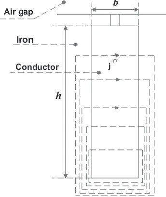
The transition of sinusoidal currents in a conductor material, which has a sufficient height, creates an alternating flux, inducing the skin effect phenomenon, which can be determined mathematically (analytically) by knowing the physical and geometrical properties of the conductor. In order to estimate this phenomenon, a rectangular deep bar as shown in Figure 1 is modelled, and this phenomenon is interpreted as the ratio between the resistance and leakage reactance in the AC and the resistance and leakage reactance in DC, respectively, as expressed by Equations (1) and (2) [7].
kr = rAC
rDC = h
δ ×
sinh
2h δ
+ sin
2h
δ
cosh
2h δ
−cos
2h δ
(1)
kx = LAC
LDC = 3δ
2h×
sinh
2h δ
−sin
2h δ
cosh
2h δ
−cos
2h δ
(2)
where: δ=πμgfρ ,rDC =ρhbl and LDC =μ0l3hb.
krandkx: Coefficients which take into account the increase of resistancerACand decrease of leakage inductance LAC, respectively; δ: Penetration depth which is inversely proportional to the pulsation of
h
b
Iron Air gap
Conductor j
the current in the slot and depends on the material used;ρ: Resistivity of the material;μ: Permeability of the material; f: Frequency of the alternating field; h: Height of the bar; l: Length of the rotor; b: Width of the bar.
The quantityζ =
h
δ is directly proportional to the height and the square root of frequency. On the other hand, this phenomenon occurs whenhandf have significant values. Physical quantities such as the current or magnetic field have an exponential decay in the skin thickness.
This approach is limited to the case of a simple bar section (rectangular, square, etc.). A resolution field calculation, based on the finite element method (FEM), is presented below to approach this analytical method using the FEMM software [12].
3. NUMERICAL MODELLING
At first, a complete structure of the IM is simulated in a 2D magneto-dynamic equation in terms of the potential vector A, under harmonic hypothesis and is solved using the FEMM software packages. This is done over a frequency range (0 to 50 Hz) in order to determine the rotor impedance. The latter is divided on the resistance and leakage reactance in DC (current uniformly distributed), to determine the coefficients shown in Equations (1) and (2).
3.1. Simulation Structure of IM
A structure of medium power IM with rectangular deep bars (15 kW, 2p= 4) is presented and simulated with function of the frequency. The results are shown in Figure 2.
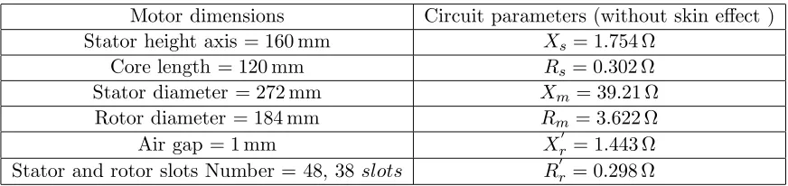
The main dimensions of the simulated motor are presented in Table 1.
Table 1. Parameters and dimensions of the IM studied.
Motor dimensions Circuit parameters (without skin effect ) Stator height axis = 160 mm Xs= 1.754 Ω
Core length = 120 mm Rs= 0.302 Ω
Stator diameter = 272 mm Xm= 39.21 Ω
Rotor diameter = 184 mm Rm = 3.622 Ω
Air gap = 1 mm Xr = 1.443 Ω
Stator and rotor slots Number = 48, 38slots Rr= 0.298 Ω
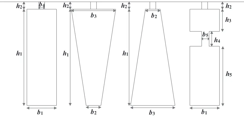
Nevertheless, this method requires considerable time for a simple calculation of the rotor impedance. For this reason, a single bar of different geometric forms is analysed for a similar simulation. Their respective shapes and dimensions are shown in Figure 3, where h1 = 29.5 mm, h2 = 0.7 mm,
h3 = 9.5 mm, h4 = 4 mm, h5 = 20.5 mm, b1 = 5.7 mm, b2 = 4 mm, b3 = 7 mm, b4 = 0.5 mm,
b5 = 1.5 mm. The bar section is equal to 169 mm2.
However, in order to have the same behaviour of the field lines in the bars similar to Figure 2, the following boundary conditions are applied as follows:
• The Neumann conditions (δ δtA = 0) are applied on the left and right sides of the bar in order to have the field lines perpendicular to the faces of the bar (to force the stream to cross the border with 90◦);
• The Dirichlet conditions (A= 0) are applied to the up and down sides, to force the flux parallel to the boundary [13].
3.2. Simulation of a Rectangular Bar
h 2
h 1
b 1
b 3
b4 h2 h2 h2
b2
b5
h3
h5
h4
b 1
b2 b 3
h 1 h 1
Figure 3. Geometries of different forms of slots.
(a) (b) (c)
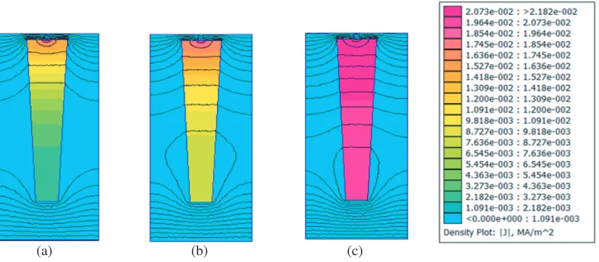
Figure 4. Current densities and field lines in a rectangular bar at different frequencies. (a) 50 Hz. (b) 20 Hz. (c) 5 Hz.
According to Figure 2, the simulation conditions are reproduced, and the field lines are perpendicular to the vertical face. The current density values are more significant in the direction of the air gap when the frequency is high. This method allows a good accurate and quick calculation compared to a complete structure of the IM that takes a considerable time.
From Figure 4, at f = 50 Hz, which means at the motor start-up, the current density does not use the whole section of the conductor, but it is confined to the outer layers close to the surface of the conductor. So there is a focusing of the current lines on the outer surface of the conductor. This occurs when either the frequency (f), the permeability (μ) or the conductivity (σ) is high. At the end of the regime (f = 5 Hz), the current density is distributed uniformly over the whole section of the bar, and the resistance in this case decreases.
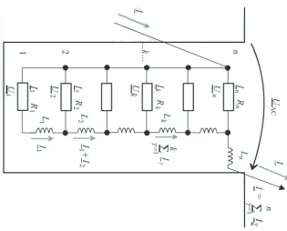
4. MODELLING OF SLOTS BY THE THEORY OF CIRCUITS
arbitrary shapes [10, 14]. This slot is divided into n elementary or fictional sub-conductors that allow to have a simple geometric structure close to a rectangle. This division is reflected by a resistance and leakage reactance in parallel (Figure 5). The latter are traversed by an uniform current (without skin effect). It means that the penetration depth of the magnetic field in the aluminium is lower than the radial dimensions of the sub-conductors [11].
In the steady state, referring to Figure 5, the voltage equation in thekth sub-conductors is expressed
as follows: .
Ek=−jω .
ΔΦk=Rk .
Ik−Rk+1 .
Ik+1 (3)
where ΔΦk: Leakage flux which circulates between the kth and (k+ 1)th sub-conductors.
Figure 5. Rotor slot divided into elementary sub-conductor.
The flux densityBk in sub-conductor kdepends on the current liaison ζ (F.M.M) calculated from the bottom of the slot in sub-conductork.
ζk =
Bk
μ0dl
(4)
Bk = μ0
ζ bk
=μ0
1
bk k
γ=1
iγ (5)
wherebk is the width of the slot to the position of thekth sub-conductor.
ΔΦk=Bklhk=μ0ζk
bklhk
=μ0lhk
bk k
γ=1
iγ (6)
By substituting Eq. (4) into Eq. (6), we get:
.
Ek=−Jωμ0lhk
bk k
γ=1 .
Iγ=Rk .
Ik −Rk+1 .
Ik+1 (7)
Then we obtain:
.
Ik+1= Rk
Rk+1 .
Ik+Jωμ0lhk
Rk+1bk k
γ=1 .
Iγ= Rk
Rk+1 .
Ik +J ωLk
Rk+1 k
γ=1 .
The resistance and inductance of the elementary conductor kare:
Lk = μolhk
bk
(9)
Rk = ρ l
hkbk
(10)
If the value of current .
I1 is not known, we impose an arbitrary value (for example 1A), and the rest of
the currents will be resolved according to the following equations system in Eq. (11). ⎧ ⎪ ⎪ ⎪ ⎪ ⎪ ⎪ ⎪ ⎪ ⎪ ⎪ ⎪ ⎪ ⎪ ⎪ ⎪ ⎪ ⎪ ⎪ ⎨ ⎪ ⎪ ⎪ ⎪ ⎪ ⎪ ⎪ ⎪ ⎪ ⎪ ⎪ ⎪ ⎪ ⎪ ⎪ ⎪ ⎪ ⎪ ⎩ .
I1= 1 .
I2= R1
R2 .
I1 +JωL1
R2 .
I1 .
I3= R2
R3 .
I2 +JωL2
R3
( .
I1 + .
I2)
. . .
.
Ik+1= Rk
Rk+1 .
Ik+J ωLk
Rk+1
( .
I1 + .
I2 +...+ .
Ik) .
. .
In= Rn−1
Rn .
In−1 +JωLn−1
Rn n−1
γ=1 .
Iγ
(11)
In this way, all the currents of sub-conductors are determined. The total current in the bar is:
.
Ib= n
γ=1 .
Iγ (12)
After getting the current from Eq. (11), the rest of calculation will be as follows. The resistance of the barRbe taking into account the skin effect is given by [10]:
Rbe = n
γ=1
Iγ2Rγ
Ib2
(13)
The coefficient which takes into account the increase in resistance of the bar is expressed as follows:
kr= Rbe
rDC
(14)
The coefficientλbe of the slot dispersion conductivity taking into account the skin effect is given by the following expression [15]:
λbe = n γ=1 ⎛ ⎝λγ n
k=γ . Ik 2⎞ ⎠
Ib2
(15)
The coefficient λb2 of the slot dispersion conductivity without skin effect is given by [15]:
λb2 = n γ=1 ⎛ ⎝λγ ⎛
⎝n
k=γ
qk ⎞ ⎠
2⎞ ⎠
qb2
(16)
The coefficient which takes into account the decrease of the conductivity dispersion in slot is given by the formula:
kx= λbe
λb2
(17)
5. SIMULATION RESULT
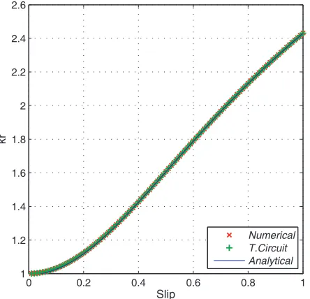
The simulation results obtained by the three methods presented above for a rectangular bar are shown in Figures 6 and 7.
0 0.2 0.4 0.6 0.8 1
1 1.2 1.4 1.6 1.8 2 2.2 2.4 2.6
Slip
kr
Numerical T.Circuit Analytical
Figure 6. Evolution of kr with function of the slip.
0 0.2 0.4 0.6 0.8 1
0.65 0.7 0.75 0.8 0.85 0.9 0.95 1
Slip
kx
Numerical T.Crictuit Analytical
Figure 7. Evolution of kx with function of the slip.
The relative error between the three methods is presented in Figure 8.
0 0.2 0.4 0.6 0.8 1
0 0.1 0.2 0.3 0.4 0.5 0.6 0.7 0.8
Slip
Relative Error %
[kr] Anlalytical/T.Circuit [kr] Anlalytical/Numerical [kx] Anlalytical/Numerical [kx] Anlalytical/T.Circuit
(a) (b) (c)
Figure 9. Finite element simulation of trapezoidal slot. (a) 50 Hz. (b) 20 Hz. (c) 5 Hz.
0 0.2 0.4 0.6 0.8 1
1 1.1 1.2 1.3 1.4 1.5 1.6 1.7 1.8 1.9 2
Slip
kr
Numerical T.Circuit
Figure 10. Evolution ofkrin function of the slip.
0 0.2 0.4 0.6 0.8 1
0.65 0.7 0.75 0.8 0.85 0.9 0.95 1
Slip
kx
Numerical T.Circuit
Figure 11. Evolution of kx in function of the slip.
According to Figures 6 and 7, an exponential increase ofkr coefficient is noticed, which results in an increase in resistance of a value ofs= 2.41 to 1. Conversely forkx coefficient decreases and reduces the leakage reactance of a factor equal to 0.6 at the start, the calling of the current is reduced in this case, and the IM power factor is optimized.
Figure 8 shows the relative error of the three methods (using the analytical method as a reference), where [An]: analytical solution; [T.C]: solution by theory of circuit; [Num]: numerical solution.
According to this figure, the results are homogeneous (maximum relative error equal to 0.76%), which justifies the approach followed. In another way, this insignificant relative error value allows deepening our approach for more complex geometric forms, using the numerical method and theory of circuits.
5.1. Direct Trapezoidal Slot
This structure is generally found in IM with small power which does not require a high starting torque. The bar is simulated as a function of frequency, and the results are shown in Figure 9.
The curves of the two coefficients kr and kx for a trapezoidal slot are as in Figures 10 and 11. The curves of kr and kx are similar to those found previously (rectangular bar), with little lower values ofkr and higher value of kx at start-up, which is explained by the decrease of the resistance and rising of the reactance, due to the increase of the section occupied by the current.
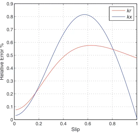
Figure 12 presents the relative error for the two coefficients, and in this case it does not exceed 0.82%.
5.2. Trapezoidal Inverted Slot
This structure is used in the case of external rotor motor with a great power (to avoid magnetic saturation in the end-bars). The simulation results by field calculations are shown in Figure 13.
0 0.2 0.4 0.6 0.8 1
0 0.1 0.2 0.3 0.4 0.5 0.6 0.7 0.8 0.9
Slip
Relative Error %
kr kx
Figure 12. Relative error in function of the slip.
(a) (b) (c)
The comparison of kr and kx coefficients for trapezoidal inverted slot gives the results as in Figures 14 and 15.
0 0.2 0.4 0.6 0.8 1
1,4 1,8 2,2 2,6 3
Slip
kr
Numerical T.Circuit
Figure 14. Evolution ofkrin function of the slip.
0 0.2 0.4 0.6 0.8 1
0.65 0.7 0.75 0.8 0.85 0.9 0.95 1
Slip
kx
Numerical T.Circuit
Figure 15. Evolution of kx in function of the slip.
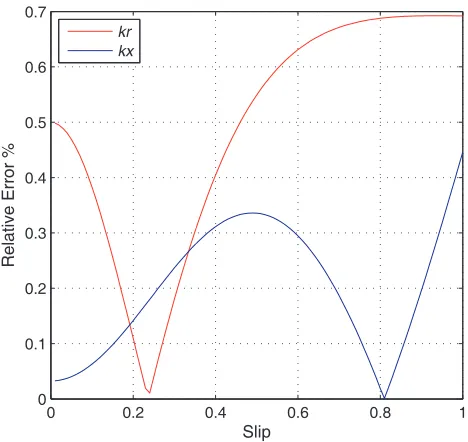
We notice an increase in the value of kr and a slight variation of kx coefficient in Figures 14 and 15 compared to the values found previously at starting, which is explained by the reduction of the bar section in direction of air gap. The relative error in this case is shown in Figure 16.
0 0.2 0.4 0.6 0.8 1
0 0.1 0.2 0.3 0.4 0.5 0.6 0.7
Slip
Relative Error %
kr kx
Figure 16. Relative error in function of the slip.
5.3. Double Cage Slot
This form is used in the case of high power and large diameter machines and those starting on load. The simulation results are as in Figure 17.
(a) (b) (c)
Figure 17. Finite element simulation of double cage slot. (a) 50 Hz. (b) 20 Hz. (c) 5 Hz.
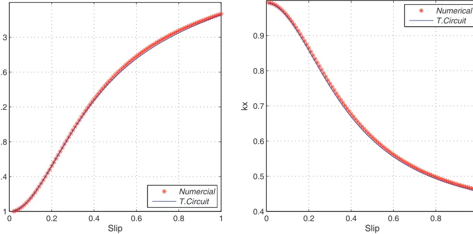
The curves of developments ofkr andkx coefficients for double cage slot by two methods are as in Figures 18, 19, and 20.
From Figures 18 and 19, this case has a slight deformation characteristics of kr and kx, which is explained by the absence of the magnetic flux in the inner cage, as shown in Figure 17 (the magnetic flux is close in the intermediate part of the two cages), and the height of this bar is slightly higher than
0 0.2 0.4 0.6 0.8 1
1 1.4 1.8 2.2 2.6 3
Slip
kr
Numercial T.Circuit
Figure 18. Evolution ofkrin function of the slip.
0 0.2 0.4 0.6 0.8 1
0.4 0.5 0.6 0.7 0.8 0.9
Slip
kx
Numerical T.Circuit
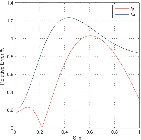
0 0.2 0.4 0.6 0.8 1 0
0.2 0.4 0.6 0.8 1 1.2 1.4
Slip
Relative Error %
kr kx
Figure 20. Relative error in function of the slip.
the previous cases. Over the outer cage there is a small section, that is whykr is higher and kx lower. The maximum relative error for this form is 1.2% which is greater than that calculated for the other forms.
The results obtained for the different forms studied are satisfactory from a precision viewpoint. However, those methods only take into account the behaviour of the conductors inside the magnetic circuit. Leaks due to the isthmus of slots are not included, and the resistance and leakage reactance, for the end-bars, and the effect of magnetic saturation are neglected [11, 13].
In order to take into account this variation of rotor parameters, a corrected dynamic modelling is presented below.
6. DYNAMIC MODELLING OF IM
To complement this work, i.e., to see the influence of the skin effect and geometric deformation of the bars on the transient performances of the IM, a dynamic modelling in thedqreference (Park transformation) with variable parameters is presented below. The corrected systems of equations are given by Eqs. (18) to (20):
⎧ ⎪ ⎪ ⎪ ⎪ ⎪ ⎪ ⎪ ⎪ ⎪ ⎨ ⎪ ⎪ ⎪ ⎪ ⎪ ⎪ ⎪ ⎪ ⎪ ⎩
Vds =Rsids+Lsdids
dt +M didr
dt −ωs(Lsiqs+M iqr) Vqs =Rsiqs+Lsdiqs
dt +M diqr
dt +ωs(Lsids+M idr) Vdr = (krRe+Rf)idr+ (kxle+lf)
didr
dt +M dids
dt −(ωs−ωr)((kxl
e+lf)iqr+M iqs)
Vqr = (krRe +Rf)iqr+ (kxle+lf)
diqr
dt +M diqs
dt + (ωs−ωr)((kxl
e+lf)idr+M ids)
(18)
The stator and rotor flux are connected to current by the following equations: ⎧
⎪ ⎪ ⎪ ⎨ ⎪ ⎪ ⎪ ⎩
φds=Lsids+M idr
φqs=Lsiqs+M iqr
φdr = ((kxle+lf) +M)idr+M ids
φqr= ((kxle+lf) +M)iqr+M iqs
where Rs and Ls: Stator resistance and leakage inductance; M: Mutual inductance; Re and le: Resistance and dispersion of leakage inductance of the bar portion to a uniform repairing current returned to the stator, respectively; Rf and lf: Resistance and leakage inductance of the frontal part of the bar returned to the stator, respectively.
The expression of the electromagnetic torque is given as a function of the stator flux and stator currents by the following expression:
Te=p(φdsiqs−φqsids) (20)
6.1. Starting Performance of the IM
A series of simulation blocks in MATLAB/Simulink is developed, taking into account the coefficients and for forms of slots previously presented, in order to see their influence on the characteristics of the IM. The results are illustrated in Figures 21 and 22.
0 0.2 0.4 0.6 0.8 1
200 100 0 100 200 300 400 500
Slip
Te [N.m]
Double cage
Trapezoidal inverted
Rectangular
Trapezoidal
Without skin effect
Figure 21. Electromagnetic torque versus slip.
0 2 4 6 8 10 12
0 20 40 60 80 100 120 140 160
Time [s]
Speed [rad/s]
Double cage Trapezoidal inverted Rectangular Trapezoidal Without skin effect
Figure 22. Speed evolution versus time.
6.2. Interpretation Results
According to Figures 21 and 22, in the case without skin effect, the starting torque is very low. The motor takes a considerable time to start. Contrary to the other cases (with skin effect), the dynamism of the motor is improved, which depends on the shape of the rotor bar. Those that tend to reduce the section of the bar in the direction of the air gap (inverted trapezoidal and double cage) have better value of the torque at start-up and a shorter time, because the current tends to circulate on the upper part of the conductor. On the other hand, for the case of the trapezoidal slot, the cross-section is large, where the current density is high, and skin effect in this case is reduced.
The advantage of the double cage motor is to operate with lower speed because the unstable region is nonexistent (the torque is still higher than the resistive torque).
7. CONCLUSION
This approach improves accuracy in the analysis of the transient performance of induction machines, while approaching its characteristics in real time operation. The latter offers the possibility of estimating the nonlinear distribution of the currents, circulating in the rotor bars under the various conditions of its variable frequency operation, for an arbitrary geometry of rotor bars.
REFERENCES
1. Kostenko, M. and L. Piotrovski, Machines ´electriques, Tome II, Editions mire, Moscou, Russia, 1979.
2. Smith, A. C., R. C. Healey, and S. Williamson, “A transient induction motor model including saturation and deep bar effect,” IEEE Transactions on Energy Conversion, Vol. 11, No. 01, 8–15, 1996.
3. Choudhury, Md. S. H., M. A. Uddin, Md. N. Hasan, and M. Shafiul, “Impact of skin effect for the design of a squirrel cage induction motor on its starting performances,” International Journal of Engineering Science and Technology, Vol. 04, No. 01, Engg Journals Publications, 2012.
4. Boglietti, A., A. Cavagnino, and M. Lazzari, “Computational algorithms for induction motor equivalent circuit parameter determination — Part II: Skin effect and magnetizing characteristics,” IEEE Transactions on Industrial Electronics, Vol. 58, No. 09, 3734–3740, 2011.
5. Saied, B. M. and A. J. Ali, “Determination of deep bar cage rotor induction machine parameters based on finite element approach,” 2012 First National Conference for Engineering Sciences (FNCES), 1–6, IEEE, 2012.
6. Jelassi, S., R. Romary, and J. F. Brudny, “Slot design for dynamic iron loss reduction in induction machines,”Progress In Electromagnetics Research B, Vol. 52, 79–97, 2013.
7. Liwschitz-Garik, M., “Skin-effect bars of squirrel-cage rotors,” Electrical Engineering, Vol. 70, No. 06, 504–504, 1954.
8. Babb, A. S. and J. Williams, “Circuit analysis method to determination of A-C of machines conductor,”AIEE Trans., Vol. 70, No. 10, 661–666, 1951.
9. Pyrhnen, J., T. Jokinen, and V. Hrabovcov, Design of Rotating Electrical Machines, Wiley, 2008. 10. Boldea, I. and S. A. Nasar,The Induction Machine Handbook, Finite Element Method Magnetics,
User’s Manual, CRC Press, 2010.
11. Pusca, R., R. Romary, V. Fireteanu, and A. Ceban, “Finite element analysis and experimental study of the near-magnetic field for detection of rotor faults in induction motors,” Progress In Electromagnetics Research B, Vol. 50, 37–59, 2013.
12. Meeker, D. C.,Finite Element Method Magnetics, User’s Manual, 2015.
13. Maddi, Z. D. Aouzellag, and T. Laddi, “Influence of the skin effect and the form of slot on the starting characteristics of induction motor squirrel cage,” International Conference in Recent Advances in Mechanics, Mechatronics and Civil, Chemical and Industrial Engineering, 125–129, 2015.
14. Benecke, M., R. Doebbelin, G. Griepentrog, and A. Lindemann, “Skin effect in squirrel cage rotor bars and its consideration in simulation of non-steady-state operation of induction machines,” PIERS Online, Vol. 7, No. 5, 421–425, 2011.