University of Windsor
University of Windsor
Scholarship at UWindsor
Scholarship at UWindsor
Electronic Theses and Dissertations
Theses, Dissertations, and Major Papers
2016
A Run-Time Approach of Combining Ontologies to Enhance
A Run-Time Approach of Combining Ontologies to Enhance
Interactive Requirements Elicitation for Software Customization
Interactive Requirements Elicitation for Software Customization
Shubhrendu Tripathi
University of Windsor
Follow this and additional works at: https://scholar.uwindsor.ca/etd
Recommended Citation
Recommended Citation
Tripathi, Shubhrendu, "A Run-Time Approach of Combining Ontologies to Enhance Interactive
Requirements Elicitation for Software Customization" (2016). Electronic Theses and Dissertations. 5778.
https://scholar.uwindsor.ca/etd/5778
A Run-Time Approach of Combining Ontologies to Enhance
Interactive Requirements Elicitation for Software Customization
by
Shubhrendu Tripathi
A Thesis
Submitted to the Faculty of Graduate Studies
through Computer Science
in Partial Fulfillment of the Requirements for
the Degree of Master of Science at the
University of Windsor
Windsor, Ontario, Canada
2016
c
A Run-Time Approach of Combining Ontologies to Enhance
Interactive Requirements Elicitation for Software Customization
by
Shubhrendu Tripathi
APPROVED BY:
Dr. A. Azab
Dept. of Industrial & Manufacturing Systems Engineering
Dr. S. Goodwin
School of Computer Science
Dr. X. Yuan, Advisor
School of Computer Science
Declaration of Co-Authorship /
Previous Publication
I. Co-Authorship Declaration
I hereby declare that this thesis incorporates material that is result of joint research of
the author and his supervisor Prof. Xiaobu Yuan. This joint research has been published
/ submitted to various conferences that are listed below.
I am aware of the University of Windsor Senate Policy on Authorship and I certify that
I have properly acknowledged the contribution of other researchers to my thesis, and
have obtained written permission from Prof. Xiaobu Yuan to include those materials in
my thesis.
I certify that, with the above qualification, this thesis, and the research to which it
II. Declaration of Previous Publication
This thesis includes two original papers that have been previously published /
sub-mitted for publication in peer reviewed conferences, as follows:
Thesis Chapter Publication title / Full citation Publication
status
Chapter 3,
Chapter 4,
Chapter 5
Yuan X. and Tripathi S.,
"Combining ontologies for requirements
elicitation," inModel-Driven Requirements
Engineering Workshop (MoDRE), 2015 IEEE International.
IEEE, 2015, pp. 1-5.
Conference Proceeding (Published)
Chapter 3,
Chapter 4,
Chapter 5
Yuan X. and Tripathi S.,
"An approach of dynamically combining
ontologies for interactive
requirements elicitation," in
Software Engineering and Service Science (ICSESS), 2016 7th IEEE International Conference on.IEEE, 2016
Conference Proceeding (In press)
I certify that I have obtained written permissions from the copyright owners to
in-clude the above published materials in my thesis. I certify that the above material
describes work completed during my registration as graduate student at the University
of Windsor.
I declare that, to the best of my knowledge, my thesis does not infringe upon
any-one’s copyright nor violate any proprietary rights and that any ideas, techniques,
quo-tations, or any other material from the work of other people included in my thesis,
published or otherwise, are fully acknowledged in accordance with the standard
refer-encing practices. Furthermore, to the extent that I have included copyrighted material
that surpasses the bounds of fair dealing within the meaning of the Canada Copyright
copyrighted material to be used in this thesis without additional written permission. 1
2.
I declare that this is a true copy of my thesis, including any final revisions, as
ap-proved by my thesis committee and the Graduate Studies office, and that this thesis
has not been submitted for a higher degree to any other University or Institution.
Abstract
This thesis highlights the recent developments in Requirements Engineering for
Soft-ware Product Line Engineering, with a focus on the use of ontology in interactive
Re-quirements Elicitation and the existing techniques of ontology operations. Recent
re-search done in Requirements Elicitation has been towards using ontologies as a
mod-eling basis for gathering requirements. A new algorithm has been developed to
al-low ontologies to be combined at run-time when gathering the requirements of
soft-ware clients. By harnessing knowledge in other ontologies, a more refined set of
re-quirements can be generated. A scenario illustrating the use of ontology
combina-tion towards acquiring requirements for mobile platforms is also provided. The
pro-posed method further enhances the capability of interactive software customization,
thus helping to make Software Product Line Engineering a new practice in software
Dedication
This thesis is dedicated to my dear mother, sister, and late father for their endless
Acknowledgements
I would like to sincerely thank and express my deep sense of gratitude for my
super-visor, Dr. Yuan. He has been very kind and patient throughout this endeavour. Without
his clear and effective guidance, this work would not have been possible. I have been
very fortunate to have a supervisor with a great intellect and vast knowledge, who cared
so much about my work, and who responded to my questions and queries so promptly.
He was consistently supportive and constantly encouraged me to improve and refine
my work. He was always available to discuss any issues, big or small, I had during my
research.
I also want to thank Dr. Goodwin and Dr. Azab. Their comments and suggestions
Table of Contents
Declaration of Co-Authorship / Previous Publication iii
Abstract vi
Dedication vii
Acknowledgements viii
List of Tables xii
List of Figures xiii
List of Acronyms xv
List of Listings xvi
1 Introduction 1
2 Related Work 3
2.1 Overview . . . 3
2.2 Software Customization . . . 3
2.2.1 Overview . . . 3
2.2.2 Software Product Line Engineering . . . 3
2.2.3 Service Oriented Architecture . . . 5
2.2.4 Integrating SPL and SOA . . . 6
2.3 Requirements Elicitation . . . 7
TABLE OF CONTENTS
2.3.2 Requirements Elicitation . . . 7
2.3.3 Ontologies in RE . . . 9
2.4 Interactive Requirements Elicitation . . . 11
2.5 Ontology and Operations . . . 14
2.5.1 Overview . . . 14
2.5.2 What is an Ontology? . . . 14
2.5.3 Operations on Ontologies . . . 16
2.5.3.1 Matching . . . 16
2.5.3.2 Alignment . . . 18
2.5.3.3 Mapping . . . 19
2.5.3.4 Integration . . . 20
2.5.3.5 Merging . . . 21
3 A New Method of Ontology Combination 25 3.1 Overview . . . 25
3.2 Problem Statement . . . 25
3.3 Ontology Combination . . . 26
3.4 Example . . . 27
3.5 Proposed Methodology . . . 31
3.5.1 Definitions . . . 31
3.5.2 Step 1: Generate Correspondences . . . 32
3.5.3 Step 2: Generate Relationships . . . 32
3.5.4 Step 3: Check consistency of combined ontology,
O
c . . . 323.5.5 Step 4: Validation of
O
c. . . 323.6 Design of Algorithms . . . 35
3.6.1 Overview . . . 35
3.6.2 SelectLink algorithm . . . 36
3.6.3 GetCorrespondences algorithm . . . 37
3.6.4 GetRelationship algorithm . . . 40
TABLE OF CONTENTS
3.6.6 GetHighestCM algorithm . . . 44
3.6.7 Time Complexity . . . 45
4 Experiments 47 4.1 Overview . . . 47
4.2 Software . . . 47
4.3 Interface . . . 48
4.4 Experiments . . . 51
4.4.1 Scenario I - Single Ontology . . . 51
4.4.2 Scenario II - Multiple Ontologies . . . 51
4.4.3 Scenario III - Ontology of Mobile SOA Functions . . . 60
4.5 Case Study . . . 63
4.6 Contributions . . . 76
4.6.1 Overview . . . 76
4.6.2 Enhanced Interactive Requirements Elicitation . . . 76
4.6.3 Extending Customization to Mobile Applications . . . 77
5 Conclusion and Future Directions 78 5.1 Overview . . . 78
5.1.1 Conclusion . . . 78
5.1.2 Future Directions . . . 79
Bibliography 80
List of Tables
2.1 Summary of Ontologies in RE . . . 10
2.2 Comparison of Ontology Operations . . . 24
3.1 WordNet and Relationships . . . 42
List of Figures
2.1 Software Product Line Engineering [59] . . . 4
2.2 Service Oriented Architecture [22] . . . 5
2.3 Requirements Engineering processes [68] . . . 8
2.4 Ontology-based Requirement Model [73] . . . 11
2.5 Pseudo code for requirement evaluation process [73] . . . 12
2.6 Interactive Requirements Elicitation system [73] . . . 13
2.7 Ontology as a Semantic Network [27] . . . 14
2.8 Ontology as a UML model [27] . . . 15
2.9 Ontology represented in OWL (excerpt) [27] . . . 15
2.10 Ontology Matching [42] . . . 17
2.11 Partial view of an Ontology Alignment [25] . . . 18
2.12 Ontology Mapping . . . 19
2.13 Ontology Integration [50] . . . 20
2.14 Ontology Merging [39] . . . 22
3.1 Pizzaontology [10] . . . 28
3.2 Foodontology [4] . . . 29
3.3 Excerpt of the Combined Ontology . . . 30
3.4 Methodology . . . 34
4.1 Existing interface of Interactive Requirements Elicitation system . . . 48
4.2 Ontology Combination Viewer (OC Viewer) . . . 49
LIST OF FIGURES
4.4 State of Interactive Requirements Elicitation system after selecting some
requirements . . . 50
4.5 BookStoreontology,OSPLinKRE . . . 52
4.6 Searchontology,OiinKRE. . . 53
4.7 OrderSummaryontology,Oj inKRE . . . 53
4.8 ManagePaymentInfoontology,OkinKRE . . . 54
4.9 Excerpt of Combined Ontology -OSPLandOi . . . 55
4.10 OC Viewer output afterOSPLandOicombination . . . 55
4.11 Excerpt of Combined Ontology -OSPLandOj . . . 56
4.12 OC Viewer output afterOSPLandOjcombination . . . 56
4.13 Excerpt of Combined Ontology -OSPLandOk . . . 57
4.14 OC Viewer output afterOSPLandOk combination . . . 57
4.15 Complete Combined Ontology after three iterations . . . 58
4.16 PlatformMobileontology,OMobile inKRE . . . 61
4.17 Excerpt of Combined Ontology -OSPLandOMobile . . . 62
4.18 OC Viewer output afterOSPLandOMobile combination . . . 62
List of Acronyms
DL Description Logic
JWNL Java WordNet Library
OWL Web Ontology Language
RE Requirements Elicitation
SOA Service Oriented Architecture
SPL Software Product Line
List of Listings
4.1 Dialogue Utterances (Part 1) . . . 65
4.2 Dialogue Utterances (Part 2) . . . 65
4.3 Dialogue Utterances (Part 3) . . . 66
4.4 Dialogue Utterances (Part 4) . . . 66
4.5 Dialogue Utterances (Part 5) . . . 67
4.6 Dialogue Utterances (Part 6) . . . 67
4.7 Dialogue Utterances (Part 7) . . . 68
4.8 Dialogue Utterances (Part 8) . . . 68
4.9 Dialogue Utterances (Part 9) . . . 69
4.10 Dialogue Utterances (Part 10) . . . 69
4.11 Dialogue Utterances (Part 11) . . . 70
4.12 Picked Requirements . . . 71
4.13 Abandoned Requirements . . . 71
4.14 Entire OC Viewer output . . . 72
Chapter 1
Introduction
Software Product Line Engineering (SPLE) is an active area in Software Engineering.
It holds the promise of making software customization as successful as the
assembly-line process in the automotive industry. By reducing bloat of unwanted code in software
systems, customization increases efficiency. In the near future of mobile, wearable and
embedded devices [58], the size of a software program takes on an important
dimen-sion. By utilizing customization, software modules can potentially be assembled and
re-assembled quickly to target different platforms in a cost-effective manner.
Consider-able progress [51] has been made in recent years for realizing this paradigm of software
development.
One of the main subdisciplines of Software Engineering, including SPLE, is
Require-ments Engineering. RequireRequire-ments Elicitation (RE) forms an important part of the
Re-quirements Engineering process. A lot of effort [28] [60] has been put in this area of
research. From the early 1990s to the present, many techniques have been identified
to reduce errors and make the elicitation process work more efficiently. Ontologies have
been used to try and ensure that RE is accomplished in a well-defined manner which
in turn, ensures a robust implementation of a software system. Considerable progress
has been mode towards an interactive mode of RE for software customization [74].
They provide an excellent basis for representing concepts and the relationships
be-tween them. Due to this, they are being increasingly used across a variety of domains
[45] [40].
The existing approach to interactive RE relies on using single ontologies to guide
the interaction [73]. It would be more beneficial to harness knowledge available across
multiple domains to dramatically improve the scope of interaction. Various operations
on ontologies, such as merging, are design time operations and are thus not useful
for an interactive system. Recently [73] with dialogue-based RE, an interactive way of
gathering requirements has been made possible. This thesis proposes a novel method
of Ontology Combinations. It is an approach to obtain knowledge in different ontologies
when requirements elicitation is actually performed. The existing interactive approach
uses a single ontology to drive the RE process of gathering requirements for building
a customized Software Product Line (SPL) application. By bringing together different
ontologies at run-time, this methodology promises to strengthen the interactive RE
process and enhance it considerably. By combining multiple ontologies dynamically at
run-time, a more detailed set of requirements can be obtained. This work defines the
methodology for performing ontology combinations and presents a combine algorithm
along with scenarios illustrating the approach. The contributions of this thesis are:
• An enhanced interactive RE process in which significantly more requirements are
acquired from multiple ontologies through ontology combinations.
• Addition of mobile platform-dependent features to a customized SPL application
by the use of ontology combinations.
Related work in the field of Software Customization, RE, Interactive RE and
Ontolo-gies is surveyed in Chapter 2. The thesis problem statement, along with the proposed
method of Ontology Combination as the solution, is covered in Chapter 3. Chapter 4
covers the details of the implementation and goes over the experiments conducted
with the proposed methodology. It also lists the contributions of this thesis. Chapter 5
Chapter 2
Related Work
2.1
Overview
This chapter surveys the various topics pertinent to the thesis and a literature review
of related work.
2.2
Software Customization
2.2.1
Overview
This section presents an overview of the research area of Software Customization.
It highlights the area of inquiry in the context of background literature.
2.2.2
Software Product Line Engineering
Software Product Line Engineering (SPLE) is defined as a paradigm to develop
soft-ware applications (softsoft-ware-intensive systems and softsoft-ware products) using platforms
and mass customizations [59]. It is divided into two areas: Domain Engineering and
Ap-plication Engineering. Figure 2.1 summarizes the different processes involved in these
2.2 Software Customization
Figure 2.1: Software Product Line Engineering [59]
Both, Domain and Application Engineering, gather requirements for which some
as-pects of Requirements Engineering are needed. Domain Engineering is the process
of SPLE in which the commonality and the variability of a SPL are defined and realised
[59]. It is comprised of five sub-processes: Product Management, Domain Requirements
Engineering, Domain Design, Domain Realisation, and Domain Testing. The Domain
Re-quirements Engineering sub-process covers "all activities for eliciting and documenting
the common and variable requirements of the product line" [59] whereas the Domain
Design sub-process covers activities for defining the reference architecture [59].
Application Engineering is the process of SPLE in which applications of the SPL are
built by reusing domain artefacts and exploiting the product line variability [59]. In
con-trast to Domain Engineering, one of the main goals of Application Engineering is to make
use of the commonality and variability of a SPL to develop a customized product line
ap-plication [59]. Apap-plication Engineering is comprised of four sub-processes: Apap-plication
2.2 Software Customization
Testing. The Application Requirements Engineering sub-process contains activities that
are needed for developing the application requirements specification [59].
Considerable research has been done in the field of SPLE in the past few years [51].
Integrating SPLE and Software Oriented Architecture (SOA) paradigms has also been an
important focal point for researchers, more of which will be covered in a later section.
Various open research challenges can be found for topics encompassing SPLE [51].
Soft-ware factory automation has been proposed [15], analogous to manufacturing factory
automation, for managing reusable assets across distinct SPLs. This model is based on
an architecture-driven meta-model which is customized to create applications directly.
A systematic overview of research literature for product derivation in SPLE has also
been done [60], where requirements are identified and validated for this purpose.
2.2.3
Service Oriented Architecture
Service Oriented Architecture (SOA) is a software model in which automation logic is
decomposed into smaller, distinct units of logic [22]. These units are collectively used
to create a larger piece of business automation logic. Figure 2.2 provides an overview
of this model.
Figure 2.2: Service Oriented Architecture [22]
Services can assume different roles when involved in different scenarios [22]. The
three main roles are, as shown in Figure 2.2, Service Broker, Service Consumer, and
2.2 Software Customization
through which it can be invoked by requestors of the service [22]. A Service Consumer
is the sender of a service message requesting a specific service [22]. A Service Broker
acts as a registry of services, and stores information about what services are available
and who may use them. Universal Description, Discovery and Integration (UDDI) is an
example of a Service Broker.
The core concept in SOA is that these units can be distributed. They don’t need to
reside on the same machine but can be spread across an intranet or even the Internet.
2.2.4
Integrating SPL and SOA
SPL and SOA integration is an active area of research. The various studies done in
this combined field over the last decade have been surveyed [52]. The studies have
been classified according to research focus, types of research and contribution, along
with the various fields of ongoing research.
The concepts of SPL, SOA and component frameworks have been compared [32],
concluding with the assertion that while there are differences between them, these
concepts are in fact complementary to one another. An approach of a service-oriented
architecture in which product lines are regarded as services which are then used to
combine together into another, distinct product line has been presented [67]. A web
product line to showcase this approach has also been provided there. An approach for
reusing and combining services into service oriented product line applications has also
been proposed [43]. Various issues such as identification of services are resolved by
using feature-oriented product line engineering. Another method has been proposed
[37] in which services and their level of granularity are identified by using ontologies
in product lines. A way of grouping features and evaluating services, along with a case
study, has also been provided there.
Developing SOA applications as SPLs has been attempted [49]. A combination of
these two concepts is shown to provide advantages such as improved reuse and
pro-duction of customized applications for specific clients. The issue of service identification
de-2.3 Requirements Elicitation
fined which bridges Feature Models (FMs) in SPLs and Business Process Models (BPMs)
in SOAs by using a BPM workflow model to identify services.
A model using SOA architecture derived from current software artefacts has been
defined [57]. There the focus has been on the reuse of these artefacts as SOA
compo-nents and the derivation process that assembles products out of services automatically.
This proposed approach has been implemented in the form of the Software Product Line
Integration Tool (SPLIT) [56], which has been used to develop modular services obtained
automatically from existing software artefacts. Then out of these services, products are
assembled using a variability-driven derivation process.
2.3
Requirements Elicitation
2.3.1
Overview
This section goes over the relevant research work done in the field of Requirements
Elicitation (RE). It also covers the use of Ontologies in RE.
2.3.2
Requirements Elicitation
Requirements Engineering is comprised of activites related to the development and
agreement of the final set of Requirements Specifications [68]. The various processes
in Requirements Engineering are outlined in Figure 2.3. The main processes used for
a majority of projects are: Requirements Elicitation, Requirements Analysis and
Re-quirements Specification. Other processes, such as ReRe-quirements Prototyping, are also
done for projects where it is feasible to do so. Requirements Elicitation (RE) is defined as
the process of discovering the requirements for a system by communicating with
cus-tomers, system users, and others who have a stake in the development of the system
[63]. It requires specific knowledge of the problem along with application domain and
organizational knowledge. RE plays an important part in Requirements Engineering.
2.3 Requirements Elicitation
Figure 2.3: Requirements Engineering processes [68]
[47]. However, this mode of collecting requirements is ambiguous and a primary source
of errors which leads to flawed and incomplete Requirements Specifications.
Recogniz-ing this, attempts have been made to use computer-assisted tools to gather
require-ments [46]. Extending this paradigm, a human-machine dialogue interface using
natu-ral language promises to reduce errors in the RE process.
In an early work [28], various approaches to obtain requirements were presented
using insight gained from social science paradigms. A prototype automated SPL
engi-neering environment has been presented which utilizes a product line repository [29].
Multiple-view models of SPLs were then used with a Knowledge Based RE Tool to derive
a software product. An approach of interactive RE to build customized software based
on a SPL has been presented recently [74]. An ontology model comprising of
knowl-edge of common and variable assets has been developed, which is then used to obtain
abstract requirements models for specific domains. A case study of an online book
shopping system has also been incorporated into that study to illustrate the approach
2.3 Requirements Elicitation
2.3.3
Ontologies in RE
Ontologies have been defined as "a formal, explicit specification of a shared
con-ceptualization" [65]. They began to be used in Requirements Engineering in the early
1980s [20]. They were used in a variety of domains such as network management [45]
and aerospace [40] [24].
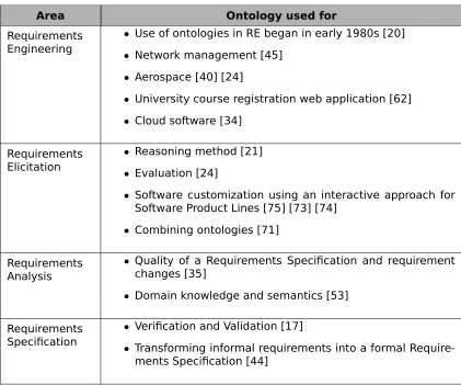
Ontologies have been used for Requirements Analysis [35]. There, the
incomplete-ness and inconsistency in a Requirements Specification was determined by using
on-tologies. The quality of a specification was measured along with predictions made about
requirement changes.
Ontology-based reasoning method for RE has also been introduced [21]. Here,
re-quirements were mapped to functions in domain ontology. Then reasoning was applied
to check for errors and other potential requirements. Ontology-driven guidance has
been used for RE [24]. Evaluation was done based on a domain ontology and a set of
requirements. Further progress has been made in manipulating ontologies by
combin-ing them. Combinations make an effective use of knowledge encapsulated in different
ontologies [71]. A methodology has been established to perform combinations for RE
[71]. Ontology-based RE for software customization, in the context of SPLs, has been
performed using an interactive approach [75] [74].
Ontologies have been developed for various Requirements Engineering processes
using a university course registration web application system as a case study [62].
There, a model called OntoPersonalURM, which uses a multi-step iterative ontology
de-velopment process, was created for Requirements Engineers. Ontology-based relation
mining has been used for Cloud software requirements [34]. Ontologies have also been
used for Requirements Specification verification and validation [17]. Similarly, an
ontol-ogy of requirements has been used in transforming informal requirements into a formal
specification [44].
2.3 Requirements Elicitation
Area Ontology used for
Requirements Engineering
• Use of ontologies in RE began in early 1980s [20]
• Network management [45]
• Aerospace [40] [24]
• University course registration web application [62]
• Cloud software [34]
Requirements Elicitation
• Reasoning method [21]
• Evaluation [24]
• Software customization using an interactive approach for
Software Product Lines [75] [73] [74]
• Combining ontologies [71]
Requirements Analysis
• Quality of a Requirements Specification and requirement
changes [35]
• Domain knowledge and semantics [53]
Requirements Specification
• Verification and Validation [17]
• Transforming informal requirements into a formal
Require-ments Specification [44]
2.4 Interactive Requirements Elicitation
2.4
Interactive Requirements Elicitation
Recently, significant progress has been made towards interactive RE using
ontolo-gies. An interactive machine-guided elicitation of requirements has been developed for
the customization of a SPL for SOA based software [74]. An ontology-based
require-ments model has been developed [73], as shown in Figure 2.4. Three main concepts
have been identified in the model -Requirement,FunctionandQuality. Other concepts
have been included as extensions -Softgoal,RankandOtherInfo. Seven relationships
have been developed -Generalize,Decompose,Rely,Contradict,Associate,HasRank,
and Invalid. A group of ontology rules has also been developed for RE and ontology instantiation to retrieve implicit knowledge of a product line [74]. A nine-step process
has been outlined for instantiating a domain model of a service-oriented architecture
of a family of software products.
Quality
Requirement
Function Softgoal
Rank OtherInfo
II
1 0 .. *
II
1 0 .. *
II
1 0 .. *
V
1 0 .. *
I I I
VI
1 1 .. *
1
1
IV III
VII
Figure 2.4: Ontology-based Requirement Model [73]
Here, RE is performed using a dialogue-based system. Ontologies are utilized for
dialogue management. An ontology model [70] is used to manage dialogue
interac-tion independently of domains [74]. In a related work, similar technique is applied to
create customized software using conversational agents based on natural language
2.4 Interactive Requirements Elicitation
details of the evaluation process, along with additional algorithms cited in Figure 2.5,
are described in that work [75].
Figure 2.5: Pseudo code for requirement evaluation process [73]
After the final set of requirements have been obtained, their service descriptions are
converted into an OWL-S ontology. Figure 2.6 shows the overview of the entire system
2.4 Interactive Requirements Elicitation
2.5 Ontology and Operations
2.5
Ontology and Operations
2.5.1
Overview
This section covers the definition of Ontology as well as the various operations
per-formed on them.
2.5.2
What is an Ontology?
As mentioned in Section 2.3.3, an Ontology is "a formal, explicit specification of a
shared conceptualization" [65]. Ontologies enable knowledge sharing and reuse in a
specific format. They have the advantage of being a formal and machine manipulable
model of a domain of interest. Ontologies present a shared vocabulary in representing
domain knowledge which allows reasoning to be performed.
Figure 2.7 shows an example of an ontology as a semantic network. Here, the
ontol-ogy is modeled as Concepts and Relationships. Concepts can be abstract that represent
intentions, beliefs, feelings etc., or they can be specific such as people, computers,
ta-bles, etc [30]. Relationships represent a type of association between Concepts of a
domain [30]. In Figure 2.7, the Concepts are shown as ovals and the arrows designate
the Relationships between the Concepts.
Figure 2.7: Ontology as a Semantic Network [27]
The same ontology is presented as a UML model in Figure 2.8. The boxes represent
2.5 Ontology and Operations
ontology represented in Web Ontology Language (OWL) format is shown in Figure 2.9.
OWL is an ontology language for the Semantic Web with formally defined meaning.
Figure 2.8: Ontology as a UML model [27]
2.5 Ontology and Operations
2.5.3
Operations on Ontologies
Over the previous decades of research, various operations on Ontologies have been
identified [23]. They are: Matching, Alignment, Mapping, Integration and Merging.
2.5.3.1 Matching
Matching is the process of finding relationships or correspondences between entities
of different ontologies [23]. This area of research is becoming increasingly important
for knowledge bases and the Semantic Web. Matching can be performed on Concepts,
Attributes, and Relations of ontologies.
Figure 2.10 gives an example of Ontology Matching [42]. Figure 2.10a shows how
concepts in the domain of the Motion Picture industry are represented in two different
ontologies,O1andO2. Relations within the two ontologies are also shown as arrows. The
dotted lines represent the output of the Matching process. Similarly, in Figure 2.10b,
ontologiesO1 and O2 contain knowledge of the Food domain. Concepts and relations
2.5 Ontology and Operations
(a) Movie ontologiesO1,O2and matching results. Dotted lines mean a matching
(b) Food ontologiesO1,O2and matching results. Dotted lines mean a matching
2.5 Ontology and Operations
2.5.3.2 Alignment
Ontology Alignment is the process of bringing ontologies into agreement through
the automatic discovery of mappings between related concepts [31]. It is a set of
cor-respondences between two or more ontologies. The underlying principle in Alignment
is that ’ontologies can approximate other ontologies and that ontologies to be matched
are approximation of a common ideal ontology’ [23].
An example of Alignment is given in Figure 2.11. The excerpt shown in this figure is
the Alignment of two ontologies: the one on the left side is a fragment of theForest Fire
Sensor ontology and the one on the right side is a fragment of the Fire Trucks Sensor
ontology. The dashed lines denote the Alignment obtained after applying an ontology
alignment algorithm [25].
2.5 Ontology and Operations
2.5.3.3 Mapping
Mapping is the oriented, or directed, version of the alignment which maps entities
of one ontology to at most one entity of another ontology [23]. This can viewed as
a collection of mapping rules oriented in a particular direction - from one ontology to
another.
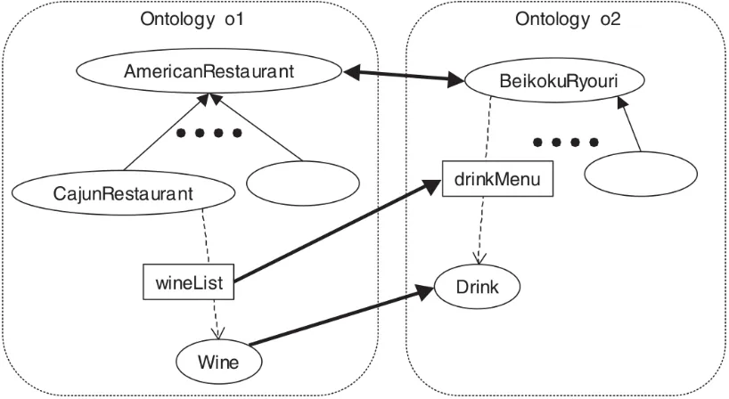
Figure 2.12 shows an example of Mapping. Both ontologies, o1and o2, represent
knowledge in the Restaurant domain. Ontologyo1encodes that knowledge in the
con-text of American restaurants, whereas ontologyo2does this in a Japanese context. The
bold arrows represent the map generated between the two ontologies. Figure 2.12b
presents an abstract view of the Mapping.
(a) Ontologies o1 and o2 with their mapping as bold arrows [14]
(b) ’Approximate ontology translation’ for the ontology mapping [38]
2.5 Ontology and Operations
2.5.3.4 Integration
Integration is the inclusion in one ontology of another ontology [23]. The integrated
ontology contains the knowledge of the original ontologies. Integration is different from
Merging as one of the ontologies is modified whereas Merging creates a new ontology.
An example of Integration is given in Figure 2.13. AandB, are the initial ontologies.
Integration results inBbeing ’absorbed’ intoA.
2.5 Ontology and Operations
2.5.3.5 Merging
Merging is the creation of a new ontology from two, possibly overlapping, source
ontologies [23]. The initial ontologies are not modified, with the new ontology
incorpo-rating the knowledge of both the ontologies.
Figure 2.14 shows an example of Merging. Sample ontology 1andSample ontology
2consist of information about the domain of Cars. A third ontology generated after the
Merging, as shown in Figure 2.14c, contains the knowledge of bothSample ontology 1
andSample ontology 2as a single ontology.
The ideas behind Ontology Merging can be traced back to the beginning of 1980s
[18]. The SMART algorithm was an early semi-automatic approach to Ontology Merging
and Alignment [54] . The PROMPT algorithm was an improvement of SMART and during
its development various Ontology Merging operations were identified [55].
Mathematical frameworks have been applied to Ontology Merging. Merging has been
done using Formal Concept Analysis (FCA-MERGE) [66]. Also, Category theory [33] has
been applied towards merging and Simple PushOut (SPO) in algebraic graph
transfor-mation [48] has been used to merge ontologies. Description Logic (DL) based merging
of Concrete and Fuzzy ontologies has also been accomplished [41].
An ontology integration process has been proposed in which two ontologies are
merged by generating an ontology intersection containing the maximum number of
entities contained in the input ontologies and their corresponding non-contradictory
axioms [69]. CODE [26] is a fully automated system that aims at preserving the source
ontology knowledge. It uses natural language processing in combination with a
se-mantic matching approach, along with scenario-based rules to make sure the merging
process is accurate. While being very comprehensive, CODE is a holistic process - taking
into account all aspects of the source ontologies including Class, Property and Instance.
While this is powerful, it is not useful for a more lightweight approach where only the
Classes of given ontologies need to be analyzed. It is a quite involved and cumbersome
process - going through multiple stages to acquire a merge, and would be difficult to
2.5 Ontology and Operations Thing Vehicle ancestor-of cycle is-a car is-a bicycle is-a motorcycle is-a sedan is-a cab is-a wagon is-a bus is-a
(a)Sample Ontology 1about Car
Thing Automobile ancestor-of Sedan is-a bus is-a wagon is-a taxi is-a brogham is-a Limousine is-a Shooting_brake is-a truck is-a
(b)Sample Ontology 2about Car
Thing Vehicle ancestor-of Car/Automobile is-a cycle is-a Bus is-a Limousine is-a Sedan is-a Cab/Taxi is-a Wagon is-a Shooting_brake is-a truck is-a is-a brougham is-a is-a bicycle is-a motorcycle is-a
(c) Merged Ontology
2.5 Ontology and Operations
Recently, Cloud-based ontology matching has been provided as a Service for
inte-gration and interoperability resolution primarily focused on biomedical systems [16].
A novel approach, but as the system has been built for a distributed architecture of a
cloud, it would be difficult to extract and incorporate the technique for a more restrictive
environment, such as a traditional, localized desktop system.
Also, ATOM base algorithm has been proposed that takes two ontologies and merges
them using an equivalence mapping [61]. A very clear and consistent terminology is
presented for the ATOM algorithm and lays down the foundations for developing similar
algorithms. Equivalence mapping is clearly defined and applied. A major drawback of
the algorithm is that it is limited to an IS-A relationship; it does not take into account
other possible relationships.
Table 2.2 presents the various operations and approaches described in the earlier
sections. This table compares the various works explored earlier on the basis of whether
user intervention is required, the type of relationship that is being used in the work (if
explicitly stated) and in the last column of the table, if the work is based on a
Design-Time or Run-Design-Time approach.
2.5 Ontology and Operations
Work Automated Relationship Place
[Noy and Musen, 1999]
(SMART) [54]
7 - Design-Time
[Noy and Musen, 2000]
(PROMPT) [55]
7 - Design-Time
[Stumme and Maedche,
2001] (FCA-MERGE) [66]
7 - Design-Time
[Hitzler et al., 2005] (Cate-gory theory) [33]
7 -
-[Raunich and Rahm, 2011] (ATOM) [61]
3 IS-A Design-Time
[Fudholi et al., 2014] (CODE) [26]
3 - Design-Time
[Mahfoudh et al., 2014] (Al-gebraic SPO) [48]
3 IS-A Design-Time
[Wu, 2014] (CODE) [26] 7 - Design-Time
[Amin et al., 2015] (Cloud-based) [16]
7 - Design-Time
[Kumar and Harding, 2015] (Description Logic) [41]
7
IS-A
TYPE-OF
PART-OF
Design-Time
Chapter 3
A New Method of Ontology
Combination
3.1
Overview
This chapter covers the problem statement of this thesis and the proposed
method-ology as the solution. The specific details of the methodmethod-ology are developed thoroughly.
The corresponding Combine algorithm is covered comprehensively in the later sections.
3.2
Problem Statement
The interactive approach for RE, outlined in Section 2.4 above, uses a single ontology
for modeling the domain requirements [73]. This can be further enhanced by acquiring
knowledge from other domains. Multiple ontologies can be brought together for this
purpose, enabling the approach to acquire additional knowledge from diverse domains.
Various operations on ontologies were covered in Section 2.5.3. Among these
ap-proaches, mathematical frameworks [66] [33] [48] require formulating the ontologies
into mathematical structures such as lattices and fuzzy structures. This requires an
3.3 Ontology Combination
required. While bringing mathematical precision to the merging process, the present
mathematical approaches lose flexibility and would fall short in performance during a
dynamic use of such approaches.
All semi-automatic approaches [54] [55] [66] [33] [69] [16] [41] require human
inter-vention at important stages of the merging process. Dynamic combination of
ontolo-gies, needed during run-time, should not require any human intervention. Any
tech-nique requiring user decisions during the merge process would defeat the purpose of
interactive RE as the focus of the user needs to be on gathering requirements rather
than merging ontologies. Also, in order to merge ontologies in this manner, the user
will need to have an in-depth knowledge of the merging process. For the purpose of a
software customization system, this should not be required and this, ideally, should be
transparent to the user. The user should not be required to know about ontologies or
of the process of merging ontologies; this should be taken care of in the background of
the interactive system without involving the user.
Furthermore, all of them are design-time operations. As such, they cannot be applied
to an interactive mode of knowledge extraction.
This thesis proposes a dynamic run-time operation of Ontology Combinations which,
by overcoming these limitations, can enhance interactive RE immensely.
3.3
Ontology Combination
As outlined in Section 2.5, existing approaches are mainly focused on ‘deep’ merges
of ontologies. Classes, relations, etc (some or all attributes of ontologies) are sought to
be merged. RE does not need this as Requirements Artefacts are usually discrete items
brought together to form a new system. An artefact is usually defined as a specification
of a physical piece of information that is used or produced by a software development
process [64]. RE needs ontologycombinationsso that new Requirements Specifications
can be generated quickly from different ontologies. Reasoning should be relatively quick
3.4 Example
entire structure of an ontology does not need to be merged.
Ontology Combination is similar to Ontology Merging but not the same operation. It
is different as ontologies being combined together might not share any ideas except for
the need of creating a joined ontology that might serve an entirely different purpose
from that of the original two ontologies.
3.4
Example
A general example can be used to demonstrate Ontology Combinations. Figure 3.1
shows aPizzaontology. It has, among other concepts, aFoodconcept. This concept is
further extended to concepts likePizza,IceCream,PizzaToppingetc. Now, another
on-tology can also contain information about food items such as theFoodontology shown
in Figure 3.2. This ontology contains a conceptEdibleThing. EdibleThingis refined into
different types of consumable items such asDessert,SweetFruitetc. If both these
on-tologies are combined, then a reasoning system based on thePizzaontology can take
advantage of the knowledge available in the Food ontology. A good instance of this
would be in creating new and unexpected pizza topping combinations for ordering
Piz-zas like a topping ofSweetFruit on aSpicyPizza. Figure 3.3 shows one possible pair of
3.4 Example
3.4 Example
3.4 Example
3.5 Proposed Methodology
3.5
Proposed Methodology
The methodology of performing an Ontology Combination is detailed in this section.
Terminology used is presented in Section 3.5.1 Definitions. Then the steps are
delin-eated. The summary is shown in Figure 3.4.
3.5.1
Definitions
Many similar notations for Ontologies exist in research literature. For this discussion,
an ontology is defined as a tuple:
O
i= (C
i,R
i,I
i,A
i)
where
C
iis the set of concepts,R
iis the set of relationships between the concepts,I
iis the set of instances,A
iis the set of axioms.K
RE is a RE Knowledge Base holding ontologies and their instances specializedto-wards the acquisition of requirements.
R
iandA
iare specific toO
iandI
iis part ofK
REand therefore will not be considered here.
Instances of ontologies will be assumed to honor the ontological evaluations after the
combination. It is assumed that all the ontologies are consistent before the beginning
of the combination process. Only concepts,
C
i, are needed for the combination and willbe analyzed here.
For the sake of brevity and simplicity, a combination of only two ontologies will be
delineated here. Starting with primary ontology
O
p = (C
p,R
p,I
p,A
p), a secondaryontology
O
s = (C
s,R
s,I
s,A
s), is selected fromK
RE. The steps taken to combine them3.5 Proposed Methodology
3.5.2
Step 1: Generate Correspondences
A set ofconcept correspondencesis defined as the set of (match) mapping between
two ontologies [61]. Given two concepts,
p
∈
C
pands
∈
C
s, a concept correspondencet
, is defined as an ordered pair(
p,
s
)
of a primary ontology conceptp
and a secondaryontology concept
s
[61]. Eacht
is characterized by a type selected fromequivalence,is-a and inverse-isa [61]. An equivalence correspondence is defined as a
correspon-dence where
p
ands
represent the same concept; an is-a correspondenceis definedas a correspondence where
p
is a subclass ofs
and an inverse-isa correspondence isdefined as a correspondence where
s
is a subclass ofp
[61]. Anis-a correspondenceisan oriented correspondence from a source concept to a target concept and expresses
anis-arelationship between them [61]. Aninverse-isa correspondenceis similarly
de-fined as the source concept being a ’superclass’ of the target concept [61]. Here, a set
of concept correspondences,
T
, will be used to identify the concepts in primary andsecondary ontologies.
T
will be used to generate the links between them inStep 2.3.5.3
Step 2: Generate Relationships
On the basis of the type of correspondences, relationships can be generated for the
links that tie the ontologies together.
3.5.4
Step 3: Check consistency of combined ontology,
O
cThe combined ontology,
O
c, obtained afterStep 2, will then be checked forconsis-tency using a suitable reasoner.
3.5.5
Step 4: Validation of
O
cA simple reasoning test can be performed to ensure that the link produced is valid
3.5 Proposed Methodology
Ontology-based requirements elicitation can be then be carried out [75] using the
combined ontology Oc. After this, if a suitable set of requirements has not yet been
obtained, this process can be iterated over again. The above steps can be iterated over
as many times as needed until a satisfactory set of requirements is gathered.
As the use of this methodology matures, existing ontologies can be modified and
newer ones can be added to
K
RE. Over time, such a methodology would yield a maturecollection of ontologies which would help in refining requirements even further, leading
to a less ambiguous and a detailed set of Requirements Deliverables.
The next section, covering the Combine algorithm, gives the details of the algorithms
3.5 Proposed Methodology
is now
Perform Requirements Elicitation using Primary Ontology,
Ontologies
Oi Oj Ok ...
Create Combined Ontology
Generate Correspondences
Generate Relationships
Consistency check of combined ontology,
Validation of Step 3:
Step 4: Step 2: Step 1:
Oc Oc
Combined Ontology, Oc
Requirements Elicitation Knowledge Base, KRE
Have the Requirements
Deliverables been satisfactorily
completed?
Yes
No
Oc Op
Oc
Detach previously combined ontologies, if needed Op
Start
3.6 Design of Algorithms
3.6
Design of Algorithms
3.6.1
Overview
The Combine algorithm is called during the process of RE for a SPL, represented by
the ontology,OSPL. Another ontology,Oi, from the RE Knowledge Base,KRE, is given as
input to the algorithm to perform the combination.
The algorithm uses the following:
• WordNet [13] - is a lexical database for the English language, often described as a
combination of a dictionary and thesaurus.
• Java WordNet Library (JWNL) [7] - is a free and open-source Java API for accessing
WordNet.
• Apache Lucene [2] - is a free and open-source information retrieval Java library.
• SimMetrics [12] - is a free and open-source Java library of similarity and distance
metrics for strings.
The Combine algorithm is composed of smaller algorithms - SelectLink,
GetCorre-spondences, GetRelationship, FindRelationshipJWNL and GetHighestCM - all of which
are described in this section. The SelectLink algorithm is called initially with string,
strSPLLea f Nodeof the leaf node,Vl inOSPL and the ontology to be combined,Oi. The
al-gorithm then calls the GetCorrespondences alal-gorithm to getCorrespondences, if they
exist, between strLea f Nodeand any node in Oi. The GetCorrespondences algorithm in
turn, calls the GetRelationship algorithm which tries to find the relationships (IS-A,
TYPE-OF, and PART-OF). It does this through the use of the FindRelationshipJWNL algorithm,
which uses the JWNL API for WordNet. The GetHighestCM algorithm is used to determine
theCorrespondencewith the highestConfidence Measurein a given set of Correspon-dences. The SelectLink algorithm returns a Correspondencewhich is used to linkOSPL
and Oi together. This enables the two ontologies to be linked together dynamically,
algo-3.6 Design of Algorithms
rithm can be called as many times as needed to combine other ontologies inKRE with
the mainOSPLontology.
3.6.2
SelectLink
algorithm
The SelectLink algorithm is shown below:
Algorithm 1SelectLink
Input: strSPLLea f Nodeis string for the concept of the leaf nodeVl inOSPL
Input: Oiis ontology that is to be combined
Output: cHighest is aCorrespondencethat will linkOSPLandOi together
1: c←0/ .set ofCorrespondences
2: for eachnode∈Oi do
3: c←c∪GetCorrespondences(strSPLLea f Node,node.label)
4: end for
5: cHighest←GetHighestCM(c)
6: returncHighest
The input for the SelectLink algorithm is the string for the concept of the leaf nodeVl
inOSPL,strSPLLea f Node, and the ontology that is to be combined,Oi. It returns as output,
a Correspondence c, which contains the node in Oi and the relationship that will link
OSPLandOi together.
The loop in Line 2 to Line 4 iterates over all the nodes in Oi to find out if there is
a correspondence between the node and strSPLLea f Node. This is done by calling the
GetCorrespondences algorithm (Section 3.6.3). All correspondences are collected into
the set ofCorrespondences,c. TheCorrespondencewith the highestConfidence
Mea-sureis selected by calling the GetHighestCM algorithm in Line 5. Confidence Measure
is described in GetHighestCM algorithm section (Section 3.6.6). ThisCorrespondence
3.6 Design of Algorithms
3.6.3
GetCorrespondences
algorithm
The GetCorrespondences algorithm is shown below:
Algorithm 2GetCorrespondences
Input: strSPLis string for the concept of the leaf nodeVl inOSPL
Input: strIis the string for the concept fromOi
Output: cis aCorrespondence
1: ifstrSPL=strIthen . same string
2: c.Relationship ←IS-A
3: c.CM=0
4: returnc
5: end if
6: tokensSPL←0/
7: tokensI←0/
8: cw←0/
9: strSPL←Lucene.StopWordsFilter(strSPL) 10: tokensSPL←Lucene.Tokenize(strSPL)
11: strI←Lucene.StopWordsFilter(strI)
12: tokensI←Lucene.Tokenize(strI)
13: for eachwSPL∈tokensSPLdo . first pass - try to find Anchor Word 14: for eachwI∈tokensI do
15: if0.0≤SimMetrics.JaroWinkler(wSPL,wI)≤0.1then
16: wAnchorWord←shortestOf(wSPL,wI)
17: ifsizeof(tokensSPL)=sizeof(tokensI)=1then .only one word
18: c.Relationship←IS-A
19: returnc
20: end if 21: end if 22: end for 23: end for
24: for eachwSPL∈tokensSPLdo .second pass 25: for eachwI∈tokensI do
26: cw←cw∪GetRelationship(wSPL,wI)
27: end for
28: end for
29: cwHighest←GetHighestCM(cw)
30: if(cw.size()≤1)and(cwHighest.RelationshipFound=true)then
31: c=cwHighest
3.6 Design of Algorithms
33: ifwAnchorWordthen
34: ifstrSPL.length>strI.length then .more ’generic’ concept
35: c.Relationship←IS-A
36: c.CM=0
37: else ifword beforewAnchorWord instrSPL=word beforewAnchorWord instrI=
VERB)then
38: c.Relationship←PART-OF
39: c.CM=0
40: end if
41: else .No relationship has been found
42: c.Relationship=NU LL
43: end if
44: end if
45: returnc
The GetCorrespondences algorithm tries to determine the correspondence between
two concepts,strSPLfromOSPLandstrIfromOi, through two levels of matches:
• String Level Match is done on the entire two strings to figure out the relationship
betweenstrSPLandstrI. Line 1 to Line 5 and Line 13 to Line 23 are the String Level
Matching parts in the algorithm.
• Word Level Match is done on individual words of the strings to figure the
relation-ship between them. Line 24 to Line 28 are the Word Level Matching parts in the
algorithm.
The input to the GetCorrespondences algorithm arestrSPLwhich is the string for the
concept of the leaf nodeVlinOSPLandstrIwhich is the string for the concept fromOi. The
output of the algorithm is aCorrespondencewhich contains the relationship between
the two input strings and theConfidence Measurefor that relationship.
A check is done in Line 1 to see if the two strings are equal and if they are, then the
relationship is considered of type IS-A and the algorithm returns this as a
Correspon-dencewithConfidence Measureof 0. From Line 9 to Line 12, the Apache Lucene library is used to filter for stop words and to tokenize the input strings. The first pass through
the two strings, from Line 13 to Line 23, tries to find anAnchorWord. An AnchorWord
3.6 Design of Algorithms
utilizing the Jaro-Winkler distance implemented in the SimMetrics library. If the words
are similar and there is only one word in both the strings, then the relationship is of
type IS-A and the correspondence has been found.
If the relationship has not been found yet, then a second pass is made through the
string tokens, from Line 24 to Line 28. Each word in tokensSPL is compared with each
word intokensI to determine the relationship between them by calling the
GetRelation-ship algorithm. All the Correspondences obtained are put into the set of
Correspon-dences, cw. TheCorrespondencewith the highest Confidence Measureis selected by calling the GetHighestCM algorithm in Line 29.
If no relationship has yet been found, then a relationship is sought based on the
wAnchorWordusing the logic between Line 32 to Line 44. IfstrSPLis longer thanstrI, then
strI represents a more ’general’ concept and thus the relationship is of type IS-A. On
the other hand, if the words before thewAnchorWord - both instrSPLandstrI are ’verbs’
(for example, ’Select book name’ and ’Find book author’ - here ’Select’ and ’Find’ are
verbs), then the relationship is assumed to be of type PART-OF.
If no relationship has been found yet and there was nowAnchorWord, then no
3.6 Design of Algorithms
3.6.4
GetRelationship
algorithm
The GetRelationship algorithm is shown below:
Algorithm 3GetRelationship
Input: word1 andword2are strings
Output: cwis a correspondence between the two words
1: word1POS←0/
2: word2POS←0/
3: cwAll←0/
4: JWNL.Initialize()
5: word1POS←JWNL.GetPOS() .get all Parts-of-Speech for word1
6: word2POS←JWNL.GetPOS() .get all Parts-of-Speech for word2
7: for each p1∈word1POSdo
8: for each p2∈word2POSdo
9: if p1=p2then
10: r←FindRelationshipJWNL(SYNONYM)
11: ifr6=NU LLthen
12: cw.Relationship←IS-A
13: cw.ConfidenceMeasure←r.Depth
14: cwAll←cwAll∪cw
15: end if
16: r←FindRelationshipJWNL(HYPERNYM)
17: ifr6=NU LLthen
18: cw.Relationship←TYPE-OF
19: cw.ConfidenceMeasure←r.Depth
20: cwAll←cwAll∪cw
21: end if
22: r←FindRelationshipJWNL(HYPONYM)
23: ifr6=NU LLthen
24: cw.Relationship←TYPE-OF
25: cw.ConfidenceMeasure←r.Depth
26: cwAll←cwAll∪cw
27: end if
28: if p1=p2=V ERBthen
29: r←FindRelationshipJWNL(TROPONYM)
30: ifr6=NU LLthen
31: cw.Relationship ←TYPE-OF
32: cw.ConfidenceMeasure←r.Depth
33: cwAll←cwAll∪cw
3.6 Design of Algorithms
35: end if
36: r←FindRelationshipJWNL(HOLONYM)
37: ifr6=NU LLthen
38: cw.Relationship←PART-OF
39: cw.ConfidenceMeasure←r.Depth
40: cwAll←cwAll∪cw
41: end if
42: r←FindRelationshipJWNL(MERONYM)
43: ifr6=NU LLthen
44: cw.Relationship←PART-OF
45: cw.ConfidenceMeasure←r.Depth
46: cwAll←cwAll∪cw
47: end if
48: end if
49: end for
50: end for
51: cwHighest←GetHighestCM(cwAll)
52: returncwHighest
The GetRelationship algorithm takes as input two strings,word1andword2and returns
as output aCorrespondence Word,cwwhich contains the relationship between the two
words and the correspondingConfidence Measure.
The JWNL library is initialized in Line 4. In Line 5 and Line 6, all the possible
Parts-Of-Speech values for the given words are found, as it is possible for a word to be a
NOUN or a VERB depending on the context. For example, the word ’act’ can be used
as a NOUN as in "Act II of Hamlet" and as a VERB - "acting in a movie". In the following
part of the algorithm, from Line 7 to Line 50, all the Parts-Of-Speech found for each of
the word is iterated through and if a match is found for the Part-Of-Speech, then the
relationship and the Confidence Measure for that relationship is determined by
call-ing the FindRelationshipJWNL algorithm with different WordNet Pointer Types such as
SYNONYM, MERONYM, etc.
Since there can be multiple Parts-Of-Speech for the two words, theCorrespondence
with the highestConfidence Measureis obtained by calling the GetHighestCM algorithm
3.6 Design of Algorithms
The following table summarizes the various WordNet Pointer and Relationship types:
WordNet Pointer Type Relationship Type
SYNONYM (SIMILAR) is-a
HYPONYM,
HYPERNYM,
TROPONYM
type-of
HOLONYM,
MERONYM
part-of
3.6 Design of Algorithms
3.6.5
FindRelationshipJWNL
algorithm
The FindRelationshipJWNL algorithm is shown below:
Algorithm 4FindRelationshipJWNL
Input: start andendare JWNL.IndexWords
Input: typeis the type of relationship being inquired about
Output: ris a JWNL.Relationship
1: JWNL.Synset[]startSenses=start.getSenses()
2: JWNL.Synset[]endSenses=end.getSenses()
3: JWNL.Relationshipr←NU LL
4: for eachs1∈startSensesdo .Check all against each other to find a relationship 5: for eachs2∈endSensesdo
6: RelationshipList=JWNL.RelationshipFinder(startSenses[i],endSenses[j],type) 7: ifRelationshipList6=NU LLthen
8: r←RelationshipList.get(0)
9: returnr
10: end if 11: end for 12: end for
13: returnNU LL .Relationshiptypenot found forstart andend
The FindRelationshipJWNL algorithm takes as input two JWNL.IndexWords, start and
end. It also needs the type of relationship that needs to be figured out (as shown in the
table in Section 3.6.4), designated as type. If the requested relationship is found, the
algorithm returns as output aJWNL.Relationship,rwhich contains the relationship
be-tween the two words and the correspondingConfidence Measure. Otherwise, it returns
aNU LLvalue.
The WordNet senses for the two input words are retrieved in Line 1 and Line 2.
Be-tween Line 4 and Line 12, the senses for each word are iterated over to find a match
fortype. If a match is found, then the algorithm returns that relationship. Otherwise, a
3.6 Design of Algorithms
3.6.6
GetHighestCM
algorithm
The GetHighestCM algorithm is shown below:
Algorithm 5GetHighestCM
Input: cis set ofCorrespondences
Output: cHighest is aCorrespondencethat has the highestConfidence Measure
1: cHighest.RelationshipFound← f alse
2: ifc.size()6=0then
3: cHighest←c.get(0)
4: for eachc1∈cdo
5: ifc1.RelationshipFound=truethen
6: ifcHighest.ConfidenceMeasure≥c1.ConfidenceMeasurethen
7: cHighest←c1 8: end if
9: end if
10: end for 11: end if
12: if(c.size()>1)and(cHighest.CM>CM_THRESHOLD)then
13: cHighest.Relationship←NU LL
14: end if
15: returncHighest
If more than one word match/relationship has been found (Line 2), then the
Confi-dence Measure (CM)is used to resolve the relationship in the loop from Line 4 to Line 10. This measure represents the depth between the two words/concepts and comes directly
from the JWNL library. The closer theConfidence Measureis to 0, the closer it is assumed
to the ‘real’ relationship. A Confidence Measureof 0 represents a direct match. If two
(or more) relationships have the sameConfidence Measure, the last one is selected as
the relationship between the two words. Similarly, if there are multiple word
correspon-dences between two strings, theConfidence Measureis used to determine the eventual
relationship between the two strings.
In Line 12 if theConfidence Measurefound is greater then theCM_THRESHOLD, then
it is determined that no relationship has been found. WordNet provides senses between
two words that can very deep, and as such can provide very obscure relationships,
3.6 Design of Algorithms
usage of the language.CM_THRESHOLDis thus used to ensure that no arcane or vague
relationships are provided as output by the algorithm.
3.6.7
Time Complexity
Note: The discussion below follows the convention where the symbol V is used as a
shorthand to denote|V|(the number of vertices in a graph) in the context of asymptotic
notation for Graph Algorithms [19].
For the Combine algorithm,
Viis the set of nodes in the ontologyOi,
mis the number of words intokensSPL,
nis the number of words intokensI
The Combine algorithm is composed of the following algorithms: SelectLink ,
GetCor-respondences , GetRelationship , FindRelationshipJWNL and GetHighestCM algorithms.
Since WordNet is a finite set of words and their senses, interaction with the WordNet
database in GetRelationship and FindRelationshipJWNL algorithms is assumed to be of
constant time for the purpose of determining the time complexity of the Combine
algo-rithm.
The GetHighestCM algorithm contains the for loop in Line 4 which iterates over a
given set of all theCorrespondences to find out the highestConfidence Measure. This
algorithm is primarily called from two places - in the SelectLink algorithm to determine
theCorrespondenceto linkOSPLand Oi together and in the GetCorrespondences
algo-rithm to obtain the correspondences between strSPL and strI. When GetHighestCM is
called in the SelectLink algorithm, the set ofCorrespondencescan hold, at maximum,
aCorrespondencefor each node inOi, which isVi. When the algorithm is called from the
GetCorrespondences algorithm, the set ofCorrespondencescan hold, at maximum,mn
Correspondences.
![Figure 2.1: Software Product Line Engineering [59]](https://thumb-us.123doks.com/thumbv2/123dok_us/1391474.1171865/21.612.155.493.109.366/figure-software-product-line-engineering.webp)
![Figure 2.2: Service Oriented Architecture [22]](https://thumb-us.123doks.com/thumbv2/123dok_us/1391474.1171865/22.612.236.415.457.584/figure-service-oriented-architecture.webp)
![Figure 2.3: Requirements Engineering processes [68]](https://thumb-us.123doks.com/thumbv2/123dok_us/1391474.1171865/25.612.124.534.112.315/figure-requirements-engineering-processes.webp)
![Figure 2.5: Pseudo code for requirement evaluation process [73]](https://thumb-us.123doks.com/thumbv2/123dok_us/1391474.1171865/29.612.155.494.154.512/figure-pseudo-code-requirement-evaluation-process.webp)
![Figure 2.6: Interactive Requirements Elicitation system [73]](https://thumb-us.123doks.com/thumbv2/123dok_us/1391474.1171865/30.612.117.539.255.514/figure-interactive-requirements-elicitation-system.webp)
![Figure 2.8: Ontology as a UML model [27]](https://thumb-us.123doks.com/thumbv2/123dok_us/1391474.1171865/32.612.175.473.408.654/figure-ontology-as-a-uml-model.webp)
![Figure 2.10: Ontology Matching [42]](https://thumb-us.123doks.com/thumbv2/123dok_us/1391474.1171865/34.612.130.485.394.622/figure-ontology-matching.webp)
![Figure 2.14: Ontology Merging [39]](https://thumb-us.123doks.com/thumbv2/123dok_us/1391474.1171865/39.612.211.541.97.636/figure-ontology-merging.webp)
