Development of Waja Based CNGDI Passenger Vehicle Rear
Platform Component
Barkawi Sahari1, Mohd. Fauzy Ahmad2, V. Chelliah3, 1Universiti Putra Malaysia (UPM), 2Proton Berhad, 3Petronas.
Abstract: The development of a compressed natural gas vehicle (CNGV) for passenger car is of interest nationally and
worldwide, particularly with the rise in petrol prices. The main components of a CNGV are the body, engine and transmission and fuel storage. For the vehicle body development, many aspects need to be considered. These are the on board fuel storage locations, crashworthiness, strength and vibration characteristics. For petrol vehicle, the shape of the fuel storage can be designed to fit the space available underneath the vehicle body structure. However, for CNGV, the shape of the gas storage is always cylindrical. Hence, the vehicle body structure is to be designed to fit the cylindrical storage tanks underneath the platform as well as the passengers above it. In addition, the ergonomic passenger compartment and crashworthiness need also to be considered. This paper presents the analysis of a rear platform of Waja body to fit the CNG tanks. The result for the crash characteristics of the CNG rear platform is presented. It is compared with that of the corresponding petrol platform and discussed. The effect of the CNG rear platform on the natural frequency and stiffness of the vehicle body is also presented and discussed.
Keyword: Natural Gas Vehicle, Rear Platform, Crashworthiness
NOTATION
E – Young’s modulus t – time in milliseconds ν – Poisson’s ratio σ – direct stress σy –yield stress ε – strains
ρ – material mass density y – displacement KT – total energy KE – kinetic energy KI – internal energy
H – hour glass energy (distortion energy due to deformation without change of volume)
Sij – deviatoric stress tensor (= ij ij kk
3
1
σ
δ
−
σ
)δij – Kronecker delta (= 1 for i = j, = 0 for i ≠ j) k- structural stiffness
p ij
d
ε
- incremental plastic strain componentsp
d
ε
- incremental equivalent plastic strain F – crush forceINTRODUCTION
The automotive body platform is a complex structure. The platform forms the basic size and shape of the car. Cars of different makes and models can use the same platform and drive train (engine, transmission, and final drive components), suspension and steering. For simplicity of identification, the platform is divided into three parts - engine compartment, front platform and rear platform as shown in Fig. 1 (1). The engine compartment refers to the part covering the engine to the firewall, while the front platform refers to the part from the firewall to the rear passenger seat excluding the firewall and the rear platform is the structure from the rear passenger seat to the rear end. In an attempt to design crash energy absorber for automotive vehicles, many research works on crashworthiness has concentrated on metallic tubes (2), composite tubes and cones (3, 4, 5, 6, 7, 8, 9, 10, 11). These works shows that the crashworthiness and energy absorption depends on the geometry and material properties.
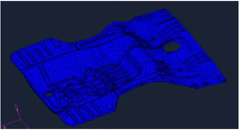
In the design of CNGV platform, the shape of the tank has to be cylindrical. Hence, the platform has to fit the tank. On the other hand, for gasoline vehicle, the shape of the fuel tank is designed to fit the available space. It can be seen that a slightly different approach need to be used. The main characteristics to be determined included static strength, torsion and bending stiffness, first mode vibration natural frequency and crashworthiness analysis (12). There are three methods that can be used; namely closed form analytical, experimental and finite element (3, 4, 5, 6, 7, 8, 9, 10 and 11). The closed form analytical method is normally limited to simple geometry, whereas experimental method is usually expensive and only being carried out for verification. Hence finite element method offers practical alternative to experimental method. In the present work, a CNGV rear platform component without reinforcement (platform B) and with reinforcement (platform C) shown in Fig. 2, is developed based on similar platform for gasoline without reinforcement (platform A) as shown in Fig. 1. Finite element is used for the crash analysis of the rear platform subjected to lateral impact. The results obtained were compared with the platform for gasoline vehicle. The objective of the work is to achieve CNGV platform with similar, if not better, crash characteristics compared with that of gasoline. For this purpose, the internal crash energy absorbed was used as the criteria. In the present work, the CNG platform is considered acceptable when it has similar or better internal energy absorbed compared with the gasoline platform.
THEORETICAL BACKGROUND
In crash analysis, generally it involves impacting an elastic plastic structure of known mass, m, moving with a specified velocity, v, against a rigid object, such as a rigid wall. At the onset of impact, the structure will come into contact with the rigid wall. The kinetic energy, KE of the structures is given by
Eqn. 1
mv
22
1
KE
=
This kinetic energy will be transferred into strain energy. At the beginning of impact, only elastic deformation occurs. The stress distribution is often non uniform, especially for complex structures like car platform, and pockets of highly stressed areas may occur. As the crash proceeds, more kinetic energy is released (results in reduction of v) and this cause plastic deformation starting from the high stressed regions. As the crash proceeds further, v will further reduce with time and increases the structural deformation and distortion. To account for distortion without change of volume, hourglass energy, H is used. For most cases, the value of H is small and negligible. Some part of the structure may fail plastically. The total energy in the system becomes:-
Eqn. 2
KT
=
KE
+
KI
During crash, total energy is conserved and hence:-Eqn. 3
k
y
k
y
H
2
1
mv
2
1
2 p p 2 e e 2+
+
=
The plastic deformation only occurs when the yield criteria of the material is satisfied. For the present study, von Mises yield criteria is used. That is yield occur when:-
Eqn. 4 eq
S
ijS
ij y2
3
σ
=
=
σ
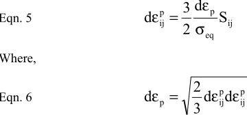
Eqn. 5 ij eq
p p
ij
S
d
2
3
d
σ
ε
=
ε
Where,
Eqn. 6 p
d
ijpd
ijp3
2
d
ε
=
ε
ε
For analysis involving crash, as in the present case, the elastic displacement ye is very small compared with plastic displacement yp. Also, in the present anslysis, a ‘good’ mesh is developed that resulted in H also very small. Hence, neglecting elastic energy and H, the internal energy expression reduces to:-
Eqn. 7
KI
=
k
py
2pIn integral form, Eqn. 7 can be written as
Eqn. 8
KI
=
∫
k
py
pdy
=
∫
Fdy
pWhere F is the crush force and is given by
Eqn. 9
F
=
k
py
pHence, from Eqn. 8 it can be seen that the internal energy can be obtained from the area under the graph of crash force, F versus plastic displacement, yp. From Eqn. 7, it can be seen that KI is very much dependent on yp. The crashworthiness of a structure is often represented by a graph of KI versus displacement. The main objective of the analysis is to achieve maximum KI in the shortest possible displacement.
FINITE ELEMENT MODELLING, MATERIALS AND BOUNDARY CONDITIONS
The shape of the platform under investigation is as shown in Fig. 1. A typical finite element mesh is shown in Fig. 2. The platform is made of mild steel with the properties given in Table 1. The boundary condition used in the present analysis is one of the side is fully restraint while the the other is subjected to a rigid wall impact. The mass of the rigid wall is 950 kg and its initial velocity is 50 km/h (13.9 m/s) in the y (rear to front) direction For all cases, the analyses were carried out for a maximum time of 100.0 ms. This was to ensure that all the kinetic energy has been completely dissipated. The CNGV is designed with the specification as shown in Table 3.
RESULT AND DISCUSSION
Finite element results
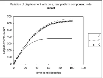
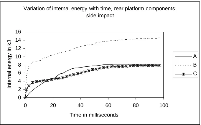
The crash behaviour is best described by looking at the shape of platform deformation at various time interval from t = 0 ms to t = 100.0 ms at time interval of 50 ms. For the rear impact, Fig. 3 shows the variation of crash displacement (mm) with time (ms) for platforms A, B and C. It can be seen that the displacement first increases linearly with time up to 10 ms and thereafter the behaviour becomes nonlinear. Crash initiate at the impacted side with the platform crumple in the direction of velocity. It was found that there is no displacement normal to the platform plane suggesting that crumpling occurs in the same plane as the platform and no intrusion to the passenger compartment as a result of the crash. From Fig. 3, it can be said that platform A is superior compared with platforms B or C. The kinetic energy absorbed is shown in Fig. 4. It shows that all the impact energy is fullu dissipated within 100 ms. The internal energy absorbed is shown in Fig. 5. It can be seen that platform B achieved the highest energy compared with either platforms A or C. This shows that the reinforcement design is sufficient to absorb higher energy compared with the platform without reinforcement and the base platform. The numerical values of the results are shown in Table 2. From Table 2, platform B with the reinforcement is suitable to be used.
Experimental results
Table 4. It can be seen that the performance of the CNGV vehicle is similar to the gasoline base platform. In some cases namely, higher torsional stiffness, higher bending stiffness, lower first 3 modes of natural frequencies. The first mode natural frequency which is 41.9 Hz is within acceptable values and it is torsional which is desirable for handling and stability. Hence, the developed CNGV platform and body is acceptable.
CONCLUSIONS
The objectives of the work has been achieved. The behaviour of rear platform component for CNGV has been carried out. From the results obtained, it can be conlcuded that, changing the shape of the rear platform do not change the performance of the platform. In some cases the peformance is improved. Hence, the newly developed platform for CNGV is suitable for installation of the tanks outside the vehicle and at the same time improves its strength and dynamic performance. Also, the earlier hypothesis that if the shape of a part of the structure is modified and replaced with another part having the same characteristics, the resultant structural characteristics remains the similar.
ACKNOWLEDGEMENTS
The authors would like to thank The Malaysian Ministry Of Science, Technology And Innovation for sponsoring this research under project IRPA 03-02-04-0562-PR0030/10-08 Vehicle Architecture and Integration, Universiti Putra Malaysia and their staff, members of the CNG/DI Engine and Transmission IRPA research group and their
organisation; UKM, UM, UiTM, UTM, UTP, PROTON and PRSS. The authors would also like to thank the
following researchers for their help and assistance; Jasmi B. Abdul Rahman, Norwazan Bt. Abdul Rahim, Siti Marhainis Bt. Abu Mansor, Lo Woon Chek, Norfaizah Bt. Mohd. Arsad, Safwati Bt. Ahmad, Mohd. Nor Izham B. Abd. Aziz, Muhammad Mujahid B. Azni, Mohd. Idzwan B. Kamaruzaman, Nurul Izzah Bt. Ab. Rahim, Mohd. Faisal B. Ismail.
REFERENCES
1. Halderman. J.D., and Mitchell, Jr. C.D. “Automotive chassis systems”, Second Edition, Prentice-Hall Inc. 2000 2. Lee, S., Hanh, C., Rhee, M. and Oh, J. “Effect of triggering on the energy absorption capacity of axially compressed
aluminium tubes”, Materials and Design 20, 1999, 31-40.
3. Mahdi, E., Hamouda, A.M.S., Sahari, B.B., “Axial and lateral crushing of the filament wound laminated composite curved compound system.” Jnl. Advanced Composite Materials; Volume 11 Number 2; 2002, 171-192.
4. Elgalai, A. M., Mahdi, E., Hamouda, A. M. S., Sahari, B. B., “Crushing response of composite corrugated tubes to quasi-static axial loading”, Composite Structures 66, 2004, 665-671.
5. Mahdi, E., Hamouda, A. M. S., Sahari, B. B., Khalid, Y. A., “Experimental quasi-static axial crushing of cone-tube-cone composite systems”, Composites: Part B 34, 2003, 285-302.
6. Mahdi, E., Hamouda, A. M. S., Sahari, B. B., Khalid, Y. A., “On the collapse of cotton/epoxy tubes under axial static loading”, Applied Composite Materials 10:, 2003, 67-84.
7. Mahdi, E., Sahari, B. B, Khalid, Y. A., Hamouda, A. M. S., “Effect of hybridisation on crushing behaviour of carbon/glass fibre/epoxy circular cylindrical shells”, Journal of Materials and Processing Technology 132(1-3), 2003, 49-57.
8. Mahdi, E., Sahari, B. B., Khalid, Y. A., Hamouda, A. M. S., “Crushing behaviuor of cone-cylinder-cone composite system”, Int. Jnl. Mechanics Of Advanced Materials and Structures, Vol. 9, No. 2, 2002, 99-118.
9. Mahdi, E., Hamouda, A. M. S., Sahari, B. B., Khalid, Y. A., “Effect of material and geometry on crushing behaviour of laminated conical composite shells.” Jnl. Applied Composite Materials; 9: 2002, 265-290.
10. Mahdi, E., Sahari, B. B., Hamouda, A. M. S., Khalid, Y. A., “An Experimental Investigation Into Crushing Behaviour Of Filament Wound Laminated Cone-Cone Intersection Composite Shells”, Journal Of Composite Structures, Vol. 51, No. 3, 2001, 211-219.
11. Assad A Khalid, Sahari, B. B., Khalid, Y. A., “Effect of tube geometry on the energy absorption of cotton and glass fibre/epoxy composites”, Journal, Institution of Engineers, Malaysia, Vol. 61, No. 1, 2000, 13-22.
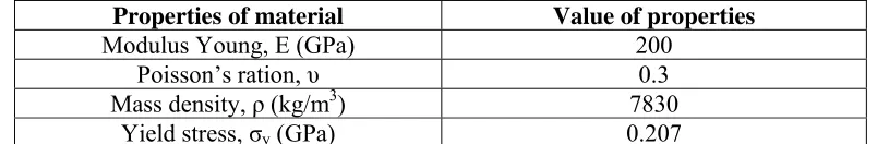
Table 1 Mechanical property
Properties of material
Value of properties
Modulus Young, E (GPa)
200
Poisson’s ration,
υ
0.3
Mass density,
ρ
(kg/m
3) 7830
Yield stress,
σ
y(GPa)
0.207
Table 2 Result of crash analysis
Lateral impact
Rear platform
component types
Characteristics
Internal Energy absorption (kJ)
A
Gasoline tank
8.0
B
CNG with reinforcement
14.5
C
CNG without reinfocement
7.8
Table 3: Tank specification for 3 Tank model CNG vehicle
Bil Dimension Location
Tank
Weight
(kg)
Gas
Weight
(kg)
Total
Weight
(kg)
GGE
Range
(km)
Ground
Clearance
(mm)
1
∅
280 mm
x 594 mm
Boot/luggage
compartment
(Rear)
14.0 4.63 18.63 1.8 88.57 300
2
∅
240 mm
x 820 mm
Boot/luggage
compartment
(Middle)
15.0 4.12 19.12 1.6 78.73 180
3
∅
240 mm
x 920 mm
Boot/luggage
compartment
(Front)
16.0 6.43 22.43 2.5 123.01 180
Total
45.0 15.18 60.18 5.9 290.31
Table 4 Experimental results
Type of
test
Waja
Gasoline
CNGV
With Glass
No Glass
No Glass
Bending
Stress point 1 (Mpa)
113.5
135.4
121.7
Stress point 2 (Mpa)
90.7
103.5
72.6
Stress point 3 (Mpa)
61.2
62.3
60.8
Stress point 4 (Mpa)
59.3
62.32
58.55
Stiffness (N/mm)
18691.58
11876.98
19230.7
Torsion
Stiffness (Nm/deg)
20237.44
13586.55
17313.0
Dynamic First mode frequency
38.7 Hz,
torsion
44.05 Hz,
torsion
41.9 Hz
(torsion)
Second
mode 42.8
Hz,
bending
46.02 Hz,
bending
(Bending)
45 Hz
Third
mode
84.3
Hz,
Fig. 1: Design concept for rear CNGV platform (platform C and D)
Variation of displacement with time, rear platform component, side impact
0 100 200 300 400 500 600 700
0 20 40 60 80 100 120
Time in milliseconds
D
isp
la
ce
m
e
n
ts
i
n
m
m
A
B
C
Fig. 3 Side impact crash analysis results for rear platform
Kinetic energy side impact rear platform component
0 20 40 60 80 100 120 140 160 180 200 220
0 20 40 60 80 100
Time in milliseconds
K
in
e
ti
c
ene
rg
y
i
n
J
o
u
les
A
B
C
Variation of internal energy with time, rear platform components, side impact
0 2 4 6 8 10 12 14 16
0 20 40 60 80 100
Time in milliseconds
In
te
rnal
ener
g
y
i
n
k
J
A
B
C
Fig. 5. Side impact crash results for rear platform
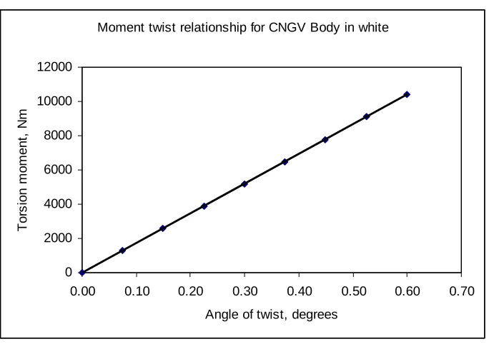
Moment twist relationship for CNGV Body in white
0 2000 4000 6000 8000 10000 12000
0.00 0.10 0.20 0.30 0.40 0.50 0.60 0.70
Angle of twist, degrees
T
o
rs
ion m
o
m
e
nt
, N
m