Transactions of the 17th International Conference on Structural Mechanics in Reactor Technology (SMiRT 17) Prague, Czech Republic, August 17 –22, 2003
Paper # B01-2
Development of a Finite Element Based Probabilistic Tool
Ronald F. Kulak and Paul V. Marchertas
Argonne National Laboratory, USA
ABSTRACT
The assessment of the safety of nuclear reactors and their structures is usually based on deterministic analysis that uses best estimate data. Data such as material properties are oftentimes not known and standard handbook values are chosen. Even when precise data is known from tests performed before construction, aging effects can significantly change their values. Finite element solutions may be dependent on solution parameters chosen by the analysts, which can affect the computed results. In most structural integrity assessments of beyond design basis accidents, loadings present the highest degree of uncertainty. Under these conditions, purely deterministic analysis is far from sufficient in providing adequate assessment of structural integrity. Physics based probabilistic analysis is needed.
During the past quarter century, a tremendous effort has been devoted to the development of finite element based software resulting in sophisticated proprietary and commercial products. More recently, commercial probabilistic analysis engines have become available. This paper describes the methodology used to couple the deterministic finite element based code NEPTUNE, which was developed at Argonne National Laboratory, with the commercial probabilistic code ProFES, which was developed by Applied Research Associates, Inc., in order to provide a tool for performing probabilistic analysis of reactor structures subjected to design-basis and beyond-design-basis loadings. A sample problem is presented to illustrate the use of this new tool. The problem is a reinforced concrete slab subjected to blast loading. Key material properties for the concrete and reinforcing steel and the diameter of the reinforcing steel were chosen as random variables. The strain in the reinforcing steel was chosen as the response variable. Based on ductility limits for the reinforcing bars, a limit function was defined and the probability for failure over a loading pressure range was determined.
KEY WORDS: Probabilistic Finite Element Analysis, Structural Integrity, Reinforced Concrete, Blast Loading
INTRODUCTION
In order to assure the public that nuclear power plants are safe, regulatory bodies throughout the world require structural integrity assessments of these plants and their structural components. The assessments are performed for both design basis accidents (DBA) and beyond design basis accidents (BDBA). Because of the complexity needed to treat the physics that occurs during these accidents, analysts have relied on using sophisticated computer codes to model the accidents and their affects on nuclear structures. The development of sophisticated structural analysis computer codes began in the early 1970s and have been under continuous development since then. The majority of these codes are deterministic codes in the sense that all the physical parameters used to define geometry, material properties, loadings, etc. as well as the computational parameters uses in the analyses have fixed values. These values usually are chosen by the analysts/engineer as best estimate values. Thus, the results from these analyses do not take into account the range of variation of these parameters or the affect that different combinations of the parameters can have on the conclusions drawn from the analyses. The probabilistic aspect of the parameters has been neglected.
During the past quarter century, a tremendous effort has been devoted to the development of nonlinear finite element (FE) based software resulting in sophisticated proprietary and commercial products. It is now realized that the probabilistic nature of the important variables must be taken into account to provide a more realistic assessment of safety issues. One approach is to embed a probabilistic analysis engine into the deterministic structural analysis codes and thus provide both a deterministic and probabilistic analysis capability. However more recently, commercial probabilistic analysis engines have become available. So a second approach is to couple an existing structural analysis engine with a commercial probabilistic analysis engine, and this was the path that was followed here.
This paper describes the methodology used to couple a proprietary, deterministic finite element based code, NEPTUNE [1], which was developed at Argonne National Laboratory, with a commercial probabilistic code ProFES [2], which was developed at Applied Research Associates Inc., in order to provide a tool for performing probabilistic analysis of the structural integrity of reactor structures subjected to beyond design basis loadings. The majority of the work was to develop software that could couple the deterministic structural analysis code, NEPTUNE, with the probabilistic code ProFES.
described. Finally, an illustrative example is presented to show how a probabilistic analysis is performed for a concrete slab subjected to a blast load.
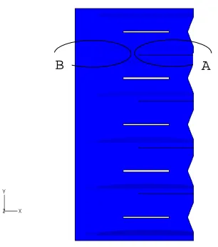
The finite element probabilistic tool developed here was used by researchers at the Lithuanian Energy Institute (LEI) to perform probabilistic analysis on some of the safety systems of the RBMK-1500 reactors located at the Ignalina Nuclear Power Plant in Lithuania. The developed methodology was applied to the analysis of a whipping group distribution header, which results from a guillotine break, and subsequent impact with the adjacent building wall [3] and an adjacent group distribution header [4]; this is a postulated accident for the Ignalina Nuclear Power Plant RBMK-1500 reactors.
DETERMINISTIC FINITE ELEMENT CODE, NEPTUNE
The NEPTUNE code is a three-dimensional finite element code designed to address the nonlinear structural response of nuclear reactor structures and their components to normal and off-normal loadings. The code can handle loadings that are either static or transient dynamic. NEPTUNE can simulate problems that involve the following: (1) plate/shell structures, (2) continua, (3) concrete, (4) reinforced concrete, (5) beams, (6) bars, (7) contact mechanics (e.g., impact, sliding, contact and release), (8) buckling, and (9) silent boundaries. One major feature of NEPTUNE is the capabilities to treat nonlinear problems such as occur in reactor safety issues. The computational engine uses the central difference algorithm for transient dynamic problems and the dynamic relaxation algorithm to solve nonlinear static problems. The code is written in FORTRAN and can run on the following platforms: PC, SUN, HP, SGI and IBM RS6000. A recent version of the code [5] can run on high performance parallel computing platforms such as a Linux cluster computer and a network of distributed workstations. The code has been benchmarked against closed form solutions and scale model tests of reactor structures and components.
NEPTUNE has been described in many open literature publications. The code has been used to assess the structural integrity of U.S. and Russian containments (steel and reinforced concrete) [6, 7], RBMK Accident Localization System (ALS) [8], primary vessels [9], reactor vessel topside closures [10], equipment transfer locks [11] and pipe whip impact [12, 13] among others. Since NEPTUNE has been extensively used to evaluate U.S. and foreign reactor designs to loadings from severe accidents, adding a probabilistic capability will further enhance this deterministic analysis tool.
PROBABILISTIC ANALYSIS CODE, ProFES
Probabilistic methods [e.g., 14-16] provide a means to assess the effects of uncertainties of the material properties, component geometry data, loads and modelling parameters in predicting structure reliability and performance. ProFES is a commercial probabilistic engine that can be coupled to a deterministic finite element code such as NEPTUNE. It is a menu driven interactive software tool and operates in Windows 9x/NT/XP and Unix environments.
The first step in using ProFES is to import the deterministic finite element model, which consists of material properties, nodal coordinates, element connectivity, boundary conditions and loads. From the original input file, the random variables must be defined. The following variables can be assigned as random variables: material properties, geometric parameters, nodal coordinates, loads, modelling parameters, loads and other model parameters. Each selected random variable is then assigned a distribution and distribution parameters. The following probability distributions are available for the analysts to choose from: normal, log-normal, uniform, triangular, exponential, constant, hat-shaped, beta and Weibull. Either the standard deviation or the coefficient of variation can be chosen as a distribution parameter. The next step is to define the response variables, which are the requested output quantities and are contained in the NEPTUNE output file. For most problems the analysts is interested in determining the probability of failure and this can be defined by limit states. An additional feature of ProFES is the “system event” that is used to create a new limit state that is a function of existing limit states.
With the random variables, response variables, limit states and system events defined, the next step is to perform the probabilistic analysis. There are severable methods available for performing the probabilistic analysis. Monte Carlo Simulation (MCS) is the basic probabilistic method used to compute statistics of response variables and probabilities for limit states and system events. MCS is a brute force method in which values for the random variables are chosen to cover their probability distribution functions (PDF) and random combinations of the values are used in deterministic calculations. According to Shooman [17], the percentage error is related to the number of simulations, n, and the estimated failure probability,
Welding bead (6pointsnode)
, according to the following:
f
f
np
p
error
200
(
1
)
/
%
=
−
intensity is exacerbated when the deterministic finite element analysis is also computationally intensive, such as encountered during nonlinear analysis for the structural integrity assessment of NPPs,
Other less computationally intensive methods have been developed and are part of the suite of probabilistic methods available in ProFES. The number of simulations can be reduced by using Importance Sampling (IS), which only samples in the region around the most probable point (MPP). The First Order Reliability Method (FORM)/Second Order Reliability Method (SORM) first performs a search for the MPP, then fits a linear/second-order surface at the MPP and then uses approximations to estimate the probabilities of the limit states. The Response Surface/MCS (RS/MCS) method fits a response surface about the mean of the random variables and then computes response variable statistics and limit state probabilities using MCS. The Adaptive Response Surface method (ARS) is a variant of the Response Surface/MCS method in which the response surface is fit about the MPP.
COUPLING CODE, pnglue
The major part of the work was the development of the coupling code, pnglue. The code was programmed in Perl because it is well suited to extracting information from one text file and generating another (which is in fact what it was designed for - Practical Extraction and Report Language). Since it is an interactive software tool, the analyst works from a graphical user interface (GUI). Initially a NEPTUNE input file is processed (imported) by pnglue to provide ProFES with information as to which values are available in the current model. This is necessary so that the user can browse and select properties via the GUI provided by ProFES. Most of the time when pnglue is running, it is modifying the identified random variables in the NEPTUNE input file according to the values determined by ProFES and to retrieve the response variables from the NEPTUNE output file for probabilistic analysis by ProFES. At the end of computations, ProFES prepares an analysis report giving the results of the probabilistic analysis. Figure 1 graphically shows the interactions among the user and the three codes.
Figure 1. Flow diagram among User, ProFES, pnglue and NEPTUNE.
The first step in using ProFES with a local copy of NEPTUNE is to start ProFES. Then, the analyst imports the existing FE model into ProFES using the import dialog box. Next, the probabilistic model must be setup. This is done by selecting random variables, specifying distributions, setting correlations, designating dependent variables, and creating limit states. Random variables are selected from the Variables Menu. The following quantities from NEPTUNE FE input files are available as random variables: loads, material properties, element properties and geometric properties. Using the Define Random Variable dialog box, the distribution functions and distribution parameters for each random variable are specified. The corresponding values from the FE input file will be modified by pnglue prior to each model call (i.e., deterministic FE calculation) according to the values selected by ProFES.
The Response Variable dialog box is used to identify the selected response variables. The response variables correspond to requested output quantities (e.g, displacements, velocities, accelerations, stresses, strains, etc.). The NEPTUNE format for a typical requested output consists of an output-code field and a descriptor field. For example, the requested output for the axial strain of rebar layer 4 in element number 25 is as follows:
250412EL25RL4_Exx
Analysis Parameters
Specifications
NEPTUNE Format
Probabilistic Analysis
Random Variables
Response Variables
pnglue
Input File
Output
File NEPTUNE
Results
User
ProFES Neutral
Format Input
X Y
CL CL
SS SS
1
25
The output-code field, 250412, identifies the axial strain of rebar layer 4 of element 25 as a requested output quantity. The descriptor field, EL25RL4_Exx, is subsequently used as a title in the NEPTUNE output file and plots. In order to make this requested output a response variable, the descriptor field is changed to the following, which is understood by ProFES:
250412PF+E,E,1,25
The descriptor field has been change to PF+E,E,1,25 in which: the first indicator, PF, is a hook that lets pnglue know that the output data stream belongs to a response variable; the second indicator, +, tells pnglue to search for the maximum positive value; the third indicator, E, specifies that this is an elemental quantity; the fourth indicator, E, indicates it is a strain value; the fifth indicator, 1, indicates that the strain is along the x-axis; and the sixth indicator, 25, identifies the element number. Table 1 shows the entire set of indicators that are available to the analyst.
Table 1. Indicators for response variables
No. Indicator Meaning
1 PF ProFES Hook
2 [ - + _ ] Minimum, Maximum or Maximum Absolute value 3 [ N E ] Nodal or Elemental 4 , [ U S E ] Response Quantity
Displacement, Stress, Strain
5 ,[ 1 2 3 ] Response Axis
6 ,# Node or Element Number
After each deterministic finite element run, pnglue retrieves the values for the response variables from the output file for processing by ProFES after all the deterministic runs have been completed.
The Define Limit State dialog box is used to define the desired limit states (e.g., maximum strain, maximum displacement, etc). The System Events dialog box is used to create a new limit state that is a function of existing limit states. The final step is to select a probabilistic analysis method from the following: Monte Carlo Simulation, Importance Sampling, Response Surface/MCS, Adaptive Response Surface, First Order Reliability Method, Second Order Reliability Method or First Order/Second Moment Method.
ILLUSTRATIVE EXAMPLE
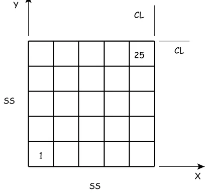
The following example illustrates the use of this newly developed tool. The problem considered is a rectangular, simply supported, reinforced concrete slab that is loaded by an explosive pressure. Since this problem is presented only for the purpose of illustration and not for a rigorous engineering analysis, strain-rate effects and other failure modes were not considered. The finite element model for one-quarter of the slab is shown in Fig. 2 and consists of 25 reinforced quadrilateral plate elements and 36 nodes. The left and lower sides are simply supported and the right and upper sides are on symmetry lines. The full plate is
1040 mm by 1040 mm and is 65 mm thick. Orthogonal reinforcing steel is located in the top and bottom layers of the slab. The reinforcement ratios in the top (pressure loaded face) and bottom of the slab are 0.006. The rebars in the top and bottom of the slab have a cross section area of 12.57 mm2 (diameter
= 4 mm) and have a pitch of 31.64 mm. The reinforcing steel was assumed to have a Young’s modulus of 2.3 x 10⁵ N/mm,2 a yield stress of 570
N/mm2 and an ultimate strength of 702 N/mm.2 A
multilinear stress-strain curve, which is given in Table 1, was used to represent the elastoplastic response of the rebars. The concrete was assumed to have a Young’s modulus of 16 KN/mm,2 a Poisson’s
ratio of 0.18, a compressive strength of 43 N/mm2
and a tensile strength of 4.3 N/mm.2 The nonlinear
compressive behaviour of the concrete also is shown in Table 1. The loading was assumed to be a step
Table 1. Concrete and Steel Material Properties
Reinforcing Steel Concrete
Stress (N/mm2) Strain (mm/mm) Stress (N/mm2) Strain (mm/mm)
570 0.0025 19.4 0.00118
678 0.0053 34.0 0.0025
702 0.20 40.0 0.0035
42.0 0.0045
43.0 0.0055
For this illustrative example, the following were chosen as random variables: concrete compressive strength, rebar yield stress and rebar diameter, which is reflected in the cross sectional area.
Table 2. Random variables, variance and distributions
Variable Mean Standard
Deviation COV Distribution Compressive
Strength (N/mm2)
43 4.3 0.1 Normal
Yield Stress
(N/mm2) 570 63 0.11 Normal
Area of Rebars
(mm2) 12.57 1.26 0.10 Normal
The chosen response variable was the axial strain in the steel reinforcement located in element 25 (Fig. 2), which is the element at the center of the plate. Based on a limiting ductility of twenty times the yield strain,
ε
y, the limit state forthe reinforcing steel was chosen to be
ε
y≤
0
.
042
.Using Importance Sampling, a probabilistic analysis was performed to determine the probability of failure over the load range from 9 -17 N/mm2. The results are shown in Figure 3 where it is seen that below 9 N/mm2 the probability of
failure is 0 % and above 17 N/mm2 the probability of failure is 100 %. The probability of failure is 50% at a little over
13 N/mm2. Using the mean values for all random variables, Figure 4 shows the temporal variation of the axial strain of
the bottom rebar on the tension side for the 14 N/mm2 pressure load case. It is noted that a pressure loading of 9 N/mm2
causes the center of the plate to deflect about 65 mm, which is about equal to the thickness of the plate, And a loading pressure of 16 N/mm2 was sufficient to displace the center of the plate 115 mm, which is nearly twice the plate
thickness.
A B
-0.01 0 0.01 0.02 0.03 0.04 0.05
0 0.02 0.04 0.06 0.08 0.1 0.12
R
e
b
ar
S
tra
in
,
m
m/m
m
Time, sec
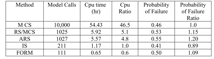
In order to compare computational times, several of the other analyses methods available in ProFES were exercised for the load case of 13 N/mm.2 Table 3 shows the cpu times, number of model calls (i.e., deterministic finite element
runs) and the predicted values for the probability of failure. Since the deterministic finite element computations dominant the cpu usage, Table 3 shows that the computational time requirements for the different methods is directly proportional to the number of model calls
.
The probability of failure predicted by MCS, RS/MCS, ARS, and IS were relatively close. The MCS was considered to be the benchmark with an estimated error of 2.2%. >From Table 3 it is seen that MCS is the most compute intensive.Table 3. Comparison of number of model calls, computational times and predicted probability of failure (Computer: Pentium 3, 700MHz)
Method Model Calls Cpu time
(hr) RatioCpu Probabilityof Failure Probabilityof Failure Ratio
M CS 10,000 54.43 46.5 0.46 1.0
RS/MCS 1025 5.92 5.1 0.53 1.15
ARS 1027 5.57 4.8 0.55 1.20
IS 211 1.17 1.0 0.41 0.89
FORM 111 0.65 0.6 0.50 1.09
SUMMARY
The need for physics based probabilistic analysis of nuclear power plant structures subjected to design and beyond design basis accidents has been realized. This need has been brought about by uncertainties in material properties, geometric parameters, loadings, aging effects and modelling parameters. To realistically determine the structural integrity of complex NPP structures subjected to extreme loads, large finite element models must be used. During the past quarter century, a tremendous effort has been devoted to the development of finite element based software resulting in sophisticated proprietary and commercial products. More recently, commercial probabilistic analysis engines have become available. This paper described the methodology used to couple the deterministic finite element based code NEPTUNE with the commercial probabilistic code ProFES in order to provide a tool for performing probabilistic analysis of reactor structures subjected to design-basis and beyond-design-basis loadings.
The deterministic finite element code and the probabilistic analysis code were seamlessly integrated with a coupling code written using the Pearl language. An example problem was presented to illustrate the new probabilistic capabilities. The problem was a reinforced concrete slab subjected to a blast load. The compressive strength of concrete, the yield stress of the reinforcing steel, and the cross-section area of the reinforcing steel were chosen as random variables. Based on a ductility ratio of twenty, a maximum strain of 4% for the reinforcing steel was chosen as the limit state, and the probability of failure for a range of reflected pressures was determined. A comparison of the compute times for the following five methods was made: Monte Carlo, Response Surface/Monte Carlo, Adaptive Response Surface, Importance Sampling and First Order Reliability Method. The Monte Carlo Method required the most compute time (54 hrs) and First Order Reliability Method required the least (0.65). The compute times were directly proportional to the number of deterministic finite element runs required by each method.
This new capability has been used by researchers at the Lithuanian Energy Institute to perform probabilistic analysis to address some of their reactor safety issues. LEI applied the developed methodology to the analysis of a whipping group distribution header, which results from a guillotine break, and subsequent impact with the adjacent building wall and an adjacent group distribution header; this is a postulated accident for the Ignalina Nuclear Power Plant RBMK-1500 reactors. This analysis required a large finite element model. Currently, LEI is applying the methodology to the thermal-mechanical analysis of steam distribution devices, which also employ large finite element models.
ACKNOWLEDGEMENTS
REFERENCES
1. Kulak R.F. and Fiala C., “Neptune a System of Finite Element Programs for Three Dimensional Nonlinear Analysis”, Nuclear Engineering and Design, 106, 1988, pp. 47-68.
2. Cesare M. A. and Sues R. H., “PROFES Probabilistic Finite Element System – Bringing Probabilistic Mechanics to the Desktop”, American Institute of Aeronautics and Astronautics, AIAA 99-1607, 1999, pp. 1-11.
3. Alzbutas, Robertas, Dundulis, Gintautas, Kulak, Ronald F., Marchertas, Paul V., “Reliability Analysis of Pipe Whip Impacts,” Transaction 17th International Conference on Structural Mechanics in Reactor Technology,
Prague, Czech Republic, August 17-22, 2003 (CD-ROM), Paper M268.
4. Alzbutas, Robertas, Dundulis, Gintautas, Kulak, Ronald F., “Finite Element System Modelling and Probabilistic Methods Application for Structural Safety Analysis,” KONBiN 2003, Gdynia, Poland, May 26-30, 2003, Paper B9.2.
5. Kulak, R.F., Pfeiffer, P.A. and Plaskacz, E.J., (1997)," Modeling of Containment Structures on High Performance Computers," Nuclear Engineering and Design, 174 (2), pp. 143-156.
6. Pfeiffer, P. A., Kulak, R. F., Kennedy, J. M., Marchertas, A. H., and Fiala, C. (1989) “Pretest Analysis of a 1:6-Scale Reinforced Concrete Containment Model Subject to Pressurization," Nuclear Engineering and Design, 115, 73-89.
7. Pfeiffer, P. A. and Kulak, R. F., 1995, “Structural Response of Rectilinear Containment to
Overpressurization,” Eds. C. Y. Wang, S. Kaneko, and R. F. Kulak, Fluid-Structure Interaction and Structural Mechanics 1995, ASME Publication PVP-Vol. 310, pp.141-159.
8. Dundulis, G. and Uspuras, E., “Non-Linear Analysis of the Ignalina NPP Accident Localization System Structural Integrity,” Transactions 16th International Conference on Structural Mechanics in Reactor
Technology, Washington DC, August 12-17, 2001, Paper # 1486.
9. Kulak, R. F. (1980) "Theory and Application of Three-Dimensional Treatment of Pool-Type Liquid-Metal Fast Breeder Reactor Components," Nuclear Technology, 51(3), pp. 378-387.
10. Kulak, R. F. (1980) "Three-Dimensional Analysis of Reactor Decks and Their Supports," Nuclear Technology, 51(3), 414-420.
11. Pfeiffer, P.A., Moran, T.J. and Kulak, R.F., (1997), "Structural Concerns in Dynamic Drop Loads on Transfer Lock Mechanisms," Ed., K.K. Panahi, Advances in Analytical, Experimental and Computational Technologies in Fluids, Structures, Transients and Natural Hazards, ASME Publication PVP-Vol. 355, pp. 163-173. 12. Kulak, Ronald F. and Narvydas, Evaldas (2001) “Validation of the NEPTUNE Computer Code for Pipe Whip
Analysis,” Transactions 16th International Conference on Structural Mechanics in Reactor Technology,
Washington DC, August 12-17, 2001, Paper # 1124.
13. Dundulis, G., Kulak, R., Marchertas, A., Narvydas, E., Petry, M., Uspuras E., “Evaluation of Pipe Whip Impacts on Neighboring Piping and Walls of the Ignalina Nuclear Power Plant”, Proc. of ICONE10 (CD version), 9 pp, Arlington, Virginia, USA April 14-18, 2002.
14. Melchers, R. E., Structural Reliability Analysis and Prediction, John Wiley & Sons, New York, 1999. 15. Cruse, T. A., ed., Reliability-Based Mechanical Design, Marcel Dekker, Inc., New York, 1997.
16. Haldar, A. and Mahadevan, S., Probability, Reliability, and Statistical Methods in Engineering Design, John Wiley & Sons, Inc., New York, 2000.