ABSTRACT
BRADHAM, ASHLEY ELIZABETH. Development of a System for Analysis and Selection of CBRN Boot Materials.(Under the direction of Dr. Roger Barker and Dr. Keith Beck.)
Current boots used for chemical, biological, radiological, and nuclear (CBRN) incidents provide good protection but are often heavy, uncomfortable and inflexible. There is a need for finding a new CBRN material, but the current standards for material resistance against threats like toxic industrial chemicals (TICs) do not use an approach that is similar to how CBRN boots are used in the field.
A new system was developed to expose and decontaminate materials multiple times to determine if a more lightweight flexible material could provide protection throughout the service life of a CBRN boot. Several materials were screened for their absorbance to a battery of TICs, and the results were compared to a rubber sample taken from a certified CBRN boot. Decontamination procedures were compared and the most efficient method was selected. The material that performed the best was subjected to one-day and four-day field simulation procedures. One-day in the field was defined as three exposures with decontaminations following each exposure.
Development of a System for Analysis and Selection of CBRN Boot Materials North Carolina State University
by
Ashley Elizabeth Bradham
A thesis submitted to the Graduate Faculty of North Carolina State University
in partial fulfillment of the requirements for the Degree of
Master of Science
Textile Chemistry
Raleigh, North Carolina 2011
APPROVED BY:
_____________________________ ______________________________ Dr. Don Thompson Dr. Ronald Baynes
_____________________________ _______________________________ Dr. Roger Barker Dr. Keith Beck
ii BIOGRAPHY
Ashley Elizabeth Bradham was born August 13, 1987 to Whit and Dena Bradham in Dunn, North Carolina. She has a younger sister, Emily Bradham. Ashley lived in Dunn throughout her childhood and graduated from Triton High School in 2005.
Following high school, she moved to Raleigh, North Carolina to attend North Carolina State University (NCSU). During her undergraduate career, she was awarded the Charles H. Stone Scholarship from the American Association of Textile Chemists and Colorists (AATCC). While pursuing her degree, she worked as a lab assistant for Tumbling Colors and a lab technician for HueMetrix. During the summer of 2008, she wrote a laboratory exercise on high internal phase emulsion, which was incorporated into an undergraduate polymer chemistry laboratory manual. She completed the University Scholars Program and was a textile student mentor. Ashley was a member and held leadership roles in the AATCC student chapter, Sigma Tau Sigma Textile Honors Fraternity, and Phi Psi Professional Textile Fraternity. She was also inducted into Phi Kappa Phi Honors Society in 2008. Along with school activities, she worked as a volunteer for Relay for Life, Rex Hospital, and the Katrina relief in Gulfport, Mississippi. In 2009, Ashley graduated Valedictorian and Summa Cum Laude with a Bachelor of Science degree in Polymer and Color Chemistry. At graduation, she was awarded the AATCC Outstanding College Graduate of the Year and the Chester H. Roth Honor Award.
iv ACKNOWLEDGEMENTS
I would first like to thank all the members of my committee for their support during my Master’s studies. To my Co-Chairs, Dr. Roger Barker and Dr. Keith Beck, I am so appreciative of all the guidance, encouragement, and advice you have given me during my research. Thank you for taking time out of your busy schedules to sit with me and discuss my questions and concerns. Dr. Beck, thank you for all of your analytical efforts and expertise that were such a critical part of this project. Dr. Don Thompson and Shawn Deaton, I am so grateful for the knowledge and support that you provided me and this research. I feel very fortunate to have learned from and worked with such kind and caring leaders. I would like to especially thank Cotton Incorporated for lending the use of their Accelerated Solvent Extractor, which helped to make the work for this project much more efficient.
The faculty and graduate students in TPACC have also been important to the completion of this research. Thank you for being there to help me work through problems and engineer special devices for the project. I have enjoyed the teamwork, and I appreciate the support.
v TABLE OF CONTENTS
LIST OF TABLES ... viii
LIST OF FIGURES ... ix
Chapter 1. Introduction ... 1
1.1 Purpose ... 1
1.2 Research Objectives ... 2
Chapter 2. Literature Review and Background ... 3
2.1 Toxic Industrial Chemicals ... 3
2.1.1. Standard Lists of Toxic Industrial Chemicals ... 3
2.1.2. Background on Selected Toxic Industrial Chemicals ... 5
2.1.2.1. Summary of TIC Properties ... 5
2.1.2.2. Acrolein... 6
2.1.2.3. Acrylonitrile ... 7
2.1.2.4. m-Cresol ... 7
2.1.2.5. Methyl Parathion ... 8
2.1.2.6. Morpholine ... 9
2.1.2.7. Sulfuric Acid ... 10
2.2 CBRN Boot Materials ... 10
2.2.1. Properties of Commercially Available CBRN Boots ... 10
2.2.2. Considerations for New CBRN Boot Materials ... 12
2.3 Exposure and Decontamination of CBRN Materials ... 13
2.3.1. Exposure ... 14
2.3.2. Decontamination ... 16
2.4 Standard Test Procedures for Chemical Protective Clothing ... 20
2.4.1. NFPA 1994 Standard ... 20
2.4.2. Standards for Material Resistance to Chemical Penetration ... 21
2.4.3. Wipe Methods ... 23
2.4.4. Gaps in Standard Test Procedures ... 26
2.5 Accelerated Solvent Extraction ... 28
2.5.1. Introduction ... 28
2.5.2. Advantages ... 30
vi
2.6 Chromatography ... 33
2.6.1. Gas Chromatography ... 33
2.6.2. Thermal Desorption ... 36
Chapter 3. Experimental ... 37
3.1 Experimental Approach ... 37
3.2 Chemicals and Instrumentation... 38
3.2.1. Chemicals ... 38
3.2.2. Extraction and Analytical Instruments ... 38
3.3 Procedures ... 39
3.3.1. Modified ISO 6530 Splash Test Screening ... 39
3.3.2. One-Day Field Simulation ... 43
3.3.2.1. First Exposure ... 43
3.3.2.2. First Decontamination ... 44
3.3.2.3. Second Exposure and Decontamination ... 47
3.3.2.4. Third Exposure and Decontamination ... 47
3.3.3. Four-Day Field Simulation ... 51
3.3.4. Wipe Test ... 51
3.3.5. Extraction Methods ... 52
3.3.5.1. Semi-Volatile TICs ... 52
3.3.5.2. Volatile TICs ... 54
3.3.5.3. Inorganic TIC ... 54
3.3.6. Analytical Techniques ... 55
3.3.6.1. GC/FID for Semi-Volatile TICs ... 55
3.3.6.2. TD/GC/FID for Volatile TICs ... 57
3.3.6.3. Titration for Sulfuric Acid ... 58
Chapter 4. Results and Discussion ... 59
4.1 Splash Test ... 59
4.2 Decontamination ... 61
4.3 One-Day Simulation ... 63
4.4 Four-Day Simulation ... 64
4.5 Wipe Test ... 67
Chapter 5. Conclusions ... 68
viii LIST OF TABLES
TABLE 2.1 SUMMARY OF SELECTED TICPROPERTIES ... 5
TABLE 2.2 EXTRACTION TIMES OF VARIOUS EXTRACTION TECHNIQUES ... 32
TABLE 2.3 SOLVENT USAGE OF VARIOUS EXTRACTION TECHNIQUES ... 32
TABLE 3.1ASEMETHOD DEVELOPMENT WITH LEATHER ... 53
TABLE 3.2GC/FIDCALIBRATION RESULTS FOR SEMI-VOLATILE TICS ... 56
TABLE 3.3GC/FIDCALIBRATION RESULTS FOR VOLATILE TICS ... 58
TABLE 3.4ACID DETERMINATION BY TITRATION ... 59
TABLE 4.1SPLASH TEST MATERIALS SCREENING ... 60
TABLE 4.2RESIDUAL TICS AFTER ONE EXPOSURE AND DECONTAMINATION ... 62
TABLE 4.3ONE DAY SIMULATION RESULTS FOR RUBBER AND LEATHER C ... 64
TABLE 4.4FOUR DAY SIMULATION RESULTS FOR RUBBER AND LEATHER C ... 66
TABLE 4.5WIPE RESULTS FOR RUBBER AND LEATHER CSAMPLES ... 68
TABLE A.1RESIDUAL MORPHOLINE IN LEATHER BAFTER DECONTAMINATING WITH DIFFERENT SCRUBBING MATERIALS ... 85
ix LIST OF FIGURES
FIGURE 2.1ACCELERATED SOLVENT EXTRACTOR (ASE®)200SCHEMATIC ... 29
FIGURE 3.1 BENT NON-STERILE SYRINGE NEEDLE ... 40
FIGURE 3.2 NEEDLE ATTACHED TO SYRINGE ... 40
FIGURE 3.3ATTACHMENT OF MATERIAL TO GUTTER WITH CLIPS ... 42
FIGURE 3.4EXPERIMENTAL SETUP FOR MODIFIED ISO6530SPLASH TEST ... 42
FIGURE 3.5NEW LAB-SCALE SPLASH SIMULATION DEVICE ... 44
FIGURE 3.6DECONTAMINATION DEVICE ... 46
FIGURE 3.7SPONGE THAT ATTACHES TO DECONTAMINATION DEVICE ... 46
FIGURE 3.8DISC PLACEMENT IN THE RESTRAINING RING OF PENETRATION CELL ... 48
FIGURE 3.9MATERIAL SAMPLE LOADED INTO PENETRATION CELL ... 48
FIGURE 3.10 ASSEMBLED PENETRATION CELL ... 49
FIGURE 3.11 PENETRATION TEST APPARATUS ... 49
FIGURE 3.12SYRINGE USED TO DELIVER CHALLENGE CHEMICAL TO PENETRATION CELL .... 50
FIGURE 4.1RUBBER EXPOSED TO MODIFIED ISO6530ACROLEIN SPLASH TEST ... 61
FIGURE 4.2 LEATHER EXPOSED TO MODIFIED ISO6530ACROLEIN SPLASH TEST ... 61
FIGURE 4.3M-CRESOL ON RUBBER SAMPLE ... 67
FIGURE 4.4M-CRESOL ON LEATHER C ... 67
FIGURE A.1RUBBER SAMPLE AFTER SCRUBBING FOUR MINUTES WITH A ROUGH BRUSH ... 82
FIGURE A.2LEATHER SAMPLE AFTER TWO MINUTES WITH A ROUGH BRUSH ... 83
FIGURE A.3RUBBER SAMPLE AFTER TEN MINUTES OF SCRUBBING WITH A SPONGE ... 84
1 Chapter 1. Introduction
1.1Purpose
Chemical, Biological, Radiological, and Nuclear (CBRN) first responders and other hazmat teams rely on their clothing ensembles for protection. The gear used by these responders includes boots that must resist not only a wide range of chemical challenges, but also have puncture, abrasion, and flash fire resistance. To meet the high level of protection required by CBRN boots, responders have adopted a boot made from dense rubber materials. These rubber boots are typically heavy and inflexible, and can cause physiological stress and blisters from skin abrasion. Discomfort resulting from CBRN boots reduces the length of time a responder can spend in the field. First responders that choose a lighter, thinner CBRN boot often find that the stability and traction of this design is limited. A new material for these boots would increase the comfort and work performance of CBRN responders.
2 candidates for CBRN use, there is a need for new test methods that involve multiple chemical exposures and decontamination procedures that mimic the use of the materials in the field.
Part of the need for new test procedures includes determining the best performing and most efficient decontamination procedure. There is little information available on the efficiency of the current military decontamination procedure. Investigating new decontamination solutions and approaches could lead to better removal of a chemical challenge with minimal material damage.
1.2Research Objectives
The objective of this research was to create a laboratory based system for analysis and selection of new materials for use in construction of reusable tactical CBRN boots. The system would mimic the use of CBRN boots over a typical service life, and determine if a candidate material is rugged enough to maintain an appropriate level of protection before being implemented into a prototype for certification.
Project tasks included:
1. Development of methods to expose and decontaminate a material sample in a way that simulates the use of a CBRN boot. Specific questions addressed by this task are as follows:
a. How many chemical exposures and decontamination cycles are typical during the CBRN boot service life?
3 c. What is the current decontamination procedure used by CBRN
responders? Is this current decontamination procedure adequate, or is there a new procedure that could be more effective?
2. Development of extraction and analytical methods that could determine the amount of a challenge chemical remaining in a material sample after exposure and decontamination.
Completing these tasks would provide a system for analyzing the performance of materials for CBRN use that is unlike any current standard test method. New methods will aid in determining if a more flexible, comfortable boot material could survive multiple uses in the field. Boot manufacturers could benefit from these methods because they assist in the selection of a new material before the development of a boot prototype for official certification. The overall objective of this research is to provide a more comprehensive test system that may lead to the next generation tactical CBRN boots that provides more comfort and stability for the user.
Chapter 2. Literature Review and Background 2.1Toxic Industrial Chemicals
2.1.1. Standard Lists of Toxic Industrial Chemicals
4 industrial processes around the world and may be available in large quantities.[1,2] TICs could be hazardous to human health due to their chemical classification, such as a carcinogen, teratogen, corrosive agent, nerve agent, etc. They may also be hazardous due to their reactivity. For example, a TIC could be a chemical that is highly explosive, flammable or combustible.[2] Toxic industrial chemicals that are used against the military pose a very different threat from typical weapons such as firearms. The properties of TICs make them capable of mass casualties if large quantities were accidently spilled or if they were used in a terrorist attack.[1,2] They can be spread over a wide range, reside on many different surfaces and remain there for an extended period of time.[3] TICs may be harmful in many different forms, such as liquid pool, gas or fine aerosols.
5 2.1.2. Background on Selected Toxic Industrial Chemicals
2.1.2.1. Summary of TIC Properties
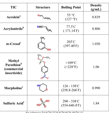
Some properties and characteristics of the selected TIC are listed in Table 2.1. The boiling points of some TICs were references for the development of gas chromatography (GC) methods. The density of a TIC was helpful in calibrating the pump used for delivering the TIC to a material sample (section 3.3.1).
Table 2.1 Summary of Selected TIC Properties
TIC Structure Boiling Point Density
(g/mL)
Acroleina 53 °C
(127 °F) 0.839
Acrylonitrileb ( 171.1477.3̊ C ̊ F) 0.806
m-Cresolc 203̊ C
(397.40̊ F) 1.030
Methyl Parathiond (commercial
insecticide)
>109°C
(>228°F) 1.06
Morpholinee (258.8-266126 - 130̊ C ̊ F) 0.990
Sulfuric Acidf (554-640.4290 - 338̊ C ̊ F) 1.84
6 2.1.2.2. Acrolein
Acrolein is rated as a medium hazard on the OSHA TICs list and is a chemical challenge in the NFPA 1994 standard.[1,2] This TIC is a concern because it is used in the manufacturing of many different products. It is a common intermediate in the manufacturing process of some pharmaceuticals, resins and other chemical compounds.[5,12] Acrolein is used as a biocide for killing weeds in agriculture and used to remove algae in water. It has been added to methyl chloride refrigerant to act as a warning agent due to acrolein’s strong odor.[5,12] Acrolein is produced when wood, tobacco and many other items are burned. It can also be found in leather tanning processes and may be incorporated into chemical weapons.[5,12,13]
7 2.1.2.3. Acrylonitrile
Acrylonitrile is listed as a medium hazard on the OSHA TICs list and is also a chemical challenge in the NFPA 1994 standard.[1,2] Acrylonitrile has been used as a monomer and co-monomer in the production of polymers. It has also been used in the
manufacturing of other chemical compounds such as pharmaceuticals, dyes and fumigants.[5]
OSHA regulations state that over an average workday, a person cannot be exposed to
more than 2 ppm of acrylonitrile in the air or 10 ppm in a 15-minute period.[7,16] OSHA also
states that there should be no human contact with liquid acrylonitrile. Adsorption of acrylonitrile
through the skin can cause skin irritation and toxic symptoms that seem to be a result of changes
in the central nervous system. The dermal LD50 for a rabbit is 63mg/kg.[7] It is a known
mutagen and suspected human carcinogen. Nervous system cancer develops in animals exposed
to acrylonitrile.[5,7] In July 2010, the Covington Fire Department and other responders assisted
with a spill of acrylonitrile from a barge collision on the Mississippi river.[17] The acrylonitrile
was being transported for use in polymerization processes.
2.1.2.4. m-Cresol
m-Cresol is used as a solvent for polymers in making products such as resins. It is also
used in the production of explosives and fumigants.[5] m-Cresol can cause chemical burns, and is
poisonous through skin adsorption, inhalation, and ingestion.[5,8] The lower dermal LD50 for a
rabbit is 620mg/kg.[8] It is known to have human mutagenic effects and may be a carcinogen.
The OSHA exposure limit during a typical eight- hour work day is 5 ppm.[8] In 2005, two trains
8
and the train was also carrying liquid cresol and sodium hydroxide.[18,19] Although chlorine
gas was a threat to more people because it was released in the air, there was concern for the
corrosive hazards of the liquid chemicals for responders at the scene of the accident. Another
incident involving a rail car occurred in North Charleston, South Carolina in 2008. Firefighters
and hazmat teams responded to a leak of cresol from a rail car that released a total of 5
gallons.[20] The transportation of m-cresol in large quantities makes it a concern for first
responders.
2.1.2.5. Methyl Parathion
9 and death.[9] In 2007, 50 gallons of methyl parathion was spilled at a plant making insecticide for cotton crops. People living within 5,000 feet of the plant were evacuated and government agencies responded to the spill.[23]
2.1.2.6. Morpholine
Morpholine has been used as an intermediate in the production of rubber, optical
brighteners, pharmaceuticals, agricultural products, dyes, resins, etc.[24] It has also been used in
some leather treatment and tanning processes.[25-27] The International Programme on Chemical
Safety recommends that leathers contaminated with pure morpholine should be discarded to
avoid skin contact.[22] Enhanced leathers were one of the materials considered for use in the
new CBRN boots. Morpholine was chosen as a TIC to make sure new leather materials could
withstand the harshness of morpholine and similar chemicals.
Morpholine is hazardous because it can cause burns through all routes of exposure. Skin
burns can occur if morpholine is absorbed.[10] If ingested, there can be burns to the
gastrointestinal tract, and burns can occur in the respiratory tract if it is inhaled. The permissible
exposure limit to morpholine during an eight-hour work day is 20 ppm according to OSHA.[10]
The dermal LD50 for a rabbit is 500µL/kg. There have been several reports of morpholine spills.
In 1981, Bremerton, Washington firefighters were called to a depot where a 55-gallon drum
containing morpholine was punctured.[28] Firefighters cleaned the area using protective clothing
10
2.1.2.7. Sulfuric Acid
The inorganic selection for this project was sulfuric acid. It is listed as high in the hazard index of the OSHA TICs list.[2] Sulfuric acid is produced in such mass quantities for
industry that it has been used as an indicator for economic strength.[29] The majority of sulfuric
acid goes into the making of fertilizers. It is used in industries such as mining, petroleum
alkylation, pulp and paper. Sulfuric acid has been used in the production of dyes, pigments and
inorganic chemicals.[29] It is also utilized in the leather tanning industry.[26] Sulfuric acid is
used in pickling of leather in the tanning process. Pickling alters the collagen in the skin to create
conditions suitable for other reactions during tanning.[13]
Sulfuric acid can cause severe burn to the skin and to the digestive tract if ingested.
Inhalation of sulfuric acid can cause burns in the respiratory tract and may be fatal. Continuous
exposure to concentrated sulfuric acid mist is a carcinogenic to humans.[11] In 2002, hazmat
teams responded an overturned rail car that spilled thousands of gallons of sulfuric acid in
Knoxville, Tennessee.[30] It is important that a new CBRN boot material be resistant to this TIC
because of its availability in large quantities and high hazard that could be fatal if spilled or used
in a terrorist act. The project panel determined that a 37% solution of sulfuric acid should be used
for testing because that would be more realistic in the field than 99%.
2.2CBRN Boot Materials
2.2.1. Properties of Commercially Available CBRN Boots
11 undisclosed chemical resistant polymer.[31] This boot meets NFPA 1991-2005 requirements for vapor protective ensembles including permeation resistance, flame resistance, electrical hazard, puncture resistance and abrasion resistance. The requirement also includes toe impact resistance, compression resistance, slip resistance, cut resistance and ladder shank bending resistance. The polymer used to create these boots is made by liquid injection molding, which eliminates seams to make them liquid proof.[31] Encapsulating chemical suits worn for CBRN protection are made with a bootie to protect the foot. The design of this boot includes a large foot to account for the added bulk of a bootie. The producers of this boot claim that decontamination is easy because of the smooth outer surface.[31] They also claim that donning and doffing is easy with the stretch fasteners used in the boot design.
12 2.2.2. Considerations for New CBRN Boot Materials
The ideal CBRN boot would provide protection along with comfort, flexibility, ankle support, slip resistance and minimal heat entrapment. Unfortunately, current boots lack a balance of these properties, and this can significantly affect the performance of the military or hazmat teams. Complaints about the performance of chemical protective boots were expressed in an article by the Marine Corps Times and Los Angeles Times.[33] This article reported that a Marine fell 4 feet and broke his leg in two places after slipping as a result of poor traction from his rubber boots. The Marine was wearing rubber boots that were pulled over normal combat boots to provide chemical and biological protection. When wearing these boots, Marines have to spend extra time airing their feet to prevent trench foot, which can result in severe infection in areas where skin has peeled on the foot. Although the Marines are protected from chemical threats, they are frustrated with the restrictions in movements and hazards that come with wearing these boots.[33] Heat and sweating of the foot can cause peeling, and blisters also develop as a result of thick inflexible materials or improper boot fit.[34] These blisters, along with being painful, can decrease quality of work and reduce the amount of time a responder is in the field.
13 There are new finished leathers that may provide protection while adding comfort. Finishing materials can change the surface characteristics of the material to reduce the amount of chemical absorbed.[36] New composite materials that are thinner and light weight may also provide a better option for CBRN boots. Along with a surface finish, composites may have an engineered structure that can control the movement of liquids. Altering the outer and inner structure of a material could affect the amount of sorption, permeation, and penetration of a chemical.[36] When testing new materials, it is important to keep in mind that the end result should produce a boot that is stable, comfortable and durable. These properties will help reduce job fatigue and injury.[34]
2.3Exposure and Decontamination of CBRN Materials
14 collecting off-gas from 30 minutes of thermal desorption at 160̊C then analyzing with gas chromatography.[35] After decontamination, Gore found no visual surface contamination on any samples, and the leather had lower residual levels of all chemicals compared to the rubber. For example, the rubber samples retained 288 µg of isooctane after decontamination and the leather sample only retained 0.2 µg.[35] These results challenge the common assumption that leather boots are not sufficient for chemical protection. However, the methods used by Gore do not replicate repeated exposure and decontamination in the field. It would be beneficial to test with a new battery of TICs that included more semi-volatile challenges that are harsher toward leather and more likely to be encountered by hazmat teams. Also, there is was an interest in learning if new decontamination methods could yield lower residual levels for both leather and rubber. The following sections review other laboratory procedures and results for exposing and decontaminating fabrics to TICs to help determine methods that might be useful for testing boot materials.
2.3.1. Exposure
15 the chemical challenge or mixture.[40] Materials can have surface or “matrix” contamination.[40,41] Surface contamination is most affected by the properties of a contaminant and its affinity for a surface. “Matrix” contamination is when a material becomes a reservoir for a chemical due to penetration or permeation of a chemical.[40-43] Some factors that influence matrix contamination include concentration, physical state, temperature, contact time, and barrier pore size.[43] Pore contamination can be very challenging to decontaminate. Therefore, it is important to prevent a chemical challenge from entering pores by applying a surface finish or reengineering the material construction. “Matrix release” occurs when the material slowly release the chemical over time.[42] If a material exhibits “matrix release” the gradual continuous exposure could lead to harmful human effects. “Matrix release” may expose workers by touching the garment or inhaling off-gassing from garment storage.[40] An article by S.Z. Mansdorf suggests doing a study with multiple exposures and decontaminations to examine the potential of a material to act as a reservoir and exhibit matrix release.[42]
16 puddles or if TIC is spilled on the boot during handling. Another exposure would incorporate a situation where a boot is hit against a surface, which could provide enough pressure to force a TIC deep into the material. This type of exposure would account for incidents where the responder stubs their toe or has their foot braced against a wall. The different exposures would occur over four separate days for a total of 12 exposures to a TIC.
2.3.2. Decontamination
Human exposures to TICs could occur during handling of protective clothing if it has not been decontaminated properly. A solution to this would be having single use items that are carefully thrown away after use. However, single use items are usually cheap because of the large number that must be purchased. The low cost often means they are not protective enough for highly toxic incidents.[42] Therefore, fully encapsulating suits are necessary but they are much more expensive so they must be reused. This makes selecting an appropriate decontamination procedure extremely important for CBRN ensembles and there are no standard tests to validate the effectiveness of a decontamination procedure.[42] The following content explores various studies of decontamination procedures to understand what approaches have been taken in the past. The goal in understanding these results is to analyze and validate the best decontamination procedure for CBRN boot materials.
17 surfactants, weak acids or bases for neutralization, and solvents such as the ones used in dry cleaning. However, a solvent may degrade some personal protective equipment (PPE) and could be harmful if it permeates through the material while the suit is being decontaminated on the wearer.[41,43] Another method of decontamination can include placing PPE in a chamber with hot air for thermal desorption, but this method works best for volatile chemicals.
18 Another test analyzed a field decontamination procedure on fluoropolymer protective equipment exposed to a battery of chemicals ranging in physical properties, two of which were acrolein and acrylonitrile.[41] This test determined how well the fluoropolymer materials were decontaminated by first exposing them to 20 mL of liquid chemical for 1 hour in a penetration cell positioned horizonally. The chemical was removed, and then 20mL of 5% liquid Tide® solution was allowed to sit for 4 minutes on the material.[41] Then a soft brush was used to scrub the material for 1 min. After the solution was drained the material was blotted dry for 10 min. A permeation test cell was used determine off-gassing by passing nitrogen over the sample for approximately 12 hours onto a collection medium.[41] Then the material was solvent extracted and analyzed by gas chromatography. Sinofsky et al. also chose five chemicals to test material performance with a permeation cell after decontamination. This test was to determine if any degradation of the material had occurred during decontamination. The assumption was that degradation in the materials would result in a change in the permeation results.[41] The time and amount of chemical used during the exposure of the materials was extreme and not likely to be seen in the field. Overall, even though some chemical was extracted from the fluorocarbon materials, it was determined that the material was still “safe”. They also found no significant difference in the permeation results for materials that had been decontaminated. Therefore, there was no degradation from the decontamination procedure.[41] This study incorporated a decontamination procedure but it was not repeated multiple times like field use.
19 decontamination procedure on swatches of polymer protective gear in the laboratory. The sides and back of the swatches were sealed. Then they were submerged into a challenge chemical for 15 minutes, blotted dry and decontaminated. The decontamination procedure mimicked what hazmat teams used, but the time was shorter to account for the amount of decontamination that one section of material would receive.[40] The decontamination procedure included a 30-second rinse with room temperature water from a shower head, a wash for 30 seconds using a soft brush and 12 g/L of liquid Tide® in water, patting off surface wetness with a paper towel, removing the tap from the swatch, and hanging it in a fume hood for 21-24 hours.[40] The samples were thermally desorbed and gas chromatography was used for analysis. These methods were tested in the field by sealing the edges and the back of sample swatches from protective clothing. Then the swatches were taped onto the outside of a protective suit. In the field study, a manikin wearing the altered suit was exposed to ethyl acetate using a garden sprayer.[40] The taped swatches and samples from the turnout gear were analyzed by placing them in a thermal desorption chamber with detection tubes. Detection tubes in the chamber changed color if a specific chemical was volatilized in the air. Leather samples from the knee pad of turnout gear were cut out after exposure in the field study and fresh leather samples were cut for testing with the laboratory method. The study found no residual ethyl acetate in either the field or laboratory leather samples after decontamination. Therefore, the laboratory and field method of decontamination agreed well.
20 dipped in a solution of detergent and water. The concentration of the detergent in water was not known. Then boots are scrubbed for an additional 5 minutes with a separate brush dipped in 5% solution of calcium hypochlorite (HTH). Finally the boots are rinsed in water and allowed to air dry. The boots are then put into sealed bags for 24 hours. Samples are taken from the bag headspace in the afternoon sun to determine the efficacy of the decontamination. An article by S.Z. Mansdorf recommends this bagging technique to test the effectiveness of matrix decontamination and using a solvent soaked wipe to test the effectiveness of surface decontamination.[43] There was an interest in testing the efficiency of this decontamination procedure after multiple exposures of the boots to high concentrations of a variety of TICs. There was also an interest in testing the efficacy of different procedures and solutions to determine if there could be better methods of decontamination.
2.4Standard Test Procedures for Chemical Protective Clothing
2.4.1. NFPA 1994 Standard
21 material used in a CBRN boot must not exceed an “average cumulative permeation” of 4.0 µg/cm2 for the liquid chemical warfare agent, Distilled Mustard (HD).[1] The liquid chemical warfare agent, Soman should not exceed 1.25 µg/cm2. Toxic chemicals including liquid acrolein, acrylonitrile and dimethyl sulfate, along with gaseous ammonia and chlorine should not exceed an “average normalized breakthrough time” of more than 60 minutes.[1] Each of the chemicals used has a specified concentration that is required, and can be found in the NFPA 1994 – 2007 edition standard document, section 8.7.4.2. Liquid toxic industrial chemicals are used in a concentration density of 10 g/m2 +1 g/m2 and - 0g/m2.[1] The standard also involves using the permeation procedures after flexing and abrading the samples. A sample from the upper portion of a boot will be subjected to 10,000 flexes as specified in NFPA 1994 -2007 section 8.1.6. Then the portion of the sample that received the most flexing will be subjected to an abrasion procedure listed in section 8.1.4. This abrasion procedure is an ASTM D 4157 standard, which involves 10 cycles of abrading with 600 grit ultrafine silicon carbide sandpaper and 1.6 kg (3.5 lb) of pressure on the sample. After the flexing and abrading conditioning, the samples are tested with the permeation cell. This technique analyzes for fatigue in materials.
2.4.2. Standards for Material Resistance to Chemical Penetration
22 to a pressure gage. The cell has a chamber for holding a chemical challenge. A material sample is loaded into the cell with the outer surface of the material facing the chamber of the cell.[38] The opposing side of the material faces a transparent cover for observation. A liquid chemical challenge is delivered to the chamber of the cell and is held in place against the material. The pressure applied in the cell and the duration of the exposure time can be determined by choosing the appropriate circumstances listed in Table 2 of the ASTM F 903 document.[38] The results of this test are reported as pass or fail. Signs of penetration can be detected by viewing the back side of the sample through the transparent cover. If there is penetration observed visually in form of noticeable wetness or change in coloring of the sample, then the material fails the test.
23 through the material specimen. The analyte extracted in the material specimen is used to calculate retention, and the analyte extracted from the absorbent paper is used to calculate repellency.[45]
The International Organization for Standardization has a standard known as ISO 6530 Protective Clothing - Protection Against Liquid Chemicals – Test Method for Resistance of Materials to Penetration by Liquids.[46] The scope of this method tests if a material is resistant to deposition of a chemical that has been sprayed or splashed onto its surface. In this procedure, absorbent paper is loaded onto a concave side of a semi-cylindrical transparent gutter sitting at a 45̊ incline. Then the material sample is secured on top of the absorbent paper.[46] The sample end furthest from the liquid chemical delivery is folded under so that chemical running down the sample does not come in contact with the exposed edge of the sample. A pump with a needle and syringe is placed 10 cm from the top surface of the incline. The syringe is filled with 60 mL of chemical and it is delivered to the sample at a rate of 1 mL per second for a total of 60 s. The liquid run off from the sample is collected in a beaker at the bottom of the incline. The weight of the absorbent paper, beaker and material sample are all recorded to determine the index of penetration, repellency, and absorption.[46]
2.4.3. Wipe Methods
24 properly. Also, if a material is decontaminated on the surface, there may still be chemical left in the internal matrix that can make its way to the surface over time while the protective equipment is in storage. As mentioned in the decontamination section (2.3.2), some hazmat teams place protective equipment in a bag and sample the air in the bag after a 24 hour period to determine the efficiency of a decontamination procedure. However, surface sampling of the equipment could also be useful to test for low volatility chemicals that may not be detected by sampling the air.
26 organophosphates was 60.2% for TI, 46.4% for Ghost WipesTM, and 23.8% for TW. Another organophosphate, chlorpyrifos had a % mean collection efficiency of 71.0, 24.9, and 7.7 for TI, Ghost WipesTM, and TW respectively.
2.4.4. Gaps in Standard Test Procedures
Elements in CBRN protective ensembles are usually expensive; therefore it is desirable for these garments to be decontaminated after exposure for reuse. For example, the service life of a pair of CBRN boots could be at least two years, which would include a minimum of 12 chemical exposures and decontaminations. The multiple uses of the boots may cause material fatigue and removal of repellent surface finishes that can reduce the level of protection over time. The durability of the materials and any surface finishes will also depend on the chemical challenge.[39] Therefore, when testing the resistance of CBRN materials, it is important to simulate multiple uses the field while using a wide range of TICs with varying chemical and physical properties. Unfortunately, current standards for CBRN ensembles do not include methods that mimic how the materials are used in the field.[39] The NFPA 1994 standard tests for the permeation resistance of materials involves abrasion and flexing.[1] This technique does account for physical fatigue of a material but does not incorporate the use of a decontamination procedure. Concentrated decontamination solutions can be harsh toward some materials and should be included in the analysis of material and repellent finish performance.
27 contaminated boot is braced against a wall, or if a responder trips over an object. Extra pressure on a contaminated boot can force a TIC into the internal structure of a material. The ASTM F 903 standard can be used to simulate the impact pressure from an object or chemical splash.[51] The results of an ASTM F 903 test are reported as pass or fail which provides very little information to the manufacturers and consumers of these protective materials.[39] The ASTM F 903 method is a good exposure method for material samples but incorporating a way to quantify the amount of chemical retained within the sample could provide additional useful information. The ISO 6530 standard quantifies the amount of TIC retained by a material with gravimetric results. Although these methods are useful for exposure, they alone are not a good representation of how a boot is exposed during the total service life of a CBRN boot.
28 period. The wipe would then be subjected to the same extraction and analysis techniques as the material sample. A test method that combines procedures that mimic the use of CBRN materials with multiple exposures, decontaminations, wipe tests, extractions, and sensitive analytical techniques could provide better understanding of material performance and aid in the selection of a new CBRN material.
2.5Accelerated Solvent Extraction
2.5.1. Introduction
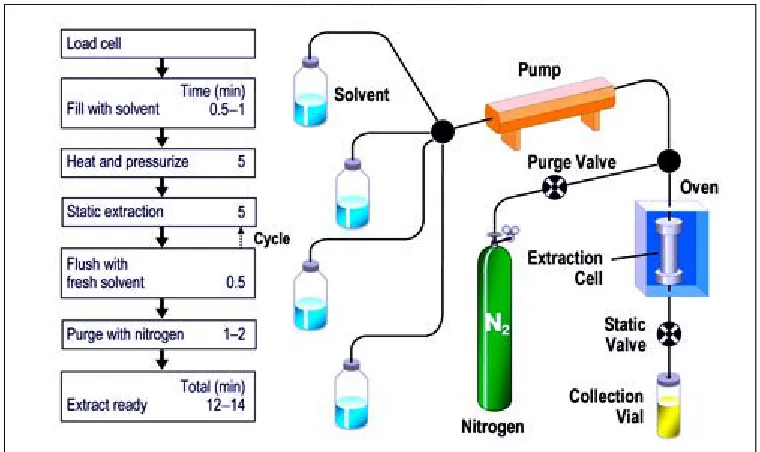
One of the oldest methods of solvent extraction is Soxhlet extraction, which is essentially a room temperature extraction that requires large amounts of solvent and several hours for completion. Since the development of Soxhlet extraction, other methods such as microwave extraction, automated Soxhlet extraction, sonication extraction and supercritical fluid extraction have been used to reduce the amount of time and solvent used.[52] Accelerated Solvent Extraction (ASE®) is one of the newest techniques that utilizes high pressures and temperatures to increase extraction efficacy. Figure 2.1 shows a schematic and procedure of the ASE® 200 system produced by Dionex.[53] In this system, a sample cell
29 refill the sample cell with fresh solvent if several extractions are desired for the same sample. It also has four different solvent reservoirs, which allow for mixing or switching of the
Figure 2.1 Accelerated Solvent Extractor (ASE®) 200 Schematic
30 2.5.2. Advantages
The automation of the ASE® makes the handling of many samples more efficient because less time is spent measuring solvent and preparing for extraction. The capacity for the ASE® system to reach high temperatures and pressures increases solubility effects, mass transfer, and disruption of surface equilibria, which makes the solvent extraction more efficient.[52] Richter et al. discusses the increased ability of a solvent to solubilize an analyte and faster diffusion rates with increasing temperature.[52] Compared to other extraction systems, the ASE® can have faster extraction times because its design allows for multiple cycles of fresh solvent to come in contact with the same material sample. The amount of solvent initially dispensed into the sample cell can be flushed into the collection tube and new solvent can be introduced. A larger concentration gradient is created between fresh solvent and the sample matrix.[52] This creates faster mass transfer of analyte in the material into the fresh solvent, and ultimately leads to faster extraction time.
31 interaction of a contaminant within the material matrix. The hydrogen bonding, dipole interactions, and van der Waals forces are disrupted and the activation energy needed for desorption of an analyte from the material matrix is reduced.[52] The high pressures reached in the ASE® allow for solvents to remain liquid even at temperatures above their boiling point. Higher temperatures cause solvents to have lower viscosity and reduces the surface tension of a solvent, contaminate and material sample.[52] This enables the solvent to have more penetration of a material matrix and faster dissolving of an analyte. Solvent extraction techniques that are done at atmospheric pressure do not have the benefit of forcing solvent in to the pores of a material. Richter et al. compares the effects of using high pressure in the ASE® system to high-pressure liquid chromatography.[52] The pressure in the sample cell forces the liquid to have more intimate contact throughout the material matrix for better extractions.
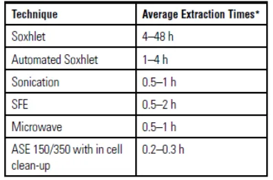
Tables 2.2 and 2.3 contain data comparing the time and amount of solvent used in several solvent extraction techniques.[55] There are some extraction techniques, such as microwave and supercritical fluid extraction, which have utilized the benefits of adjusting temperature and pressure for better extractions. However, the ASE® system offers more
32 Table 2.2 Extraction Times of Various Extraction Techniques
* “Extraction times are based on a per sample basis. This estimate does not include sample weighing, loading, or concentration, although it does include sample filtering, if necessary. In-cell clean-up is a technique used with ASE flow-through design, to add absorbent directly to the extraction cell that retains interferences. This technique further increases time savings.”[55]
Table 2.3 Solvent Usage of Various Extraction Techniques
* “Solvent usage are based on a per sample basis. Additionally,
ASE has many cells sizes to adapt to sample size requirements” ** “Solvent saver mode provides further reduction in
33 2.5.3. Considerations
Concerns for any extraction technique are carryover and cross-contamination. With systems that use high temperatures, there may be concern of thermal degradation. All of these issues were addressed with the ASE®.[56,57] The ASE® system eliminates cross-contamination by having low dead volume and automatic solvent rinses of the instrument can be programmed between samples.[56] The possibility of thermal decomposition was investigated using dichlorodiphenyltrichloroethane (DDT) because it will break down into dichlorodiphenyldichloroethylene (DDE) and dichlorodiphenyldichloroethane (DDD).[52,57] Endrin was also used because it breaks down in to endrin aldehyde and endrin ketone. Both DDT and endrin are known for their use as insecticides. Sand was spiked with the DDT and endrin, then the sand was extracted using ASE® at 150̊ C. Gas chromatography with an electron capture detector was used to analyze the extract. There was no DDE, DDD, endrin aldehyde, or endrin ketone in the extracts, which indicated that no thermal degradation could be detected.[52,57] However, it is always important to be aware of the properties of the target analyte and optimize the system conditions.
2.6Chromatography
2.6.1. Gas Chromatography
34 (CDC) are involved in protecting the public from exposure hazardous substances, and therefore have published gas chromatography methods for detecting these TICs.
A morpholine method has been developed for gas chromatography with a flame ionization detector (GC/FID). A MDN-1, nonpolar methylsilicone column, was used with a length of 30 m, inner diameter (i.d) of 0.32 mm and a stationary phase thickness (df) of 1.0 µm.[58] The injector and detector temperatures were set at 200̊ C and 250̊ C respectively. The oven temperature program consisted of ramping from 50̊ C to 110̊ C at 10̊ C per minute.[58] The column gas flow was set at 2.0 mL/min and the 1.0 µL injections were made with a 10:1 split ratio. Morpholine had a retention time of 4.45 min. and the total run time was 6 min.[58] The limit of quantitation of morpholine for this method was 45 ppb.
35 per minute. The column was a 30 m, 0.32 mm ID with 0.25 mm df Stabilwax DA fused silica capillary.[61] Sabilwax DA is a Crossbonded® acid-deactivated Carbowax® polyethylene glycol polar stationary phase manufactured by Restek. The carrier gas for this method was helium with a 1 mL/min flow rate.[61]
Acrylonitrile has been analyzed with a nitrogen phosphorus flame ionization detector (GC/NPD) with a limit of quantitation of 0.3 ppm.[62] A 6.1 m; 3.18 mm o.d stainless steel column was packed with 10% SP-100 on 80/100 Supelcoport, which is a mixture diatomaceous earth, silicon dioxide, quartz and free fatty acid. The injector and detector temperature were both set at 200̊ C, and the column was set at 100̊ C.[62] An additional method for acrylonitrile had the same injector and detector temperature settings but the column was set at 85̊ C.[63] This method was developed for GC/FID and used a 3 m, 3mm stainless steel column with 20% SP-1000 on 80/100 Chromosorb WHP. Chromosorb WHP is an acid washed, high performance combination of diatomaceous earth, silicon dioxide and quartz.
36 125̊ C to 275̊ C at a rate of 4.0̊ C per minute. The retention time using this column was 23.75 minutes.[66]
Acrolein has been analyzed using gas chromatography with a GC/NPD.[67] The column for this method is a 1.83 m, 6.35 mm o.d glass column packed with 10% UCON 50-HB-5100 and 2% KOH on 80/100 Chromasorb W-AW. UCON 50-50-HB-5100 is a polyalkylene glycol monobutyl ether polymer and Chromosorb W-AW has been acid washed. The injector and detector temperatures were set at 180̊ C and 275̊ C respectively. The carrier gas used was helium at a flow rate of 30 mL/min. The temperature program for the column consisted of a ramp from 100̊ C to 140̊ C at 4̊ C per minute and then a second ramp from 140̊ C to 180̊ C at 20̊ C per minute.[67] The column was held at 180̊ C for the remainder of the 25-min. run period. This method used 0.8-µL injections and had a limit of quantitation of 2.7 ppb.[67] Another method developed using GC/NPD had a 2-m; 2-mm glass column with 5% SP-2401-DB on Supelcoport (100-120 mesh).[68] SP-2401-DB indicates that part of the stationary phase has been deactivated for basic compounds and is meant for separating alkaloids. Helium was the carrier gas used at a flow rate of 30 mL/min. The injector temperature was set at 230̊ C, while the detector was set at 250̊ C. The column temperature profile included holding at 90̊ C for 8 min, then ramping at 20̊ C per minute to 200̊ C and holding for 11 min.[68]
2.6.2. Thermal Desorption
37 decontamination. However, traditional solvent extraction techniques can involve handling of the extract solution during preparatory procedures before chromatography, such as rotary evaporation or dilution. This handling could cause inaccurate measurements of volatile TICs.[69] Therefore, the volatile TICs, acrolein and acrylonitrile, were analyzed using thermal desorption-gas chromatography-flame ionization detection (TD-GC-FID). In this technique, material samples are placed in stainless steel tubes and heated to volatilize the analyte.[70] Then inert gas moves through the tube and carries the thermally desorbed chemical to a cold trap where it is collected before being volatilized again and sent to gas chromatography column. The collection of the analyte on the cold trap before injection into the GC keeps the injection band small, this process is known as refocusing.[70]
One disadvantage of this preparation technique is the sample size limitations from the thermal desorption (TD) tubes.[70] A material sample is cut into smaller samples for TD. Then the amount of analyte detected by the GC/FID will have to be extrapolated to determine the amount in the total exposed area. Although there is no human handling of an extraction solution, there is still a complicated two-step heating process. The heating, cooling, heat transfer lines, and high flow rate can all lead to analyte loss.[70]
Chapter 3. Experimental
3.1Experimental Approach
38 3.2Chemicals and Instrumentation
3.2.1. Chemicals
The chemicals used in this study included morpholine, acrylonitrile, m-cresol (all 99%), and 0.1N NaOH that were purchased from Acros Chemicals. Acetone, isopropanol (99%), sulfuric acid (37N), calcium hypochlorite (granular certified), dried potassium hydrogen phthalate (ACS grade) were purchased from Fisher Scientific. Acrolein (90%) was purchased from Aldrich Chemicals. Tide original scent high efficiency powder detergent was purchased at a local retailer. Methyl 4EC Insecticide with 4 pounds of methyl parathion per gallon was purchased from Cheminova.
3.2.2. Extraction and Analytical Instruments
39 Volatile chemicals, acrolein and acrylonitrile, were extracted using a Markes International Thermal Desorption (TD) Autosampler Series 2 Ultra. The sample tubes in TD were stainless steel SafelokTM tubes pack with glass beads (0.5-mm) and glass wool. Software for the TD was Unity version 4.1.15. The TD was connected to a Markes International Series 2 Unity2 Coldtrap packed with Tenax TA. The coldtrap was connected to an Agilent 7890A GC/FID. Separation was achieved with an Rtx-1 (30 m, 0.25 mm ID,1 um) column from Restek. The software used for processing was GC ChemSation 09'. The inorganic sulfuric acid was extracted using materials in AATCC Test Method 81.[71] A Mettler Toledo DL58 Titrator with DG111-SC electrode was used for analysis. The titration required 10-mL pipettes and 100-mL titration cups.
3.3Procedures
3.3.1. Modified ISO 6530 Splash Test Screening
40 The pump and syringe should be capable of delivering 60 cm3 (+ 1 cm3) in 60 sec (+ 1 sec). The viscosity of the challenge chemical can affect the flow rate delivered by the pump. To make sure that the pump delivered the correct amount of liquid in the specified time, the pump was calibrated. Calibrating the pump first required multiplying 60 mL by the density of the challenge chemical to determine how much the chemical volume should weigh. An empty polypropylene container was weighed and tared on the balance. A syringe with needle was filled with the challenge chemical and placed on the pump. The container was placed under the syringe needle. The needle was bent to deliver the chemical in a downward stream. The needle and syringe are pictured in Figures 3.1 and 3.2. The pump
Figure 3.1 Bent Non-Sterile Syringe Needle
Figure 3.2 Needle Attached to Syringe
41 volume delivery on the pump was adjusted. Once the correct weight was delivered, it was repeated five times.
A test specimen (6.35 cm by 30.48 cm) was cut and placed in a labeled polypropylene container. A larger sample size that covers the whole gutter could be used, but the sample size used in this procedure was reduced because of the limited amount of material. Another empty container was labeled for receiving the challenge chemical. A third container was labeled and held an absorbent wipe. All three containers were weighed with lids to the nearest 0.01 g. To begin the test, 2.54 cm of one end of the material specimen was folded under. Then the fold was held in position as the specimen was placed onto the gutter, with the folded end farthest from the pump. Folding the bottom of the sample kept any TIC from being absorbed by the edge of the material. The material was attached to the gutter with two clips on both sides, as pictured in Figure 3.3. The top edge of the sample was mounted 25.4 mm from the top of the gutter. Along with clips, a piece of 49 mm x 63.5 mm double sided tape was placed on the back of material samples that did not conform to the shape of the gutter. If tape was used, this was accounted for in the weight of the sample.
The labeled empty container was placed under the edge of the gutter to collect the test liquid running off the specimen. The syringe was loaded onto the pump so that the tip of the needle was 100 mm (± 2 mm) from the inclined surface of the gutter. The needle was aligned so that the liquid started to contact the top, center of the sample surface. Figure 3.4 shows the setup of the test apparatus. The cover of the gutter was placed on top of the test specimen, and then the pump was started. Once the liquid finished dripping into the
42 Figure 3.3 Attachment of Material to Gutter with Clips
43 nearest to the syringe, the absorbent wipe was used to wipe the entire length of the sample. The wipe was placed back in the appropriate labeled container with a lid. Next, the specimen was removed and placed in the appropriate container with a lid. The three containers with the liquid, wipe and material were weighed to the nearest 0.01g. After the test, the gutter was wiped and rinsed with the proper cleaning solvent to remove any residual chemical.
3.3.2. One-Day Field Simulation
Note that it was recommended that one day of training should have three exposures and three decontaminations of protective gear. The first two exposures simulate the material being splashed with the challenge chemical. The final exposure simulates an incident including pressure of the TIC against the material surface in ASTM F 903-03 cell.
3.3.2.1. First Exposure
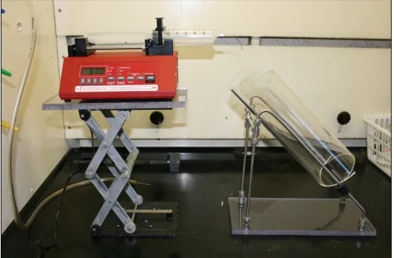
44
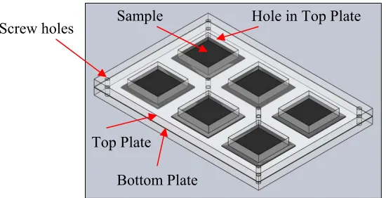
Figure 3.5 New Lab-scale Splash Simulation Device
GoreTM Joint Sealant tape (3/16 inch x 30 inch) was placed around the edges of each square hole on the sample side of the top plate. A 48.8-cm2 sample was cut and weighed. A small a piece of double-sided tape was put on the back center of the sample. The sample was placed on the bottom plate of the splash device. Then the top part of the splash device, GoreTM tape side down on the sample, was screwed to the bottom plate. A pipette was used to place 1 mL of the challenge chemical in the center of the material and it was allowed to sit on the sample for 3 min. Then the surface liquid was wiped off with a lint free absorbent wipe. The sample was removed and weighed. The tape was left behind on the plate. It was determined that the small amount of fibers left on the tape was negligible. After exposure, the sample was ready for the first decontamination procedure.
3.3.2.2. First Decontamination
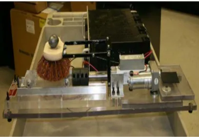
A mechanical scrubbing decontamination device was developed for this project, and it is pictured in Figure 3.6. This device used a linear actuator to scrub a material sample back
Sample Screw holes
Bottom Plate Top Plate
45 and forth horizontally. Several scrubbing heads such as different brushes and sponges were used in the development of the decontamination procedure. The scrubbing head Figure 3.6 was the rough bristle brush. However, ultimately this head was replaced with a soft sponge pictured in Figure 3.7. The reasons for this choice are discussed in Appendix A.1 of this paper.
46 Figure 3.6 Decontamination Device
Figure 3.7 Sponge That Attaches to Decontamination Device
47 minutes to determine the number of scrubs typical per boot. A scrub was one forward and back motion. The number of scrubs for the total area of the boot was used to calculate the number of scrubs that a 48.8 cm2 sample would encounter. The actuator was set to scrub the whole length of the sample.
3.3.2.3. Second Exposure and Decontamination
After drying for one hour following the first exposure and decontamination, the same material was exposed to a second exposure and decontamination with the same procedures discussed in sections 3.3.2.1 and 3.3.2.2.
3.3.2.4. Third Exposure and Decontamination
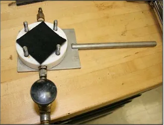
After the second hour drying following exposure and decontamination, the final exposure of the material sample used a modified ASTM F 903- 03 procedure for a simulation of a high level exposure to TICs involving impact pressure.[38]
48 Figure 3.8 Disc Placement in the Restraining Ring of Penetration Cell
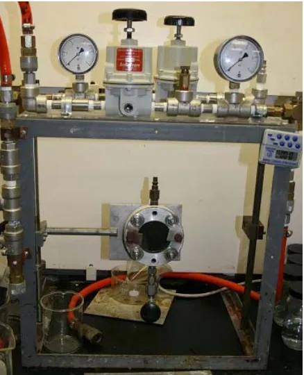
The weight of the samples was also recorded to the nearest 0.001g. The specimen was loaded “in the test cell with the normally outside surface toward the chemical chamber”, shown in Figure 3.9.[38] Then the sample was secured in place by placing the restraining ring on the back side of the sample and bolting the pieces of the cell together, as pictured in Figure 3.10. The cell was loaded into the testing apparatus shown in Figure 3.11, so that the material sample was vertical. This test was done at ambient temperature and a timer was
49 Figure 3.10 Assembled Penetration Cell
Figure 3.11 Penetration Test Apparatus
50 was released and the chemical remained in contact with the material surface at ambient pressure for the additional 2 minutes. After the elapsed time, a collection container was set under the cell and the liquid was drained. After draining, the material sample was removed
Figure 3.12 Syringe Used to Deliver Challenge Chemical To Penetration Cell
from the cell and the surface chemical was wiped away with a lint free absorbent wipe. The test specimen was observed for any discoloration or indications of liquid penetration. If liquid penetrated the material at any point during the three minute test period, then the material failed and no further testing was carried out on that sample. Material samples that passed were weighed and placed in an air tight container. The test cell was flushed with proper solvent to clean it for the next exposure.
51 3.3.3. Four-Day Field Simulation
The four-day exposure used similar procedures to the ones used in the one-day field exposure except the ASTM F 903 cell exposure was not done until the last exposure of the last day. It was determined by the project panel that this was an extreme exposure scenario that should only be done once during the simulation.
The first day of exposure began with the exposure procedure in section 3.3.2.1 followed by the decontamination procedure in section 3.3.2.2. This exposure and decontamination procedure was repeated two additional times for the first day. The same procedure for the first day was repeated for the second and third days. At the end of each day the sample was allowed to dry for at least four hours. Then, if the material had a surface finish, for example a fluorocarbon coating, the finish was restored and allowed to dry for at least twelve additional hours before starting the next simulated day.
The final (fourth) day of simulation first consisted of two exposures using the procedure in section 3.3.2.1 with decontaminations following each exposure and using the procedure in section 3.3.2.2. The final exposure followed the procedure using the ASTM F 903 cell in section 3.3.2.4 and then the sample was decontaminated again with the procedure in section 3.3.2.2. Once the sample had dried for at least four hours, it was extracted and analyzed with the appropriate method.
3.3.4. Wipe Test
52 and wiped across a sample that had completed the four-day simulation procedure. After wiping in one direction then the sample was rotated 90̊ and wiped again. Then the wipe was extracted and analyzed with the same procedure as the material sample.
3.3.5. Extraction Methods 3.3.5.1. Semi-Volatile TICs
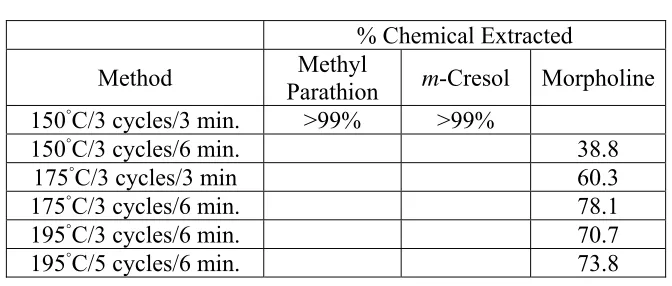
The ASE was used to extract the semi-volatile TICs, including m-cresol, methyl parathion, and morpholine from the material sample. The rubber solid control samples used in this study were from a CBRN boot that was currently certified for chemical resistance and assumed to retain very little chemical. Therefore, a leather material was used to determine the extraction method. The goal of the extraction was to recover any TIC left inside the material. For the ASEmethod development, a 25.9 cm2 material sample was weighed. Six drops of one TIC were placed in the center of the sample and allowed to sit for three minutes. When the time was complete, the surface chemical was wiped with a lint free absorbent wipe and the material was weighed again. The samples were loaded into the extractor stainless steel cells containing a paper filter in the bottom. Glass beads were poured into the cells to fill empty space.
53 detected by GC/FID (the methods are discussed in section 3.3.6) after extraction was compared to the amount of chemical absorbed by the material gravimetrically to calculate the percent chemical extracted. Table 3.1 shows that methyl parathion and m-cresol were recovered well at 150◦C with three cycles of fresh solvent and three minute static time at each cycle. The morpholine was harder to remove from the leather samples. The tanning process in leather can leave the material acidic and morpholine has been used to treat leather.[26,27] Morpholine is basic and the reactions in the leather could be the reason why not all of the morpholine was recovered.
Table 3.1ASE Method Development with Leather % Chemical Extracted
Method Parathion Methyl m-Cresol Morpholine 150◦C/3 cycles/3 min. >99% >99%
150◦C/3 cycles/6 min. 38.8
175◦C/3 cycles/3 min 60.3
175◦C/3 cycles/6 min. 78.1
195◦C/3 cycles/6 min. 70.7
195◦C/5 cycles/6 min. 73.8
54 Increasing the extraction temperature for the methyl parathion and m-cresol only insured that >99% of the chemical was being extracted.
In the final method for the ASE, the total exposed area (25.9 cm2) was cut from the center of the material sample. Next, the cut piece was rolled and placed in to a 22-mL ASE sample cell, with a paper filter and glass beads. The oven temperature was set to 175◦C. There was no preheating of the samples in the ASE. The program for one extraction of a sample first involved filling 25% of the cell volume with isopropanol (IPA) and holding at 1500 psi for 6 min. Then the IPA was released into the collection vial and the cell was filled again with fresh IPA for an additional 6 minutes. This process was repeated for a third cycle, then a final purge of the cell was set for 60 sec. Then two more extractions, each involving three total cycles of fresh solvent and holding at 6 min per cycle, were done with the same sample. Therefore, the sample was exposed to a total of 9 increments of fresh solvent.
3.3.5.2. Volatile TICs
The volatile TICs, acrolein and acrylonitrile were removed from the material by thermal desorption. The thermal desorption system was connected to the gas chromatograph. The method for the thermal desorption is included in the gas chromatography method for acrolein and acrylonitrile in section 3.3.6.2.
3.3.5.3. Inorganic TIC
55 placed in 250mL of boiling water for 10 minutes. Then the material sample was removed from the extract.
3.3.6. Analytical Techniques
3.3.6.1. GC/FID for Semi-Volatile TICs
56 Table 3.2 shows the calibration results for m-cresol, methyl parathion, and morpholine TICs. Table 3.2 also notes the average retention time for each chemical. m-Cresol and methyl parathion were calibrated using solutions ranging from 3 ppm to 3000 ppm in IPA. Morpholine was calibrated from 30 ppm to 3000 ppm in IPA. The limit of detection (LOD) “is the smallest quantity of analyte that is “significantly different” from the blank”[72] The standard deviation is calculated from the mean signal of replicates of a sample and measures random variation (noise). The limit of quantitation (LOQ) “is the smallest amount of analyte that can be measured with reasonable accuracy”.[72] An example calculation of the LOD and LOQ for m-cresol is below:
LOD = 3s/m where, s = standard deviation of a low concentration sample m = slope of the calibration curve
LOD = [3(464 area counts)]/2263 area counts/concentration (ng/μL) = 0.6 ng/μL LOQ = 10s/m
LOQ = [10(464 area counts)]/2263 area counts/concentration (ng/μL) = 2.1 ng/μL
Table 3.2 GC/FID Calibration Results for Semi-Volatile TICs
TIC m-Cresol Methyl
Parathion Morpholine
Retention Time 5.429 10.358 4.232
R2 0.9999 0.9999 0.9999
Slope 2263 429 1415
Standard Deviation of Low
Concentration Sample 464 81 533
Limit of Detection
(ng/μL) 0.6 0.6 1.1
Limit of Quantitation
57 3.3.6.2. TD/GC/FID for Volatile TICs
The same TD and GC oven method was used for both acrolein and acrylonitrile. All of the tubes were placed in the TD instrument and desorbed at 200oC for 12.5 min. using helium carrier gas with a flow of 20 mL/min. The desorbed chemicals were sent to the cold trap. The cold trap was heated to 300oC at 20oC/sec then held for 3 min. to volatize the trapped materials and transport them to the GC column. Before entering the GC column the acrylonitrile volatized sample was split 2:1. The acrolein sample was run in splitless mode. The oven was programmed at 35◦C, held for 1 min., ramped to 55◦C at 10◦C/min., held for 2 min, ramped to 80◦C at 2◦C/min., held for 1 min., ramped to 130◦C at 20◦C/min.
Each TD tube was loaded with glass wool, glass beads, and a sample strip. The strips for the rubber control were each 2.3 cm2 and the strips for the leather were each 1.8 cm2. Then the tubes were capped and placed in the instrument. The ng desorbed from three strips was averaged and proportioned to find the mg of TIC in the total exposed area.
58 Table 3.3GC/FID Calibration Results for Volatile TICs
TIC Acrolein Acrylonitrile
Retention Time 4.34 3.87
R2 0.9997 0.9959
Slope 0.3 6.4
Standard Deviation of Low
Concentration Sample 0.27 1239
Limit of Detection
(ng/μL) 3 581
Limit of Quantitation
(ng/μL) 9 1936
3.3.6.3. Titration for Sulfuric Acid
The residual acid in these samples was extracted using AATCC test method 81-2006.[71] The liquid extracted from the samples was titrated with 0.01N NaOH using the Mettler Toledo DL58 automated titrator. The 0.01N NaOH solution was standardized using KHP to get a more accurate solution normality. Sample extract (10mL) was transferred into a titration cup and DI water was used to bring the solution to 50mL. Each extraction was titrated three times and the results were averaged. The uncertainty of the titrations was calculated by repeating the titration of a solution 13 times and calculating the standard deviation, which was 0.02 mL of consumed NaOH.
59 control samples was subtracted from the mg of acid found in actual exposed samples. This gave a better indication of how much acidity is added to the material by the TIC.
Table 3.4 Titration Results for Acid in Unexposed Samples
Scenario (mg acid) Rubber Leather C (mg acid)
No Decontamination 0.14 0.67
One Decontamination 0.12 0.47
Three Decontaminations
-One-Day Simulation 1.25 3.89
Twelve Decontaminations –
Four-Day Simulation 0.00 4.35
Chapter 4. Results and Discussion
4.1 Splash Test