University of Windsor University of Windsor
Scholarship at UWindsor
Scholarship at UWindsor
Electronic Theses and Dissertations Theses, Dissertations, and Major Papers
2013
Plasma Electrolytic Oxidation (PEO) Coatings on an A356 Alloy for
Plasma Electrolytic Oxidation (PEO) Coatings on an A356 Alloy for
Improved Corrosion and Wear Resistance
Improved Corrosion and Wear Resistance
Zhijing Peng
University of Windsor
Follow this and additional works at: https://scholar.uwindsor.ca/etd
Recommended Citation Recommended Citation
Peng, Zhijing, "Plasma Electrolytic Oxidation (PEO) Coatings on an A356 Alloy for Improved Corrosion and Wear Resistance" (2013). Electronic Theses and Dissertations. 4764.
https://scholar.uwindsor.ca/etd/4764
This online database contains the full-text of PhD dissertations and Masters’ theses of University of Windsor students from 1954 forward. These documents are made available for personal study and research purposes only, in accordance with the Canadian Copyright Act and the Creative Commons license—CC BY-NC-ND (Attribution, Non-Commercial, No Derivative Works). Under this license, works must always be attributed to the copyright holder (original author), cannot be used for any commercial purposes, and may not be altered. Any other use would require the permission of the copyright holder. Students may inquire about withdrawing their dissertation and/or thesis from this database. For additional inquiries, please contact the repository administrator via email
Plasma Electrolytic Oxidation (PEO) Coatings on
an A356 Alloy for Improved Corrosion and Wear
Resistance
by
Zhijing Peng
Thesis
Submitted to the Faculty of Graduate
Studies through Engineering Materials
in Partial Fulfillment of the
Requirements for the Degree of Master
of Applied Science at the University of
Windsor
Windsor, Ontario, Canada
2013
Plasma Electrolytic Oxidation (PEO) Coatings on an A356 Alloy For Improved Corrosion and Wear Resistance
by
Zhijing Peng
APPROVED BY:
Dr. H. Wu
Department of Electrical and Computer Engineering
Dr. H. Hu
Department of Mechanical, Automotive and Materials Engineering
Dr. X. Nie, Advisor
Department of Mechanical, Automotive and Materials Engineering
Dr. V. Stoilov, Chair of Defense
Department of Mechanical, Automotive and Materials Engineering
III
DECLARATION OF CO-AUTHORSHIP/PREVIOUS PUBLICATION
I. CO- AUTHORSHIP DECLARATION
I hereby declare that this thesis incorporates material that is result of joint research, as follows:
This thesis incorporates the outcome in collaboration with Dr. Yin Chen for SEM pictures and
samples preparation under the supervision of Professors Xueyuan Nie. The collaboration is
covered in Chapter 4 of the thesis. This thesis also incorporates the outcome in collaboration
with Dr. Tse Cheng for roughness measurement under the supervision of Professors Xueyuan
Nie. The collaboration is covered in Chapter 6 of the thesis. In all cases, the key ideas, primary
contributions, experimental designs, data analysis and interpretation, were performed by the
author, and the contribution of the co-author was primarily through the provision of
experiments.
I am aware of the University of Windsor Senate Policy on Authorship and I certify that I have
properly acknowledged the contribution of other researchers to my thesis, and have obtained
written permission from each of the co-author(s) to include the above material(s) in my thesis.
I certify that, with the above qualification, this thesis, and the research to which it refers, is the
IV
II. DECLARATION OF PREVIOUS PUBLICATION
This thesis includes 4 original papers that have been previously published/submitted for
publication in peer reviewed journals/conference proceedings, as follows:
Thesis
Chapter Publication title/full citation
Publication status
Chapter4 Zhijing Peng, Ying Chen and Xueyuan Nie, Corrosion properties of plasma electrolytic oxidation ceramic coatings on an A356 alloy tested in an ethanol-gasoline fuel (E85) medium. Advanced Materials Research, Vols. 282-283 (2011) pp 774-778
Published
Chapter 5 Z. Peng and X. Nie, Galvanic corrosion property of contacts
between carbon fiber cloth materials and typical metal alloys in an aggressive environment.
Surface & Coatings Technology, 215 (2013) 85-89
Published
Chapter 6 Zhijing Peng, Tse Cheng and Xueyuan Nie, MoS2/Al2O3 composite coatings on A356 alloy for friction reduction.
Advanced Materials Research, Vol. 496 (2012) pp 488-492
Published
Chapter 7 Zhijing Peng and Xueyuan Nie, Effect of plasma electrolytic
oxidation coatings on friction and wear behavior of aluminum engine cylinder bores.
Surface & Coatings Technology, to be submitted
Proceed
I hereby certify that I have obtained a written permission from the copyright owner(s) to
include the above published material(s) in my dissertation. I certify that the above material
describes work completed during my registration as graduate student at the University of
Windsor.
I declare that, to the best of my knowledge, my thesis does not infringe upon anyone’s
copyright nor violate any proprietary rights and that any ideas, techniques, quotations, or
V
otherwise, are fully acknowledged in accordance with the standard referencing practices.
Furthermore, to the extent that I have included copyrighted material that surpasses the bounds
of fair dealing within the meaning of the Canada Copyright Act, I certify that I have obtained a
written permission from the copyright owner(s) to include such material(s) in my dissertation.
I declare that this is a true copy of my thesis, including any final revisions, as approved by
my dissertation committee and the Graduate Studies office, and that this thesis has not been
VI
ABSTRACT
Plasma electrolytic oxidizing (PEO) is an advanced technique that has been used to deposit
thick and hard ceramic coatings on aluminium (Al) alloys. This work was however to use the
PEO process to produce thin ceramic oxide coatings on an A356 Al alloy for improving
corrosion and wear resistance of the alloy. Effects of current density and treatment time on
surface morphologies and thickness of the PEO coatings were investigated. The improvement
of galvanic corrosion properties of the coated A356 alloy vs. steel and carbon fibre were
evaluated in E85 fuel or NaCl environments. Tribological properties of the coatings were
studied with comparison to the uncoated A356 substrate and other commercially-used engine
bore materials. The research results indicated that the PEO coatings could have excellent
VII
DEDICATION
I would like to dedicate this dissertation to my parents for their unconditional love, support and
encouragement.
I also would like to thank my wife. Her love and support enable me to go through the difficult
time and finally complete this thesis.
VIII
ACKNOWLEDGEMENTS
This study could not have done forward without the financial support from the
Natural Sciences and Engineering Research Council of Canada (NSERC).
I would like to thank my thesis advisor, Dr. Xueyuan Nie, for his valuable suggestions and
excellent supervision of this research work during my study.
Many thanks to my committee members (Dr. Henry Hu, Dr. Huapeng Wu) for their helpful
comments and careful review of this work.
I would like to thank Mr. Junfeng Su, Mrs. Ying Chen, Mr. Rayid Hussin and Dr. Tse Cheng
from University of Windsor for their assistance with the experiments.
Finally, I am thankful to the faculty, staff and graduate students at the Department of
Mechanical, Automotive and Materials Engineering of the University of Windsor, particularly
IX
TABLE OF CONTENTS
DECLARATION OF CO -AUTHORSHIP/PREVIOUS PUBLICATION... III
ABSTRACT... .. VI
DEDICATION... ...VII
ACKNOWLEDGEMENTS...VIII
L I S T O F T A B L E S ...X I
LIST OF FIGURES……… XII
CHAPTER 1 INTRODUCTION ... 1
REFERENCES... ... .9
CHAPTER 2 LITERATURE REVIEW... ………...………12
1. The PEO equipment ... ... ...13
2. Deposition procedure... …….. 14
3. PEO coating structure... 16
4. Tribological properties of PEO coatings... .17
5. General corrosion characteristics of Al alloys……….20
6. Summary of literature review……….23
REFERENCES... ...24
CHAPTER 3 EXPERIMENTAL PROCEDURES... 28
1. Pin-on-disc/reciprocating tribology test…...28
2. Potentiodynamic polarization testing... .29
3. Zero Resistance Ammetry... 32
REFERENCES... …...33
CHAPTER 4 CORROSION PROPERTIES OF PLASMA ELECTROLYTIC OXIDATION CERAMIC COATINGS ON AN A356 ALLOY TESTED IN AN ETHANOL-GASOLINE FUEL (E85) MEDIUM……….34
1. Introduction... 34
2. Experiments... 35
3. Results... ……….36
4. Conclusion ... ………..40
X
CHAPTER 5 GALVANIC CORROSION PROPERTY OF CONTACTS BETWEEN CARBON FIBER CLOTH MATERIALS AND TYPICAL METAL ALLOYS IN AN
AGGRESSIVE ENVIRONMENT... 43
1. Introduction...43
2. Experimental details... …………45
3. Results and discussion ... 47
4. Conclusions... 55
REFERENCES... ... 56
CHAPTER 6 MOS2/AL2O3 COMPOSITE COATINGS ON A356 ALLOY FOR FRICTION REDUCTION...58
1. Introduction ... ………... 58
2. Experimental procedure... 59
3. Results and Discussion... 61
4. Conclusions... …….. 64
REFERENCES ... ……….65
CHAPTER 7 EFFECT OF PLASMA ELECTROLYTIC OXIDATION COATINGS ON FRICTION AND WEAR BEHAVIOR OF ALUMINUM ENGINE CYLINDER BORES……… ………66
1. Introduction... ...66
2. Experiment method... ………….68
3. Result and Discussion...70
4. Conclusions ... ...83
REFERENCES ... 84
CHAPTER 8 SUMMARY AND FUTURE WORKS………... ……87
1. Summary... ……….87
2. Future work……….90
APPENDIX COPYRIGHT RELEASES FROM PUBLICATIONS... …. …91
XI
LIST OF TABLES
Table 4.1. Potentiodynamic polarization parameters of uncoated/coated A356 and steel in E85... 37
XII
LIST OF FIGURES
Figure 2.1 Typical arrangement of the equipment used for PEO treatment………...14
Figure 2.2 Current-voltage diagram for the processes of plasma electrolysis: discharge phenomena are developed in the dielectric film on the electrode surface………... …...15
Figure 2.3 Illustrates the structure of the PEO coating………... 16
Figure 2.4 Segmented Ring/Bore Liner test rig………..19
Figure 2.5 Potentiodynamic polarization curves of untreated substrate materials and PEO alumina coatings in 0.5M NaCl solution after different immersion times………..22
Figure 3.1 Sliding tester attached on (a) Sciland Pin/Disc Tribometer PCD-300A, (b) load cell and cantilever beam, (c) sample holder for reciprocating mode and (d) sample holder plus load...28
Figure 3.2 Typical polarization curve………...30
Figure 3.3 Theoretical cathodic polarization scan………...31
Figure 3.4 Tafel slope calculation………31
Figure 3.5 (a) Schematic view of three-electrode cell and (b) Electrochemical corrosion polarization testing equipment, (c) General galvanic corrosion test and (d) ZRA test… ……...33
Figure 4.1 Cross sectional SEM micrographs of samples A-D coatings………...37
Figure 4.2 Potentiodynamic polarization corrosion curves of the samples in an E85 medium……….38
Figure 4.3 The galvanic corrosion current density of the test samples in the E85 medium ………...39
XIII
ZRA corrosion tests………..40
Figure 5.1 Optical images of (a) ASTM Al018 steel, (b) aluminum alloy A356 and (c)
Ti6Al4V alloys after corrosion tests. lnserts in (a), (b) and (c) showed the corroded areas at a
low magnification……….. 48
Figure 5.2 Potentiodynamic polarization corrosion curves of the samples in a 3.5% NaCl
solution. Treatment modes for samples: A- bipolar, B- unipolar/bipolar, C bipolar/unipolar,
D unipolar……...………..49
Figure 5.3 The galvanic corrosion current density curves of the test samples in the 3.5%
NaCl solution for (a) all samples and (b) samples A, B and D at a magnified scale. A -bipolar,
B-unipolar/bipolar, C-bipolar/unipolar, D-unipolar………...………52
Figure 5.4 SEM micrographs of (a. b) uncoated A356, (c) Sample B and (d) Sample C after
ZRA corrosion tests………53
Figure 5.5 The optical micrographs and galvanic corrosion current density of the test samples in
the 3.5% NaCl solution for Ti6Al4V alloys: (a) uncoated, (b) treated by a bipolar current mode
(TB) and (c) treated by a unipolar mode………54
Figure 6.1 C.O.F. curves of (a) A356, S1 and S2 and (b) S3, S4 and S5 at 2N & 50m dry test
conditions……….61
Figure 6.2 C.O.F. curves of (a) S1 and (b) S5 at 1N and 50m dry test conditions……….62
Figure 6.3 SEM micrographs and EDX spectra of coatings on (a, b) Sample 1 (without MoS2)
and (c. d) Sample 5 (with MoS2)………..63
Figure 6.4 (a) Wear rates of samples S1 and S2 under the pin-on-disc dry test conditions for both
2N and 1N (labeled with*) loads, and (b) tribological behaviours of A356 and coated samples
XIV
Figure 7.1 Optical micrographs of (i) the wear tracks on PEO coatings and (ii) wear scars on
counterface steel balls, and (iii) C.O.F. for (a) Coating S1, (b) Coating S2, and (c) Coating S3.
………72
Figure 7.2 Optical micrographs of (i) the wear tracks on reference samples and (ii) wear scars on
counterface steel balls, and (iii) C.O.F. for (a) PTWA coating, (b) Alusil, and (c) cast
iron…...75
Figure 7.3 SEM micrographs for (a, b) PWTA, (c-d) Alusil and (e-f) cast iron liner specimen
after the tribotest……….79
Figure 7.4 SEM micrographs and EDX spectra of the coating S2 after tested at a 15N, 1000m
and oil lubricant condition………..80
Figure 7.5 SEM micrographs and EDX spectra of the coating S1 after tested at a 15N, 1000m
and oil lubricant condition………... 81
Figure 7.6 Optical images of (a) the coating S1 and (b) counter-ball as well as (c) PTWA coating
1
CHAPTER 1
INTRODUCTION
Recently, environmental problems caused by fuel emissions and limited fuel supplies force
the automotive industry to use new lightweight materials. The need to improve fuel economy
and safety performance, reduce exhaust emissions and provide customers with new features have
caused new renovations in components design including reduced friction, weight, and higher
engine operating temperatures for improved efficiency. To achieve such an objective,
aluminium (Al) alloys are noted for their unique combination of desirable characteristics
including their high strength-to-weight-ratio, good castability, low thermal expansion and high
corrosion resistance. These properties have led to their increase sufficiently in the use of
automotive besides aircraft and aerospace industry. Aluminum-silicon (AlSi) alloys such as Al
356 [1] have been commercially used to produce engine blocks because of its high strength
over weight ratio. The engine block cylinder works under thermal and mechanical cyclic
stresses in relative motion with piston rings. It is shown that good wear resistance is a critical
property to engine block's working life. Although aluminum alloys are becoming increasingly
important, and more widely used in the automobile industry due to their excellent
properties, including high strength to weight ratio, good castability and machinability
their corrosion resistance is relatively poor because of the presence of non-corrosion resistant
elements and phases (Cu, Si, Mg, etc) and microstructural defects (such as pores) in these
alloys. Many industral approaches to improving corrosio resistance have been taken
including the development of new alloy systems, the use of inhibitors, and surface
2
A356 series cast aluminium-silicon alloys have been increasingly applied as lightweight
components especially using for all types of internal combustion engines as pistons, cylinder
blocks and cylinder heads. In this kind of alloys, silicon is added to aluminium and can be used
to form a second phase in order to improve wear resistance for tribological applications.
However, compared with steel and iron, aluminium alloys such as A356 are relatively soft and
have poor wear properties especially against scuffing wear under conditions of dry lubrication
such as those which exist during starting engines period. It is one of the failure mechanisms
affecting the useful life of engines. [3-5] Also the National Ethanol Vehicle Coalition (NEVC)
and the Petroleum Equipment Institute have pointed out that aluminum alloy is sensitive to
corrosion from ethanol. The use of corrosive ethanol such as E85 can be accommodated through
the use of appropriate coatings, valve seat materials, adhesives, and fuel additives [6].
Surface coating can be used to minimize the possibility of sever wear by lowing friction and
hardening the surface. Various coatings have been developed to improve wear properties of the
alloys. Titanium nitride and diamond-like carbon (DLC) coatings are deposited by vacuum
vapour deposition (PVD and CVD) methods which need high vacuum in vacuum chambers [7-8].
Electroplating and electroless plating-Nickel based ceramic composite coatings (NCC) have a
function to increase the wear resistance but could be corroded when sulphur-contained fuel is
used [9]. Thermal spraying technology can produce Fe-based or stainless steel-Ni-BN coatings.
However, thermal spraying only make mechanical adhesion of coatings to base materials, and
precise process control (including surface pre-treatment) is hard for good adhesion between
3
Al cylinder interior surfaces in terms of economical manufacturing process, reproducible and
reliable processing. Hard anodizing is an effective and equipment simple method used to produce
hard ceramic coatings on aluminium alloys. Since alloying elements such as copper and silicon
do not anodize during the process, leaving microscopic voids in the aluminum oxide coating, the
coating exhibits a low peeling resistance and high friction coefficient. In general case, hard
anodic coatings are not suitable to be used to high Si (containing >8% silicon) alloys. [11]
For corrosion application, several surface modification and coating techniques have been
developed to enhance the corrosion resistance of Al alloys. These techniques are sol-gel coatings
[12-13], ion implantation [13-15], conversion coatings [16], physical vapor deposition (PVD)
[l7-20] chemical vapor deposition (CVD), and thermal spraying [21]. However, most of these
methods involve high temperatures during processing (CVD, PVD and thermal spray) or
post-treatment (sol-gel), which may damage the coating and /or substrate [22]. In addition,
sol-gel processing has been of limited use due to poor interfacial adhesion, shrinkage and
oxidation of the substrate [23]. Conversion coatings are mainly based on chromium
compounds that exhibit good corrosion resistance, but have also been reported to be highly
toxic and carcinogenic [23]. Ion implantation has found limited success in increasing the
pitting potential of coatings.
Plasma electrolytic oxidation (PEO) is a relatively new plasma-assisted electrochemical
treatment which is considered as a cost-effective and environmentally friendly surface
engineering technique and can be broadly applied to metal surface cleaning, metal-coating [24],
4
A PEO process in a silicate solution can produce Al-Si-O ceramic coatings with a high adhesion,
hardness, and thickness on Al-based materials. Also, the PEO process combining with other
processes such as CVD [30] and electrophoretic deposition (EPD) [31] can be used in producing
super hard, low friction, and biomedical compatible coatings.
Several studies have been involved in the coating formation mechanisms [32-34], characteristics
of the coating deposition including tribological properties [27-29] of the ceramic oxide coatings
deposited using PEO on various Al alloy substrates. However, most of those works focused on
2xxx and 6xxx series, i.e., low silicon (<1.5% Si) content Al alloys, and characterized thick
oxide coating (i.e., >100 m in thickness). Little studies focus on the initial stage of the PEO
coating formation and properties of the thin PEO coatings (i.e.,< 50 m ). Due to the rapid
growth in applications of high silicon cast Al-Si alloys, the applications of the PEO on the cast
Al-Si alloys have been paid more attention since recently [35, 36]. However, to our knowledge, a
detailed investigation of the effects of silicon content in Al-Si alloys such as A356 alloy on the
PEO coating formation and morphology has not been conducted yet.
The global fuel crises in the 1970s triggered awareness in many countries of their vulnerability
to oil embargoes and shortages. Considerable attention was focused on the development of
alternative fuel sources, in particular, the alcohols [37]. Because it is a renewable bio-based
resource and is oxygenated, ethyl alcohol is considered an attractive alternative fuel to reduce
both the consumption of crude oil and environmental pollution. If ethanol from biomass is
5
same car using reformulated gasoline [38]. Currently, ethanol is blended with gasoline to
form an E10 blend (10% ethanol and 90% gasoline by volume), but it can be used in
higher concentrations s u c h as E85 or E95. In the past few years, automotive manufacturers
have developed flexible fuel vehicles (FFVs) that can run on E85 fuel or any other
combination of ethanol and gasoline [6].
Carbon fibers which will be used as commercial vehicle’s bodies in the future years and
aluminum alloys which can be used as chassis on future vehicles have created considerable
interest as structural engineering materials and in many applications carbon fiber composite
materials are connected to aluminum metals. When carbon fibers in a polymer based matrix
composite are used as a structural component, it should be noted that carbon fiber is a very
efficient cathode and very noble in the galvanic series. Therefore, contact between carbon fiber
composites and metals in an electrolyte such as rain or seawater will be extremely undesirable if
the metal is highly active and low in the galvanic series. If galvanic coupling occurs, galvanic
corrosion of the metal may occur. Additional possibilities of corrosion related to raising the
galvanic potential, particularly for passive metals such as aluminum alloys include: initiation of
pitting corrosion and extensive crevice corrosion. [39, 40]
Thus, in this thesis, low voltages (<500V) were adopted to produce thin PEO coating with
thickness less than 50 um. The PEO process on aluminium alloys A356 (~7%Si) was
investigated in terms of electrical and electrolytic parameters on formation, morphology,
composition of the PEO coatings. Potentiodynamic polarization and Zero Resistance Ammetry
6
uncoated Al alloys (A356) in an alternative fuel. Effects of the current modes on the coating
morphologies and anti-corrosion performance were particularly discussed in one of the chapters
in this thesis. Also, the galvanic corrosion between metals and a carbon fiber sheet were
investigated. In order to investigate the possibility and intensity of galvanic corrosion, not only
potentiodynamic polarization but also zero resistance ammeter (ZRA) testing methods were used
to evaluate the corrosion properties of a steel and a titanium alloy as well as coated and uncoated
Al alloys (A356) in 3.5% NaCl solutions. As a result of this study, a better understanding of the
galvanic corrosion behavior of the carbon fiber-metal system can be achieved.
For improved friction and anti-wear properties, PEO coatings plus MoS2 particles has been
applied to the A356 alumina alloy through the electrophoretic deposition of MoS2 particles. The
alkaline electrolyte solution containing suspension of MoS2 particles was used to prepare a
composite film of MoS2 and Al2O3. The resulting microstructural and tribological properties
were examined via optical microscopy, scanning electron microscopy (SEM) and tribotests. A
reciprocating sliding tribometer was used to investigate the tribological and wear behavior of the
PEO coatings and counterface materials, compared with plasma transferred wire arc coating,
7
Objective and contents of this study
The objectives of this study were to:
1. Develop plasma electrolytic oxidation (PEO) coatings on an A356 aluminium alloy for its
corrosion and wear prevention.
2. Investigate the possibility and intensity of galvanic corrosion of coated and uncoated Al alloys
A356 vs. steel valve seats in E85 fuels and 3.5% NaCl solutions; investigate the galvanic
corrosion behavior of the carbon fiber against coated A356 compared to uncoated A356, steel
and Ti alloy; study the effects of the current modes on the coating morphologies and
anticorrosion performance.
3. Optimize the PEO process for improved friction and anti-wear properties; investigate the
tribological and wear behavior of the PEO coatings and counterface materials, compared with
plasma transferred wire arc coating, Alusil@ and casting iron samples, under dry and lubricated conditions.
Organization of the thesis
This thesis contains eight chapters. Chapter 1 gives introductory information on the usage of
A356 aluminium alloy in automotive applications and the need for improved corrosion and wear
resistance. Following this introduction, the relevant literatures regarding PEO coating technology
on Al alloys and previous research on the PEO coating formation and properties are reviewed in
Chapter 2. Chapter 3 describes the experimental instruments and procedures. Chapter 4 reports
investigation results of corrosion property of plasma electrolytic oxidation coatings tested in an
ethanol gasoline fuel (E85) medium. Chapter 5 presents the results and discussion of the
8
and without PEO coatings. In chapter 6, a new Al2O3/MoS2 composite coating was developed,
and its tribological properties were investigated under dry and lube conditions. Chapter 7
presents wear and friction properties of the PEO coating on engine bores, compared with
commercial engine block materials. Chapter 8 is to summarize the research results of this thesis
9
References
[1] A.M. Sherman, in E.A. Starke, Jr., T.H. Sanders, Jr., W.A. Cassada (ed.), Aluminium alloys:
their physical and mechanical properties, Vol. 331-337, Part 1, Trans tech publications Ltd.,
2000, p3-4.
[2] Y. Sun, Materials Letters 58 (2004) 2635- 2639
[3] R Shivanath, P.K. Sengupta, Eyre T S, The British Foundryman, 70 (1977), 349-356.
[4] A.S. Reddy, B.N.P Bai, K.S.S. Murthy, S.K. Biswas, Wear, 171 (1994), 115-127.
[5] B.S. Shabel, D.A. Granger, W.G. Truckner, in D. Olson Hardbound (ed.), ASM Handbook,
Vol. 18, 1992, p785-794.
[6] Handbook for Handling, Storing, and Dispensing E85, 2002
http://www.e85fuel.com/pdf/ethanol guidebook.pdf
[7] J. W Cox, in R.F. Bunshah (ed.), Handbook of Hard Coatings, William Andrew Publishing,
2001, p420-457.
[8] Y.C. Wang, S.C. Tung, Wear, 225-229 (1999), 1100-1108.
[9] A.E. Ostermann, Experiences with Nickel-Silicon Carbide Coatings in Cylinder Bores of
Small Aluminum Engines, TP 790843, Society of Automotive Engineers, 1979.
[10] A. Edrisy, T. Perry, Y.T. Cheng, A.T. Alpas, Wear, 251 (2001), 1023-1033.
[11] Ronald A. Walsh, Electromechanical Design Handbook (3rd Edition), McGRAW-HILL,
New York (2000), p13.15.
[12] M. Sheffer, A. Groysman, D. Mandler, Corrosion Science 45 (2003) 2893-2904.
[13] J. Masalski, J. Gluszek, J. Zabrzeski, K. Nitsch, P. Gluszek, Thin Solid Films 349 (1-2)
10
[14] X. Zhang, S. Lo Russo, S. Zandolin, A. Miotello, E. Cattaruzza, P.L. Bonora, L,
Corrosion Science 43 (2001) 85-97.
[15] P. Preston, R. Smith, A. Buchanan, J.M. Williams, Scripta Metallurgica et Materialia
32 (1995) 2021-2027.
[16] J. Zhao, L. Xia, A. Sehgal, D. Lu, R.L. McCreery, G.S. Frankel, Surface and Coatings
Technology 140(2001) 51-57.
[17] C. Taschner, B. Ljungberg, V. Alfredsson, I. Endler, A. Leonhardt, Surface a n d
Coatings Technology 109 (1998) 257-264.
[18] A. Larsson, M. Halvarsson, S. Ruppi, Surface and Coatings Technology 111 (1999)
191-198.
[19] J.M. Schneider, W.D. Sproul, A.A. Voevodin, A. Matthews, Journal of Vacuum
Science and Technology A- Vacuum, Surfaces, and Films Part 15 (1997) 1084-1088.
[20] D.E. Ashenford, F. Long, W.E. Hagston, B. Lunn, A. Matthews, Surface and
Coatings Technology 119 (1999) 699-704.
[21] B.H. Kear, Z. Kalman, R.K. Sadangi, G. Skandan, J. Colaizzi, W.E. Mayo, J. Thermal
Spray Technology 9 (2000) 483-487
[22] X. Nie, E.I. Meletis, J.C. Jiang, A. Leyland, A.L. Yerokhin, A. Matthews, Surface
and Coatings Technology 149 (2002) 245-251
[23] R.L. Twite, G.P. Bierwagen. Progress in Organic Coatings 33 (1998) 91-100
[24] E.I. Meletis, X. Nie, F.L. Wang, J.C. Jiang, Surface & Coatings Technology, 150 (2002),
246-256.
[25] X. Nie, C. Tsotsos, A. Wilson, A.L. Yerokhin, A. Leyland, A. Matthews, Surface &
11
[26] A.A. Voevodin, A.L. Yerokhin, V.V Lyubimov, M.S. Donley, J.S. Zabinski, Surface &
Coatings Technology, 86-87 (1996), 516-521.
[27] X. Nie, E.I. Meletis, J.C. Jiang, A. Leyland, A.L. Yerokhin, A. Mathews, Surface &
Coatings Technology, 149 (2002), 245-251.
[28] L.Rama Krishna, K.R.C. Somaraju, G. Sundararajan, Surface & Coatings Technology,
163-164 (2003), 484-490.
[29] G. Sundararajan, L. Rama Krishna, Surface & Coatings Technology, 167 (2003), 269-277.
[30] X. Nie, A. Wilson, A. Leyland, A. Matthews, Surface & Coatings Technology, 131 (2000),
506-513.
[31] X. Nie, A. Leyland, A. Matthews, Surface & Coatings Technology, 125 (2000), 407-414.
[32] G. Sundararajan, L. Rama Krishna, Surface & Coatings Technology, 167 (2003), 269-277.
[33] X. Nie, A. Wilson, A. Leyland, A. Matthews, Surface & Coatings Technology, 131 (2000),
506-513.
[34] X. Nie, A. Leyland, A. Matthews, Surface & Coatings Technology, 125 (2000), 407-414.
[35] A.L. Yerokhin, V.V. Lyubimov, R.V. Ashitkov, Ceramics International, 24 (1998), 1-6.
[36] L.O. Snizhko, A.L. Yerokhin, A. Pikington, N.L Gurevina, D.O. Misnyankin, A. Leyland, A.
Matthews, Electrochimica Acta, 49 (2004), 2085-2095.
[37] Mustafa Balat. Energy Sources, 27(2005):569-577
[38] P. Bergeron, Environmental impacts of bioethanol, Handbook on Bioethanol:
Production and Utilization. Washington DC: Taylor & Francis, 1996
[39] Y. Fovet, L. Pourreyron, J.-Y. Gal, Dental Materials 16 (2000) 364–373
12
CHAPTER 2
LITERATURE REVIEW
Plasma Electrolytic Oxidation (PEO), also called Micro-arc oxidation (MAO), is a
plasma-chemical and electroplasma-chemical process. The process combines electroplasma-chemical oxidation with a
high voltage spark treatment in an alkaline electrolyte, resulting in the formation of a physically
protective oxide film on the metal surface to enhance wear and corrosion resistance as well as
prolonging component lifetime. It is suitable for the surface oxidation and pigmentation of
aluminum, titanium, niobium, zirconium, magnesium and their alloys. The treated components
are used in the building, mechanical, transportation and energy sectors. The technology is simple
and energy saving and offers high throughput, low cost, high film quality, wide range of color
pigmentation as well as environmental friendliness.
This advanced anodizing process started to be developed by Russian scientists in the mid-1970,
G.A. Markov and G.V. Markova [1, 2]. They did research on investigating wear resistant
property of coatings for lightweight metals. The technology has later become to be known as
‘micro-arc-oxidation’ (MAO) process [3]. In the 1980s, ‘micro-arc’ or ‘electrical discharges’ in
the oxide deposition process were attempted to apply on various metals in Russia by Snezhko
[4-9], Markov [10-12], Fyedorow [13], Gordienko, [13-16] and their coworkers. In Germany
early industrial applications were introduced by Kurze and coworkers [17-25]. In recent years,
researchers in United Kingdom, North America and China were also involved in this field.
Owing to the relatively sparse information on process phenomenology and, sometimes, a short of
understanding, different (and not always physically correct) terminology has been used in much
of the above studies for that is, essentially, the same technique: ‘micro-plasma oxidation’, ‘anode
13
discharge), being typical examples of descriptions common to ‘plasma electrolytic oxidation’
(PEO).
The process can make dense, very hard - nearly as hard as corundum - tenacious coatings on
aluminum and aluminum alloy surface. An important characteristic of this coating is that the
hard oxide layer actually grows inward from the aluminum substrate surface. Thus, good
adhesion and dimensional stability of the part is possible and the parts in the nearly finished,
machined condition can be coated. Unlike other superhard coatings (PVD, CVD coatings or hard
anodizing alumina coatings), the coating is compliant for thicknesses up to 100um. Because of
those attractive properties, recently the PEO coatings were investigated for automotive
applications, in particular, powertrain parts.
1. The PEO equipment
Plasma electrolytic oxidation (PEO) or micro-arc oxidation (MAO) changed from the
conventional anodizing process. Thus, the processing equipment for PEO is relatively similar to
that for the anodizing process except for the higher voltage power source. Fig. 2.1 shows the
typical treatment unit for PEO process [26]. The treatment unit consists of an electrolyser (Fig.
2.1 (b)) and a high power electrical source. The electrolyser is usually a water-cooler bath placed
on a dielectric base and confined in a grounded steel frame, which has an insulated current
supply and a window to observe the process in operation. A stainless steel plate is immersed in
the base which serves as the counter-electrode. In some examples, the electrolyser incorporates
14
Fig. 2.1 (a) Typical arrangement of the equipment used for PEO treatment (1. window, 2. mixer,
3. connecting wires, 4. exhaust/ventilation system, 5. grounded case, 6. power supply unit, 7.
workpiece, 8. cooling system, 9. bath, 10 insulating plate). (b) Electrolyte bath [26].
2.
Deposition procedure
After simple pre-treatment consisting of degreasing and cleaning, samples are attached to the
current supply of the unit and typically immersed in the bath at a depth of 40mm to 50mm
beneath the electrolyte surface. After the electrolyte cooling, mixing and gas exhaust are
15
power supply in accordance with the selected treatment regime. For the different purpose, the
PEO treatment is typically carried out for between 3 and 180min at current densities of
500-2000Am-2 and voltages of up to 800V.
Phenomena during the PEO process
Fig. 2.2 Current-voltage diagram for the processes of plasma electrolysis: discharge phenomena
are developed in the dielectric film on the electrode surface [26].
A.L. Yerokhin and X. Nie (1999) et. al. [26] discovered electrical plasma process and described
the current-voltage characteristics during the PEO process. Fig. 2.2 represents the current-voltage
characteristics of a system where oxide film formation occurs during the PEO process. Step 1,
the passive film previously created starts to dissolve at point U4, which, in practice, relates to the
16
film stars to grow, across which most of the voltage drop occurs. Step 3, at point U5, the electric
field strength in the oxide film reaches a critical value at which the film is broken through due to
impact or tunnelling ionisation. Step 4, at point U6, the mechanism of impact ionisation is
supported by the onset of thermal ionisation processes and larger, slower arc-discharges arise.
Step 5, in the region U6-U7, thermal ionisation is partially blocked by negative charge build-up in
the bulk of the thickening oxide film, resulting in discharge-decay shorting of the substrate. After
the point U7, because of negative charge blocking effects can no longer occur, the arc
micro-discharges occurring throughout the film penetrate through to the substrate and transform into
powerful arcs, which may cause damage effects such as thermal cracking of the film coating.
3. PEO coating structure
Fig. 2.3 Illustrates the structure of the PEO coating [27].
Al substrate Porous outer layer
Intermediate dense layer
17
SEM investigations show that alumina coatings, produced on Al alloys by the PEO technique,
have three layers, from top to bottom, a porous outer layer, intermediate dense layer and thin
inner dense layer. The porous outer region consists predominantly of the low temperature
modification of Al2O3 (γ- Al2O3/η- Al2O3) and X-ray amorphous phases. A dense inner region is
formed by mixture high temperature α, γ-Al2O3 modifications of Al2O3 and complex Al-X-O
phases (X is the element from electrolytes), whereas complex phases of the substrate alloying
elements are observed in a thin, interfacial region below the dense layer. The relative sizes of the
regions, their structure and composition are substantially affected by substrate composition,
electrolyte composition and treatment regime. Comprehensive studies of these effects have been
carried out for the treatment of Al-alloys in silicate solution [28, 29]. In those researches,
different current density, treatment time, and concentrations of Na2SiO3 (10-30g/l) with addition
of 6-8g/l of KOH solution were used to produce coatings with different ratios of Al2O3 and SiO2
fractions. It has been discovered that the increase of the silicon content in the electrolyte results
in a higher growth rate by the formation of composite coatings and an extension of the inner
dense layer. The relative proportion of the harder α-alumina is increased by raising the current
density.
4. Tribological properties of PEO coatings
The PEO technology can produce superhard and thick ceramic coatings which generally have
outstanding load-support characteristics. Its tribological applications have attracted much
attention. Several studies have been reported on the tribological properties of the PEO coatings.
X. Nie [30] reported the effect of coating thickness on the tribological properties. The properties
18
reciprocating-sliding test with a load of 10N over 5000 cycles, at a frequency of 2Hz. The length
of sliding path was 10mm with temperature and humidity controlled to 25±1°C and 45±5%. The
friction coefficients (c.o.f) of the PEO coating against bearing steel (BS) and tungsten carbide
(WC) balls lay in the ranges 0.64-0.68 and 0.68-0.86, respectively, which is higher than the
steady-state values for the uncoated substrate, however those coatings all showed excellent wear
resistance. The dry wear rates were in the range 10-8-10-9mm3/Nm, which compares favourably with the untreated alloy substrate at ~10-4mm3/Nm. It was found that the PEO coatings of intermediate thickness (150µm) showed relatively poor wear resistance relative to their thicker
and thinner counterparts. In addition, for the intermediate thickness samples the wear rate against
the BS counterface was larger than that against WC. The reason could be that the wear
mechanism changed from adhesive and fatigue wear to abrasive wear as well as adhesive and
fatigue.
In Ref. 31, PEO were applied in SAE 6061 aluminum alloy cylinder liners of a 4.6L-V8
aluminum block engine. The coating surface was honed and material removal during honing to
obtain finished bore diameter specified. Friction properties of the PEO coatings along with a
production engine cast-iron liner were evaluated in a cylinder bore/piston ring test rig (Fig. 2.4)
capable of testing cast iron and the PEO specimens simultaneously under low speed-maximum
load engine operating condition which represents the most severe boundary friction condition
that the cylinder bores are subjected to. PEO coatings showed much lower friction than the
19
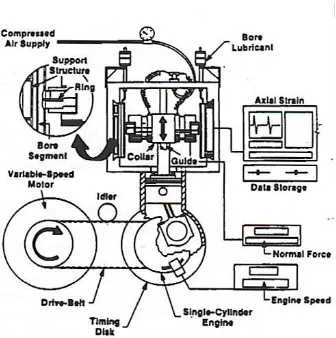
Fig. 2.4 Segmented Ring/Bore Liner test rig is an apparatus for accurate and direct comparative
friction measurements between cast iron and coated bore and ring samples and oil viscosity at
speeds from 100 to 600rpm [31].
Although the PEO coatings have excellent wear resistance, for sliding wear applications, such
alumina coating often exhibit relatively high friction coefficients against many counterface
materials. Thus, there are also many prospects for the improvement of the PEO coatings with
20
5. General corrosion characteristics of Al alloys
Neutral or nearly neutral (pH from 5 to 8.5) solutions of most inorganic salts cause negligible or
minor corrosion of Al alloys at room temperature. Any attack that occurs in such solutions is
likely to be highly localized (pitting) with little or no general corrosion. Solutions containing
chlorides are more active than other solutions. Distinctly acid or distinctly alkaline salt solutions
are generally somewhat corrosive. The rate of attack depends on the specific ions present. In acid
solutions, chlorides, in general, greatly stimulate attack. In alkaline solutions, silicates and
chromates greatly retard attack [32, 33].
Al alloys are not appreciably corroded by distilled water even at elevated temperatures (up to
180°C at least). Most commercial Al alloys show little or no general attack when exposed to
most natural waters at temperatures up to 180°C [34]. However, a small amount of water
can drastically affect resistance to certain anhydrous organic solutions, particularly halogenated
hydrocarbons. Water vapor in the air is sufficient to cause staining upon condensation, and
to support SCC (spell out??) [33]. Al alloys that do not contain Cu as a major alloying
constituent are resistant to unpolluted seawater. Among the wrought alloys, those of 5xxx series
have the highest resistance to seawater; among the casting alloys, those of the 356.0 and 514.0
types are used extensively for marine applications. Corrosion of AI alloys in seawater is mainly
of the pitting type, as would be expected from its salinity and enough dissolved oxygen as a
cathodic reactant to polarize the alloys to their pitting potentials [34].
Since one of the many applications of Al alloys is in the automotive industry, as pistons,
cylinder liners and valve seats, a knowledge of their corrosion behavior in the corrosive
21
behavior of both a Al-Si-Cu hypereutectic alloy and grey cast iron in ethanol automotive fuels.
The corrosion test medium they used was pure ethanol and ethanol with small additions (lmM)
of sulphuric acid and lithium chloride. The results showed that in pure ethanol and acid
containing ethanol, the Al-Si-Cu alloys had a higher corrosion resistance than grey cast iron,
especially in pure ethanol. However, the addition of acid to alcohol, even in small quantities,
causes dissolution of the initial oxide present on the alloy surface and impeded its formation
when immersed in the environment. Moreover, in environments containing chlorides, the
Al-Si-Cu alloys exhibited localized corrosion characteristics.
Corrosion of AI alloys can be prevented by many different methods, including the appropriate
alloy selection and system design, environment control, and the use of inhibitors and protective
coatings. The latter approach has led to the development of various surface modification
an coating techniques for AI alloys to enhance theircorrosion resistance, such as ion implantation,
sol-gel coatings, conversion coatings, CVD, PVD and thermal spraying [36-45]. Although each
of these techniques possesses its own advantages, their limitations and disadvantages are also
quite obvious. Most of these methods involve high temperatures during processing (CVD, PVD
and thermal spray) or post-treatment (sol-gel), which may damage the coating and /or substrate
[46]. In addition, sol-gel processing has been of limited use due to poor interfacial adhesion, and
shrinkage and oxidation of the substrate. Ion implantation has found limited success in increasing
the pitting potential of coatings. Conversion coatings are mainly based on chromium compounds
that exhibit good corrosion resistance, but have also been proven to be highly toxic and
carcinogenic [47, 48-53]. Since these processes have recently been reviewed, they are only
briefly mentioned here [48-53]. The following subsections concentrate on a conventional surface
22
The corrosion resistance of the PEO coatings on aluminum alloys was studied by X. Nie and
coworkers [54]. Fig. 2.5 shows the polarization curves of the alumina coated alloy (with coating
thickness of 250µm) and the untreated Al alloy substrate. Both types of sample were immersed
in 0.5M NaCl solution for 1h, 1day and 2 days before corrosion tests. A stainless steel AISI 316L
sample was also used in the corrosion test for comparison. The poor corrosion protection
property of the uncoated Al substrate resulted from the fact that the corrosion resistance
considerably decreased after the thin protective oxide film on the uncoated aluminium substrate
surface was broken down by the corrosion processes. The PEO-coated Al alloys possessed
excellent corrosion resistance in the solution-considerably better even than the stainless steel.
Fig. 2.5 Potentiodynamic polarization curves of untreated substrate materials and PEO alumina
23
6. Summary of literature review
Plasma electrolytic oxidation (PEO) of metals is a complex process combining concurrent partial
processes of oxide film formation, dissolution and dielectric breakdown. The ultimate stage of
the PEO treatment is a quasi-stationary stage of persistent anodic microdischarges, which exhibit
a progressive change in characteristics during the electrolysis. The electrolysis is always
accompanied by intensive gas evolution and localised metal evaporation due to the plasma
thermochemical reactions in the microdischarges.
Four different stages of the PEO process have been identified, characterised by various formation
mechanisms: (i) anodizing, (ii) anodizing film melted and broken down, (iii) micro-arc discharge
and oxide coating formation, and (iv) coating composition fused and re-crystallized. The PEO
coating has a three layers structure, i.e., porous outer layer, dense layer and very thin inner dense
layer.
The PEO process can greatly increase hardness and corrosion resistance for Al, Mg and Ti alloys.
However, there is not much research that has been done on A356 Al casting alloy for both wear
and corrosion prevention in engine applications which E85 fuel or deicing salt may get involved.
The PEO coating usually has high coefficient of friction. There is a need of development of a
low frictional oxide composite coating. Therefore, the research in thesis was to develop PEO
coatings on A356 Al alloy which would have high wear and corrosion resistance and low friction
24
References
[1] G.A. Markov and G.V. Mmarkova, USSR Patent 526961, Bulletin of Inventions, 32 (1976), 1
[2] A.V. Nikolaev, G.A. Markov, B.I. Peshchevitskij, Izv. SO AN SSSR. Ser. Khim. Nauk, 5 (12)
(1977), 32.
[3] G.A. Markov, V.V. Tatarchuk, M.K. Mironova, Izv. SO AN SSSR. Ser. Khim. Nauk, 3 (7)
(1983), 34.
[4] L.A. Snezhko, L.A. Beskrovnyj, Yu.M. Nevkrytyj, V.I. Tchernenko, Zashch. Met., 16 (3)
(1980), 365.
[5] L.A. Snezhko, G.V. Rozenboym, V.I. Tchernenko, Zashch. Met.,17 (5) (1981), 618.
[6] L.A. Snezhko, V.I. Tchernenko, Elektron. Obrab. Mater., (2) (1983), 25.
[7] L.A. Snezhko, V.I. Tchernenko, Elektron. Obrab. Mater., (4) (1983), 38.
[8] V.I. Tchernenko, L.A. Snezhko, C.B. Tchernova, Zashch., Met. 20 (3) (1984), 454.
[9] L.A. Snezhko, S.G. Pavlus, V.I. Tchernenko, Zashch. Met., 20 (4) (1984), 292.
[10] G.A. Markov, M.K. Mironova, O.G. Potapova, Izv. AN SSSR. Ser. Neorgan. Mater., 19 (7)
(1983), 1110
[11] A.A. Petrosyants, V.N. Malyshev, V.A. Fyedorov, G.A. Markov, Trenie Iznos, 5 (2) (1984),
350.
[12] V.N. Malyshev, S.I. Bulychev, G.A. Markov, V.A. Fyedorov, A.A. Petrosyants, V.V.
Kudinov, M.H. Shorshorov, Fiz. Khim. Obrab. Mater., (1) (1985), 82.
[13] V.A. Fyedorov, V.V. Belozerov, N.D. Velikosel’skaya, S.I. Bulychev, Fiz. Khim. Obrab.
Materialov, 4 (1988), 92.
[14] V.S. Rudnev, P.S. Gordienko, preprint no. 3384-B87, Inst. Khimii DVO AN SSSR,
25
[15] O.A. Khrisanfova, P.S. Gordienko, preprint no. 2986-B89, Inst. Khimii DVO AN SSSR,
Vladivostok, 1987.
[16] P.S. Gordienko, P.M. Nedozorov, L.M. Volkova, T.P. Yarovaya, O.A Khrisanfova, Zashch.
Met., 25 (1) (1989), 125.
[17] P. Kurze, W. Krysmann, G. Marx, Z. Wiss, Tech. Hochsch. Karl-Marx-Stadt, 24 (1982),
139.
[18] K.H. Dittrich, W. Krysmann, P. Kurze, H.G. Schneider, Cryst. Technol., 19 (1) (1984), 93.
[19] W. Krysmann, P. Kurze, K.H. Dittrich, H.G. Schneider, Cryst.Technol., 19 (7) (1984), 973.
[20] P. Kurze, J. Schreckenbach, T. Schwarz, W. Krysmann, Metalloberflaeche, 40 (12) (1986),
539.
[21] L.S. Saakian, A.P. Yefremov, L.Y. Ropyak, A.V. Apelfeld, CorrosionControl and
Environment Protection. Informative survey, VNIIOENG, Moscow, (6), 1986.
[22] V.A. Fyedorov, A.G. Kan. R.P. Maksutov, Surface Strengthening of Oil & Gas Trade
Facilities by Micro Arc Oxidation, VNIIOENG, Moscow, (6) 1989.
[23] G.A. Markov, B.S. Gizatullin, I.B. Rychazhkova, USSR Patent 926083, Bulletin of
Inventions, 17, 1982.
[24] L.A. Snezhko, V.I. Techernenko, USSR Patent 973 583, Bulletin of Inventions 23, 1982.
[25] P. Kurze, W. Krysmann, G. Marx, K.H. Dittrich, DDR Patent DD-WP C25 D/236988(5).
[26] A.L. Yerokhin, X. Nie, A. Leyland, A. Matthews, S.J. Dowey, Surface & Coatings
Technology, 122 (1999), 73-93
[27] www.techplate.com.tw, supported by Techplate International Co., Ltd.
[28] A.A. Voevodin, A.L. Yerokhin, V.V Lyubimov, M.S. Donley, J.S. Zabinski, Surface &
26
[29] A.L. Yerokhin, A.A. Voevodin, V.V. Lyubimov, J. Zabinski, M. Donley, Surface &
Coatings Technology, 110 (1998), 140-146.
[30] X. Nie, A. Leyland, H.W. Song, A.L. Yerokhin, S.J. Dowey, A. Matthews, Surface and
Coatings Technology, 116-119 (1999), 1055-1060
[31] V.D.N Rao, H.A. Cikanek, B.A. Boyer, SAE paper, 970022, 1997
[32] R. Winston Revie, Uhlig's Corrosion Handbook (2nd Edition), John Wiley & Sons
Inc, Canada, 2000.
[33] R.Baboian, Corrosion Tests and Standards: Application and Interpretation.
Philadelphia, PA: ASTM, 1995
[34] R. Winston Revie, Uhlig’s Corrosion Handbook (2nd Edition), John Wiley & Sons
Inc, Canada, 2000.
[35]S.M. Traldi, I. Costa, J.L. Rossi, Key Engineering Materials, 189-191 (2001) 352-357
[36] X. Zhang, S. Lo Russo, S. Zandolin, A. Miotello, E. Cattaruzza, P.L. Bonora, L, Corrosion
Science 43 (2001) 85-97.
[37] P. Preston, R. Smith, A. Buchanan, J.M. Williams, Scripta Metallurgica et Materialia
32 (1995) 2021-2027.
[38] M. Sheffer, A. Groysman, D. Mandler, Corrosion Science 45 (2003) 2893-2904.
[39] J. Masalski, J. Gluszek, J. Zabrzeski, K. Nitsch, P. Gluszek, Thin Solid Films 349 (1-2)
(1999) 186-190.
[40] J. Zhao, L. Xia, A. Sehgal, D. Lu, R.L. McCreery, G.S. Frankel, Surface and Coatings
Technology 140(2001) 51-57
[41] C. Taschner, B. Ljungberg, V. Alfredsson, I. Endler, A. Leonhardt, Surface and
27
[42] A. Larsson, M. Halvarsson, S. Ruppi, Surface and Coatings Technology 111 (1999)
191-198
[43] J.M. Schneider, W.D. Sproul, A.A. Voevodin, A. Matthews, Journal of Vacuum
Science and Technology A- Vacuum, Surfaces, and Films Part 15 (1997) 1084-1088.
[44] D.E. Ashenford, F. Long,W.E. Hagston, B. Lunn, A. Matthews, Surface and
Coatings Technology 119 (1999) 699-704.
[45] B.H. Kear, Z. Kalman, R.K. Sadangi, G. Skandan, J. Colaizzi, W.E. Mayo, J. Thermal
Spray Technology 9 (2000) 483-487
[46] X. Nie, E.I. Meletis, J.C. Jiang, A. Leyland, A.L. Yerokhin, A. Matthews, Surface and
Coatings Technology 149 (2002) 245-251
[47] R.L. Twite, G.P. Bierwagen. Progress in Organic Coatings 33 (1998) 91-100
[48] W.A. Badawy, F.M. Al-Kharafi, Corrosion Science. 39(1997) 681-700. 123
[49] A.Y. El-Etre, Corrosion Science 43 (2000) 1031-1039.
[50] S. Pyun, S. Moon, Journal of Solid State Electrochemistry 3 (1999) 331-336.
[51] C.M.A. Brett, I.A.R. Gomes, J.P.S. Martins, Journal of the Electrochemical Society
24 (1994) 1158-1163.
[52] B. Shaw, E. Sikora, K.Kennedy, P. Miller, E. Principe, Advances in Coatings
Technologies for Surface Engineering. Proceedings of a Symposium held at the Annual
Meeting of The Minerals, Metals and Materials Society, 1996,287-304
[53] R.L. Twite, G.P. Bierwagen, Progress in Organic Coatings 33 (1998) 91-100.
[54] X. Nie, E.I. Meletis, J.C. Jiang, A. Leyland, A.L. Yerokhin, A. Mathews, Surface &
28
Chapter 3
EXPERIMENTAL PROCEDURES
1. Pin-on-disc/reciprocating tribological test
The wear tests were carried out on PEO coatings, A356 Ingot substrate and oxide coating by
use of a Sciland Pin/Disc Tribometer PCD-300A (see Fig. 3.1) at room temperature. Only
one mode was used: reciprocating mode (sliding speed: 0.08 m/s) for the curved samples. The
tribological behavior of the coatings under dry and lubrication conditions were studied at a
normal load of 15N against an steel pin (AISI 52100, hardness HRC 59-60). A 1000m sliding
Fig. 3.1 Sliding tribotester attached on (a) Sciland Pin/Disc Tribometer PCD-300A (b) load
cell and cantilever beam, (c) sample holder for reciprocating mode (d) sample holder plus load
a
c d
29
distance was used for all PEO coatings. The same test conditions were used for the engine block
coating but the test was used at oil condition (5W20). However, only a 250m sliding distance
was used for the coating and substrate under the dry condition, and its surface profile was
measured across the wear track to study its width and depth.
2. Potentiodynamic polarization testing
Potentiodynamic polarization is a technique where the potential of the electrode is monitored at a
selected rate by application of a current through the electrolyte. By using the DC polarization
technique, information on the corrosion rate, pitting susceptibility, passivity, as well as the
cathodic behavior of an electrochemical system may be obtained.
In a potentiodynamic experiment, the driving force such as the potential voltage for anodic or
cathodic reactions is controlled, and the net change in the reaction rate such as current is
observed. The potentiostat (SP-150, Bio-logic brand instrument used for this research) measures
the current which must be applied to the system for achieving the desired increase in driving
force, known as the applied current. As a result, at the open circuit potential the measured or
applied current should be zero. [1, 2]
A typical schematic anodic polarization curve is shown in figure 3.2. The scan starts from point 1
and progresses in the positive (potential) direction until termination at point 2. The open circuit
potential is located at point A. At this point, the sum of the cathodic and anodic reaction rates on
the electrode surface is zero. The active region is the region B where metal oxidation is the
dominant reaction at this area. Point C is the passivation potential, and after the applied potential
increases above this value the current density decrease with increasing potential (region D), until
30
reached a sufficiently positive value (point F, also called as breakaway potential) the applied
current rapidly increases (region G). This increase is depending on the alloy/environment
combination. For some systems such as aluminum alloys in salt water this sudden increase in
current cause the pitting corrosion. [1-3]
Figure 3.2 Typical polarization curve [1].
A schematic cathodic polarization scan is shown in Figure 3.3. In a cathodic potentiodynamic
scan, the potential is changed from point 1 in the negative direction to point 2. The open
circuit potential is located at point A. Region B represents the oxygen reduction reaction which
depending on the pH and dissolved oxygen concentration in the solution. Because this reaction
is limited by how fast oxygen may diffuse in solution there will be an upper limit on the rate
of this reaction which is called limiting current density. Further decrease in the applied
potential result in no change in the reaction rate which causes the measured current remains
the same (region C). Eventually, the applied potential becomes sufficiently negative for
another cathodic reaction to become operative as illustrated at point D. As the potential and
31
region E. This additional reaction is typically the reduction of other species in the environment
such as the hydrogen evolution reaction which called the water reduction reaction. [1]
Figure 3.3 Theoretical cathodic polarization scan. [1]
For reactions which are essentially activation controlled, the current density can be expressed as
a function of the overpotential, η, which is expressed in equation [3]
Eq.3.1
Equation (3.1) is known as the Tafel equation, where β is the Tafel slope, i is the
applied current density, and i0 is the exchange current density.
32
3. Zero Resistance Ammetry
A zero resistance ammeter is a current to voltage converter that produces a voltage output
proportional to the current flowing between its to input terminals while imposing a ’zero’ voltage
drop to the external circuit. By using this electrochemical technique, galvanic currents between
dissimilar electrode materials are measured with a zero resistance ammeter. This technique can
be used to nominally identical electrodes in order to find changes occurring in the corrosive
environment and thus act as an indicator of changing corrosion rates.[2]
The main principle of the technique is that differences in the electrochemical behavior of two
electrodes exposed to a process stream give rise to differences in the redox potential at these
electrodes. When the two electrodes are externally electrically connected, the more noble
electrode becomes predominantly cathodic, then the more active electrode becomes
predominantly anodic and sacrificial. After the anodic reaction is relatively stable the galvanic
current monitors the response of the cathodic reaction to the process stream conditions. When the
cathodic reaction is stable, it monitors the response of the anodic reaction to process fluctuations.
[2]
Measurements of galvanic currents between silver and platinum coupled metals are based on the
use of zero resistance amperometry (ZRA). A potentiostat controlled with asoftware were setup
as a ZRA. The working electrode wire and the reference electrode wire combined to one served
as working electrode. The counter electrode wire was not used. The ground wire connected to
pure platinum served as working electrode.
33
Fig. 3.5 (a, b) View of three-electrode cell and electrochemical corrosion testing equipment.
(c) General galvanic corrosion test and (d) ZRA test cells arrangements.
RE : reference electrode; WE: working electrode CE: counter electrode
References
[1] Mythili Koteeswaran,CO2 and H2S Corrosion in Oil Pipelines Master Thesis of University
of Stavanger June 2010
[2] Pierre R. Roberge Chapter 4. Corrosion Inspection and Monitoring Copyright @ 2007 by
John Wiley & Sons, Inc.
[3] Denny A. Jones, Principles and Prevention of Corrosion, 2nd Edition, 1996, Prentice Hall,
Upper Saddle River, NJ.
a b
c d
WE
RE
CE
RE
34
CHAPTER 4
CORROSION PROPERTIES OF PLASMA ELECTROLYTIC
OXIDATION CERAMIC COATINGS ON AN A356 ALLOY TESTED IN
AN ETHANOL-GASOLINE FUEL (E85) MEDIUM
1. INTRODUCTION
Government organizations and automotive manufactures have been trying to find alternative
fuels to substitute for gasoline and diesel fuels because of low accessibility of energy resources
and environmental issues. Ethanol which acts as a bio-based energy resource and renewable
chemical can reduce both crude oil consumption and the effect of environmental pollution. The
use of ethanol blended gasoline as an alternative fuel has recently shown promising results in
several countries [1, 2]. The problem of ethanol blended fuel is that associated with corrosion of
the materials used in vehicles. In addition, the corrosiveness of the fuel depends on the content
and kind of contaminations [3, 4]. Water is expected to be present as a contaminant in small
amounts in commercial fuels such as ethanol-gasoline [5, 6] and could cause the corrosion
problems to the materials which come into contact with. When dissimilar materials are involved,
the galvanic corrosion becomes even more problematic. Aluminium (Al) casting alloys have
widely been used in automotive engine heads and cylinder blocks where a number of Al and
steel couplings exist. To protect the Al from corrosion, a PEO coating technique has been used,
which operates at potentials above the breakdown voltage of an oxide film growing on the
surface of a passivated metal anode (i.e. Al in this case) and is characterized by multiple arcs
moving rapidly over the treated surface. Complex compounds can be synthesized inside the high
voltage breakthrough channels formed across the growing oxide layer. Plasma thermochemical
35
the substrate surface. At a particular combination of electrolyte composition and current regime
the discharge modifies the microstructure and phase composition of the substrate from a metallic
alloy to a complex ceramic oxide. As a result, an oxide coating with excellent adhesion can be
achieved on aluminium alloy components [7, 8].
In this study, PEO oxide coatings were prepared under different current modes. Potentiodynamic
polarization and Zero Resistance Ammetry (ZRA) [9] corrosion testing methods were used to
evaluate the corrosion properties of coated and uncoated Al alloys (A356) in an alternative fuel.
Effects of the current modes on the coating morphologies and anti-corrosion performance were
particularly discussed in this paper.
2. Experimental Details
Circular coupons (20×20×5mm) cut from an A356 alloy were ground and polished before
washing in water and then drying in air. The composition of the alloy is 0.25 Cu max, 0.20 to
0.45Mg, 0.35 Mn max , 6.5 to 7.5 Si, 0.6 Fe max, 0.35 Zn max, 0.20 Ti max, 0.05 other (each)
max, 0.15 others(total) max, bal Al. A PEO coating preparation system as described in Ref. [10]
was used to produce the oxide ceramic coating on the coupon samples. The coatings were
prepared in an alkaline electrolyte (KHPO4, 12g/l) using different current modes [11]. Four
coating samples were prepared: Sample A was coated by using unipolar current mode for 10
minutes, Sample B by using bipolar current mode for 10 minutes, Sample C by using combined
unipolar (for 5 min) and bipolar (for 5 min) current mode for 10 minutes in total, and Sample D
by switching the sequence for unipolar and bipolar compared with Sample C. All samples were
treated under the same current density 500A/m2.


![Fig. 2.3 Illustrates the structure of the PEO coating [27].](https://thumb-us.123doks.com/thumbv2/123dok_us/1422957.1174836/31.612.76.475.377.634/fig-illustrates-structure-peo-coating.webp)


![Figure 3.2 Typical polarization curve [1].](https://thumb-us.123doks.com/thumbv2/123dok_us/1422957.1174836/45.612.73.289.193.380/figure-typical-polarization-curve.webp)
![Figure 3.4 Tafel slope calculation.[3]](https://thumb-us.123doks.com/thumbv2/123dok_us/1422957.1174836/46.612.75.340.129.310/figure-tafel-slope-calculation.webp)


