Scholarship at UWindsor
Scholarship at UWindsor
Electronic Theses and Dissertations Theses, Dissertations, and Major Papers
1-1-1970
An alphanumeric text generator for a computer display.
An alphanumeric text generator for a computer display.
William E. Mennie University of Windsor
Follow this and additional works at: https://scholar.uwindsor.ca/etd
Recommended Citation Recommended Citation
Mennie, William E., "An alphanumeric text generator for a computer display." (1970). Electronic Theses and Dissertations. 6621.
https://scholar.uwindsor.ca/etd/6621
This online database contains the full-text of PhD dissertations and Masters’ theses of University of Windsor students from 1954 forward. These documents are made available for personal study and research purposes only, in accordance with the Canadian Copyright Act and the Creative Commons license—CC BY-NC-ND (Attribution, Non-Commercial, No Derivative Works). Under this license, works must always be attributed to the copyright holder (original author), cannot be used for any commercial purposes, and may not be altered. Any other use would require the permission of the copyright holder. Students may inquire about withdrawing their dissertation and/or thesis from this database. For additional inquiries, please contact the repository administrator via email
INFORMATION TO USERS
This manuscript has been reproduced from the microfilm master. UMI films
the text directly from the original or copy submitted. Thus, some thesis and
dissertation copies are in typewriter face, while others may be from any type of
computer printer.
The quality of this reproduction is dependent upon the quality of the
copy submitted. Broken or indistinct print, colored or poor quality illustrations
and photographs, print bleedthrough, substandard margins, and improper
alignment can adversely affect reproduction.
In the unlikely event that the author did not send UMI a complete manuscript
and there are missing pages, these will be noted. Also, if unauthorized
copyright material had to be removed, a note will indicate the deletion.
Oversize materials (e.g., maps, drawings, charts) are reproduced by
sectioning the original, beginning at the upper left-hand comer and continuing
from left to right in equal sections with small overlaps.
ProQuest Information and Learning
300 North Zeeb Road, Ann Arbor, Ml 48106-1346 USA 800-521-0600
AN ALPHANUMERIC TEXT GENERATOR
FOR A COMPUTER DISPLAY
BY
WILLIAM E. MENNIE
A T hesis
Submitted to th e F a cu lty o f Graduate S tu d ies through the Department o f E l e c t r i c a l E n gin eering i n P a r t ia l F u lfillm e n t
o f the Requirements fo r the Degree o f Master o f Applied S cien ce a t th e
U n iv e r sity o f Windsor
Windsor, Ontario
1970
®
UMI
UMI Microform EC52816
Copyright 2007 by ProQuest Information and Learning Company. All rights reserved. This microform edition is protected against
unauthorized copying under Title 17, United States Code.
ProQuest Information and Learning Company 789 East Eisenhower Parkway
P.O. Box 1346 Ann Arbor, Ml 48106-1346
A (3 6 7 2 31
APPROVED
Q
2 1 8 1
2
This t h e s is d e sc r ib e s th e l o g i c a l d e sig n and. im plem entation o f th ree
v a r ia tio n s o f an alpha-num eric t e x t gen erator fo r d isp la y in g computer
inform ation on a cathode ray tube ( c . r . t . ) .
Each ch aracter i s generated by in t e n s if y in g d o ts which are s e le c t e d
from a 5 x 7 m a trix . S e le c t io n o f th e d o ts i s performed by d i g i t a l l o
g ic c i r c u i t s which su p p ly unblanking p u lse s to th e Z -a x is o f th e c . r . t .
i n synchronism w ith a r a s t e r g en era to r.
Three methods o f r a s t e r g en era tio n are d e sc r ib e d . This perm its the
ch a ra cter generator to be u sed i n system s o f v a ry in g c o s t and co m p lex ity .
The most complex method u se s h o r iz o n ta l and v e r t i c a l d i g i t a l to
analogue (d/a) co n v erters to generate th e r a s t e r as w e ll as t o p o s it io n
each ch a ra cter. This perm its s e v e r a l new ch a ra cter o p era tio n s to be
provided by hardware.
Three s i z e s o f ch a ra cters may be generated and two s i z e s may be
hardware p o s itio n e d as s u b s c r ip ts o r s u p e r s c r ip t s . Back sp acin g en a b les
s u p e r sc r ip ts to be p o s itio n e d above s u b s c r ip ts o r ch a ra cters to be super
im posed. T abulation lo c a t e s up to e ig h t v e r t i c a l columns. C arriage r e
tu rn s may be made to any one o f n in e le ft - h a n d margin p o s it io n s . Line
fe e d s may be s in g le or double sp aced . Spacing between l i n e s and char
a c te r s i s a u to m a tic a lly adjusted, accordin g to th e ch aracter s i z e u sed .
C ontrol o f th e ch a ra cter gen erator may be accom plished through an
ASR 33 T eletype and a few fu n c tio n k e y s. Thus th e t e x t generator i s
e a s ie r to op erate than most co n v e n tio n a l ch a ra cter g en era to rs.
i i
The t e x t gen erator fu n c tio n s e q u a lly w e l l w ith a sto ra g e c . r . t . or
w ith a r e fr e sh memory s in c e i t i s capable o f g en era tin g up to 53»000
ch a ra cters per second .
The s i m p li c it y and v e r s a t i l i t y o f the t e x t g en erator makes i t
s u it a b le fo r n e a r ly e v ery a p p lic a t io n which u t i l i s e s a c . r . t . d is p la y
s in c e i t can r e a d ily be t a i l o r e d to such u s e r ’s needs as the a d d itio n
o f a graphics c a p a b il it y .
xax
The author w ishes to ex p ress h is a p p r e c ia tio n to Dr. P . A. V.
Thomas fo r s u g g e stin g t h i s p r o j e c t and fo r h is h e lp f u l c r it ic i s m .
Acknowledgement must a ls o go t o th e N a tio n a l R esearch C ouncil o f Canada
fo r the f in a n c ia l a s s is t a n c e which made t h i s p r o je c t p o s s ib le .
i v
TABLE OF CONTENTS
Page
ABSTRACT ... . . . i i
ACKNOWLEDGEMENTS ... . . . i v
TABLE OF CONTENTS . . . ... v
LIST OF ILLUSTRATIONS... v i i i LIST OF TABLES . ... x i I . INTRODUCTION 1 .1 The D e s ir a b il it y o f Cathode Ray Tube D isp la y s * . 1 1 .2 Some Current Methods o f C haracter G eneration • • 4 1 . Beam Shaping 4 2 . Scanning . . . 4
3> Stroke or Waveform . . . 3
4 . Dot Generation ... 5
5* Software Techniques . . . . . 6
1 .3 The R efresh Problem . . . 7
1 .4 Three Proposed Methods o f C haracter G eneration . 8 1 .5 Im plem entation . . . 9
I I . GENERATION OF UNIQUE CHARACTER PULSE TRAINS 2 .1 Reasons fo r S e le c t in g the 5 x 7 Dot M atrix . . . 10
2 .2 The Unique P ulse Train . . . 12
2 .3 General D e sc rip tio n o f th e C haracter Dot Generator 12 2 .4 The C o u n te r ... 1^
2 .5 The Counter Decoder . . . 17
2 .6 P u lse S e le c t io n Gates . . . . . . 20
v
2 .8 The C haracter Decoder ... 24
I I I . TWO METHODS OF BEAM POSITIONING USING AN ANALOGUE HORIZONTAL SWEEP 3*1 In tr o d u ctio n ... 26
3 .2 H o rizo n ta l and. V e r t ic a l Sweep Method . . . 26
3 .3 C haracter Generator w ith H o r iz o n ta l Sweep and V e r t ic a l D/A C onverter ... . . . 34
IV . BEAM POSITIONING BY USING D/A CONVERTERS 4 .1 In tr o d u ctio n % 4 . 2 One P o s s ib le Method ... . . . 38
4 .3 The General Method Used 39 4 . 4 C haracter S iz e S e le c t io n 42 4 .5 C haracter Count C on trol C ir c u itr y ... 4?
4 .6 X R e g is te r Count S e l e c t i o n . 49
4 .7 The X R e g i s t e r ... 51
4 .8 Y R e g iste r Count S e le c t io n . . . 54
4 .9 Y R e se t C ir c u itr y . . . ... . . . 58
4 .1 0 The Y R e g is te r . . . . 61
4 .1 1 UP-DOWN Count S e le c t io n C ir c u itr y . . . 61
V. SPECIAL CHARACTERS 5 .1 In tr o d u c tio n . . . • 64
5 .2 S p e c ia l C haracter Decoder . . . 64
5 .3 The Back Space . . . 68
5*4 The Line Feed. 68
v i
Page
5 .5 The C arriage Return and Tabulate . . . 69
1 . C arriage Return . . . . . . 69
2 . Tabulate . . . . 73
VI. CONTROL AND TESTING OF TEE A/N GENERATOR 6 .1 R efresh and. C ontrol o f th e a/N D isp la y . . . 79
6 .2 The
i / o
T e r m in a l... 826 . 3 T est R e su lts . . . . . 86
V II. CONCLUSIONS ... 88
APPENDIX I CHARACTER LEST AND ASCII CODES... 92
APPENDIX I I CHARACTER DOT PATTERNS AND PULSE NUMBERS . . . . 9^
APPENDIX I I I CHARACTER SIZE AND POSITION EXAMPLES.... 100
APPENDIX IV INSTRUCTION AND DATA WORDS... 101
APPENDIX V TIMING DIAGRAMS ... 102
APPENDIX VI LOGIC NOTATION . 105
APPENDIX VII TWO OPERATING SPEEDS FOR HORIZONTAL AND VERTICAL SWEEP CHAR AC'TER GENERATION... 106
REFERENCES ... 107
VITA AUCTORIS... 108
v i i
Figure Page
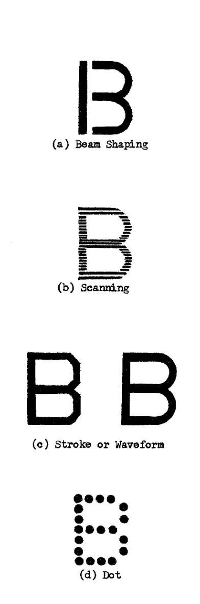
1 .1 Examples o f C haracters Generated by D iff e r e n t Methods 3
2.1 Use o f th e Unique Pulse Train . . . 11
a . H o rizo n ta l D e fle c tio n V oltage Waveform
b . V e r t ic a l D e fle c tio n Waveform
c . P u lse Train Required to Form th e Character 'A'
d . C haracter Which R e su lts From Combined Waveforms
2 .2 Block Diagram o f C haracter Dot Generator . . . 13
2 .3 Counter fo r H o rizo n ta l Sweep Method . ... 15
2 . ^ High Speed Counter fo r H o rizo n ta l d/a Converter Method 16
2 .5 The Counter Decoder 18
2 .6 a The B a sic 5 x 7 Dot M atrix . . . 19
2 .6 b The P u lse S e le c t io n Gates 19
2 .7 The B u ffer R e g is te r ... 21
2 .8 The C haracter Decoder ... 23
3 .1 Output o f O r ig in a l Character Generator ... 2?
3 .2 Character Generator With H o rizo n ta l and V e r tic a l Sweep 29
3 .3 H o rizo n ta l Sweep and V e r tic a l D/A Converter Method . 32
3 .4 Timing Waveforms fo r H o rizo n ta l Sweep and V e r tic a l D/A Converter . . . 33
a . H orizo n ta l D e fle c tio n V oltage Waveform
b . Clock P u lses
c . Y -R eset P u lses to C lear the L east S ig n ific a n t Three B its
Figure Page
d . Count Up In th e Y D ir e c tio n
e . V e r t ic a l D e fle c tio n Waveform
4 .1 One P o s s ib le Method Using d/a C o n v e r t e r s ... . 37
4 .2 a Normal Counter ... 40
4 .2 b Counter Capable o f Counting i n Any P o s itio n ... 40
4 .3 Siae S e le c t io n C ir c u itr y ... 43
4 .4 a Dot M atrix . . . ... . . . 46
4 .4 b C haracter Count C ontrol C ir c u itr y . . . ... 46
4 .5 X Count S e le c t io n C ir c u itr y ... 50
4 .6 a X R e g is te r (L ea st S ig n if ic a n t B i t s ) . . . 52
4 .6 b X R e g is te r (Most S ig n if ic a n t B i t s ) . . . 53
4 .7 Y Count S e le c t io n C i r c u i t r y ... ... 56
4 .8 Y R e se t C ir c u itr y ... • 57
4 .9 a Y R e g is te r (L east S ig n if ic a n t B i t s ) . . . 59
4 .9 b Y R e g is te r (Most S ig n if ic a n t B i t s ) ... 60
4 .1 0 UP-DOWN Count S e le c t io n C ir c u itr y . . . 62
5 .1 S p e c ia l C haracter D e c o d e r ... 65
5 .2 a G eneration o f th e Line Feed P u l s e ... 67
5.2 b Use Margin R e g iste r and Space F lip -F lo p . . . 67
5 .3 X R e g is te r C lear C ir c u itr y . . . 70
5 .4 C ir c u itr y fo r Loading X R e g is te r During C arriage Return and. Tabulate ... 71
5 .5 Tabulate Algorithm ... 75
5 .6 C ir c u itr y Required To Generate 6 4 's Count During Tab u la t io n . . . . . . . 76
6 .1 a D evice S e le c to r Schematic ... 80
i x
6 .1 b a/N C on trol U n i t ... 80
6 .2 Block Diagram o f i / o Terminal . . . 81
6 .3 Three R a ster Techniques (Photographs) . ... 84
a . H o rizo n ta l and V e r t ic a l Sweep
b . H o rizo n ta l Sweep and V e r t ic a l D/a Converter
c . H o rizo n ta l and. V e r t ic a l D/A Converter
6 .4 a Three C haracter S iz e s (P h o to g r a p h )... 85
6 .4 b Tabulate and C arriage Return ( P h o t o g r a p h ) ... 85
x
LIST OF TABLES
Table Page
4 .1 X R e g iste r Counting C a p a b ilitie s ... 49
4 .2 Y R e g iste r Counting C a p a b ilitie s 54
4 .3 Y-Reset P o s itio n s . . . 55
5 .1 Tabulate and Margin P o s itio n s 69
x i
INTRODUCTION
1 .1 The D e s i r a b i l i t y o f Cathode Ray Tube D isp la y s
D ig it a l computers are capable o f ex trem ely ra p id com putation and
data m an ip u lation . S in ce m echanical d e v ic e s such as ty p e w r ite r s , l i n e
-p r in t e r s , card rea d ers and -p l o t t e r s are g e n e r a lly much slow er than th e
computer, th e computer must norm ally slow down to match th e speed o f the
in p u t-o u tp u t
( i / o )
d e v ic e s which are tr a n s m ittin g data to and r e c e iv in gdata from th e computer. This can vary from a person ty p in g a few char
a c te r s per minute to a l i n e p r in t e r capable o f o u tp u ttin g perhaps 3»000
ch a ra cters per secon d .
To avoid t h i s problem, modern h ig h -sp eed computers g e n e r a lly tr a n s
f e r th e computed in fo rm a tio n in t o b u ffe r s which can a c c e p t data a t the
com puter's h igh speed and th en su p p ly t h i s data to th e output d e v ic e a t
i t s own lower sp eed . The r ev e r se o p era tio n can be used fo r lo a d in g data
in t o th e computer. Thus th e computer i s a b le to in t e r a c t w ith s e v e r a l
in p u t-o u tp u t d e v ic e s to ensure th a t th e h ig h computing c a p a b ilit y i s
used to the b e s t advantage. For th e m a jo rity o f s c i e n t i f i c and b u sin ess
a p p lic a tio n s t h i s type o f in t e r a c t io n i s s a t i s f a c t o r y . The job i s sub
m itted a t one tim e and th e computed r e s u lt s are o b ta in ed on paper a t a
l a t e r tim e.
More r e c e n t ly , computers have found t h e ir way in t o such v a r ie d areas
13
as data r e t r i e v a l , com puter-aided in s t r u c t io n (CAI) and com puter-aided
d e sig n (CAD). These u se s in tro d u ce two new problems which the above
1
2
mentioned
i / o
d e v ic e s are n o t r e a d ily a b le to cope w ith . F i r s t , theu ser i s in t e r e s t e d i n ra p id r e s u lt s and cannot a ffo r d lo n g d e la y s w h ile
w a itin g fo r p r in te d m a t e r ia l. O b viously, he cannot s i t i n f r o n t o f a
l in e - p r in t e r a l l day. S econ d ly, th e u se r o ft e n w ish es to i n t e r a c t w ith
th e computer. How i s he a b le to o b ta in a c ce ss to th e in fo rm a tio n which
has been computed b u t i s s t i l l i n th e output b u ffe r and n o t y e t p r in ted
so th a t he may r a p id ly d ecid e i f th e r e s u l t s are what he expected ?
The b e s t s o lu t io n to th e problem developed so fa r i s th e use o f a
cathode ray tube ( c . r . t . ) d is p la y . C haracter w r itin g speeds i n e x c e ss
o f 50,000 per second are e a s i l y a c h ie v ed . Thus computed data can be
tra n sm itted and d is p la y e d alm ost in s ta n ta n e o u s ly . The a d d itio n o f a
lig h t - p e n and fu n c tio n keys to th e normal ty p ew r ite r keyboard, adds th e
p o s s i b i l i t y o f m odifying or p o in tin g to s e le c t e d a rea s o f th e d is p la y
to o b ta in th e a t t e n t io n o f th e computer fo r ra p id two-way in t e r a c t io n
between th e computer and th e u s e r . Adding a grap hics c a p a b il it y en
a b le s p i c t o r i a l as w e l l a s p r in te d in fo rm a tio n to be d is p la y e d .
Another im portant advantage o f c . r . t . d is p la y s i s th e p o s s i b i l i t y
o f having s e v e r a l c . r . t . scr e en s d is p la y in g th e same in fo rm a tio n sim
u lt a n e o u s ly . This i s advantageous, fo r example, i n modern a ir p o r ts
where computers are used i n f l i g h t sch ed u lin g . D isp la y s p laced i n
s t r a t e g i c lo c a t io n s throughout the term in al can im m ed iately inform the
s t a f f and p u b lic o f a r r iv a l and departure tim e s.
The fe a tu r e s mentioned above make c . r . t . d is p la y s an a t t r a c t iv e
and e f f i c i e n t method o f p ro v id in g communication between the computer
and i t s u s e r s . I n a d d itio n , th ey can be made e s t h e t i c a l l y p le a s in g to
th e eye and t h e i r q u ie t o p e r a tio n perm its th e u se r to work i n a p e a c e fu l
and th o u g h t-stim u la tin g environm ent.
B
(a ) Beam Shaping
(b ) Scanning
B B
( c ) Stroke or Waveform# • • • .
•
•
•
•
• • • •
•
•
•
•
• • • •
(d ) DotFigure 1.1 Examples o f C haracters Generated by D iffe r e n t Methods
Reproduced with permission of the copyright owner. Further reproduction prohibited without permission.
2 7 1 .2 Some Current Methods o f C haracter G eneration '
There are many d if f e r e n t methods o f gen era tin g ch a ra cters fo r c . r . t .
d is p la y s i n use tod ay. The most im portant requirem ent i s th a t th ey are
e a s i l y read ab le. A few o f the c u r r e n tly used methods w i l l be d e sc r ib e d .
1 . Beam Shaping
This method u t i l i z e s a s p e c i a l l y c o n str u c ted c . r . t . w ith a
s t e n c i l mask p laced i n th e path o f th e e le c t r o n beam. This s t e n c i l con
t a in s th e shape o f a l l ch a ra cters which can be d is p la y e d . The unshaped
e l e c t i o n beam generated by the a c c e le r a t in g gun o f th e tube can be de
f l e c t e d to a p a r tic u la r area o f the mask by s e l e c t i o n p la t e s w ith in the
tu b e . The beam p a sses through the mask and i s extruded i n the shape o f
the ch a r a cter . The shaped beam i s then d e f le c t e d a g a in to i t s f i n a l
p o s it io n on the s c r e e n . Although t h i s method o f ch a r a cter g en eration
i s f a s t , the tube i s ex p en siv e and th e number and shape o f the charac
t e r s i s u s u a lly q u ite lim it e d . F ig . 1 .1 a i s an example o f t h i s type o f
c h a r a c te r .
2 . Scanning
This method u t i l i z e s a scanning r a s t e r s im ila r to th a t used
i n t e l e v i s i o n . The ch a ra cter data w ith in th e g en erator i s scanned in
synchronism w ith th e r a s t e r to provide th e data r eq u ir ed to modulate
the beam. This method i s w e ll s u it e d to m u ltip le d is p la y s such as the
p r e v io u sly mentioned a ir p o r t d is p la y s in c e t e l e v i s i o n s e t s can be used
and in terco n n ected by c o a x ia l ca b le fo r a r e l a t i v e l y low c o s t d is p la y .
This method cannot r e a d ily be used fo r l i g h t pen in t e r a c t io n s in c e the
e n t ir e screen i s b eing scanned by th e r a s t e r and th e co o rd in a tes o f
the beam a t a p a r tic u la r time are n o t a c c u r a te ly known. F ig . 1 .1 b g iv e s
an example o f t h i s c h a r a c te r .
3 . Stroke o r Waveform
T his method o f g en era tin g c h a r a cter s probably perm its the
g r e a t e s t f l e x i b i l i t y o f ch a ra cter s t y l e s . The ch a ra cter i s sto r e d as
X d e f l e c t i o n , Y d e f l e c t i o n and i n t e n s i t y in fo rm a tio n . As the ch aracter
i s b ein g gen era ted , th e se th ree p ie c e s o f analogue d ata are sim u ltan e
o u s ly fe d to the X, Y and Z axes o f th e c . r . t . tu b e . The ch aracter i s ,
t h e r e fo r e , tr a c ed ou t i n much th e same manner as one would w r ite char
a c te r s by hand. This method i s v e ry f a s t bu t th e c i r c u i t r y req uired to
s to r e and su p p ly th e analogue in fo rm a tio n i s q u ite complex and e x p e n siv e.
F ig . 1 .1 c i l l u s t r a t e s th e ch a ra cters generated by t h i s method.
4 . Dot G eneration
I n t h i s method, th e ch a ra cters are composed o f a group o f
d o ts which are s e le c t e d from a b a s ic a rra y or m a tr ix . Two op era tio n s
must be performed to gen erate a ch a r a cter by t h i s method. F i r s t , the
d o t m atrix p o s it io n must be generated on th e scr e en by e it h e r a sm all
sweep r a s t e r or by d/a c o n v erters which can a c c u r a te ly p o s itio n th e beam
w ith in the a rra y . S econ d ly, some means o f d eterm ining whether to i n
t e n s i f y (unblank) th e beam a t a p a r tic u la r p o s it io n w ith in th e array
must be provided fo r each c h a r a c te r .
One o f th e most commonly used methods o f g en era tin g the i n
t e n s i f i c a t i o n in fo rm a tio n i s to u se a sm a ll core memory. I f a 5 x 7
m atrix o f d o ts i s u sed , th e memory w i l l c o n ta in 35 m agnetic co res a ls o
arranged i n a 5 x 7 m a trix . A sen se w inding i s threaded through th e
co res which correspond to th e d o ts which are req u ired to generate a
p a r tic u la r c h a r a c te r . I n a d d itio n , a s e t and r e s e t w inding i s threaded
6
through each c o r e . A ll o f th e s e t w indings o f each column are connec
te d i n s e r ie s as are th e r e s e t w indings o f each row.
To generate a ch a ra cter th e core memory i s in te r r o g a te d i n
sequence w ith the r a s t e r g e n e r a tio n . F i r s t , a l l o f th e cores o f a par
t ic u l a r column are s e t bu t th e ch a ra cter sen se w indings are d is a b le d .
Then each core i n th e column i s r e s e t i n sequence and th e sense winding
i s a c tiv a te d . Only i f the sen se w inding p asses through a core which i s
bein g r e s e t w i l l i t sen se th e changing magnetic f i e l d and c o n tr o l th e
in t e n s i f i c a t i o n o f th e corresponding p o in t i n th e c . r . t . r a s t e r . The
obvious d isadvantages o f t h i s method are th a t ch a ra cters cannot be changed
w ithout rew irin g th e core m atrix and a complete read c y c le must be per
formed fo r a l l 35 p o s s ib le d o ts i n th e m atrix making th e system q u ite
slow compared w ith o th er methods.
Other methods o f s e l e c t i n g d o ts have a ls o been u sed . One u ses
a diode m atrix which i s scanned to generate th e x and y d e f le c t io n as
w e ll as th e req uired i n t e n s i t y in fo rm a tio n .
5 . Software Techniques
In order to gen erate ch a ra cters as r a p id ly or as in e x p e n s iv e ly
as p o s s ib le , the v a rio u s hardware tech n iq u es which have been mentioned
have u s u a lly been employed to generate c h a r a c te r s. U su a lly o n ly the
type and s i z e o f th e c h a ra cter i s su p p lie d to the ch aracter gen erator.
The a c tu a l gen era tio n o f th e ch a ra cter i s accom plished a u to m a tic a lly .
With th e advent o f ex trem ely high speed random a c ce ss memories,
some manufacturers are moving away from hardware character g en era tio n .
The coordinate and i n t e n s i t y in form ation req u ired to generate a p a r tic u
l a r character i s s to r e d i n a memory as a subroutine which can e a s i l y be
m od ified t o generate any shape and s i z e o f ch a ra cter one p le a s e s ,
A ch a ra cter i s generated by s e l e c t i n g a p a r tic u la r su b ro u tin e,
The s to r e d in form ation i s then fe d to d /a co n v erters which c o n tr o l th e
beam p o s itio n in g and i n t e n s i t y whenever t h a t p a r tic u la r subroutine i s
ad d ressed. The obvious advantages o f su ch a method are f l e x i b i l i t y and
th e use o f r e l a t i v e l y u n so p h is tic a te d hardware. But u n t i l r e c e n t ly h ig h
speed memories have been v ery c o s t l y alth ou gh t h e ir p r ic e i s r a p id ly be
in g reduced now. I t may w e ll be th a t i n th e v ery near fu tu re t h i s method
o f ch a ra cter gen era tio n may overtak e th e c o n v en tio n a l hardware te c h n iq u e s,
1 .3 The R efresh Problem
I t has been im p lied above th a t h ig h speed i s a d e s ir a b le ch a ra cter
i s t i c fo r a ch a ra cter g en era to r. This can be d e s ir a b le fo r two main r ea
so n s .
F i r s t , i t was m entioned t h a t one w ish es to have th e computer tr a n s
f e r i t s computed r e s u lt s as r a p id ly as p o s s i b l e . I f one i s u t i l i z i n g a
s p e c ia l sto r a g e c . r . t . tube w hich i s capable o f s to r in g th e image tr a c ed
o u t by the e le c tr o n beam, th e computer can tr a n s fe r th e d ata to the d i s
p la y a t a f a i r l y h ig h speed (s a y 3»000 c h a r a c te r s/se c o n d ) and th e scr e en
w i l l r e t a in th e in fo rm a tio n . This type o f d is p la y cannot be u sed fo r
in t e r a c t iv e d is p la y s which u se a l i g h t pen s in c e th e d is p la y i s con
tin u ou s w ith tim e and does n o t g iv e the computer any means o f determ in
in g the p o s it io n o f the pen.
I f one i s not u t i l i z i n g a sto ra g e c . r . t . tu b e , g en era tin g the d i s
p la y once i s n o t s u f f i c i e n t s in c e i t fad es r a p id ly w ith tin ® . This
fa d e -o u t or p e r s is te n c e tim e t y p i c a l l y v a r ie s from between 20 t o 100
m illis e c o n d s depending on th e type o f phosphor used i n th e c . r . t . This
b rin g s us to th e second and m ost im p ortant need fo r a h ig h sp eed d is p la y .
To m ain tain th e in fo rm a tio n on a n o n -s to r in g c . r . t . , th e d is p la y
must c o n tin u a lly be reg en era ted o r r e fr e s h e d . This r e fr e s h in g must be
done a t a r a te which i s h ig h enough to preven t th e eye from s e e in g i t
o r th e scr e en w i l l appear to have annoying f l i c k e r . Thus th e r e f r e s h
r a te cou ld be as h ig h as 50 o r 60 frames per second depending on the
phosphor o f th e c . r . t . and background l i g h t i n g o f the room. In order
to d is p la y 1 ,0 0 0 c h a ra cters on th e s c r e e n , one must have a ch a ra cter
gen erator capable o f g e n e ra tin g 5 0 ,0 0 0 ch a r a cter s per secon d . Hence
so ftw a re c h a ra cter g e n e r a tio n i s c u r r e n t ly v e ry lim it e d due to the
amounts o f in fo rm a tio n r e q u ir e d .
1 .4 Three Proposed Methods o f C haracter G eneration
A 5 x 7 d o t m a trix was chosen to provide th e ch a ra cter r a s t e r .
The method o f s e l e c t i n g and i n t e n s i f y i n g th e c o r r e c t d o ts f o r a p a r t i
c u la r c h a ra cter i s common to a l l th r e e ch a ra cter g e n e r a to r s. This w i l l
be d is c u s s e d i n g r e a te r d e t a i l i n chapter I I .
The th re e c h a ra cter gen era to rs d i f f e r p r im a r ily i n th e method used
to generate th e 5 x 7 d o t m a trix . The f i r s t method u t i l i z e s both h o r i
z o n ta l and v e r t i c a l sweep c i r c u i t s to generate th e ch a r a cter r a s t e r . A
d/a co n v erter i s a ls o used i n th e v e r t i c a l a x is i f more th an one l i n e o f
ch a ra cters i s to be d is p la y e d .
The second method u t i l i z e s a h o r iz o n ta l sweep c i r c u i t but o n ly a
D/a co n v erter i s used i n th e v e r t i c a l a x is to generate b oth th e seven
v e r t i c a l d o t p o s it io n s i n th e m atrix and th e p o s itio n in g o f s e v e r a l l i n e s
o f t e x t .
The f i n a l method, u se s a d/a co n v e rter fo r th e h o r iz o n ta l p o s it io n
in g as w e ll as a v e r t i c a l d/a co n v erter s im ila r to t h a t used i n the s e c
ond method.
The th ree methods o f g en era tin g the ch aracter r a s te r s have been
co n stru cted and t e s t e d . They w i l l be d isc u sse d i n d e t a i l i n chapters
TTT and IV along w ith t h e ir advantages and d isa d v a n ta g es.
10
1 .5 Implementation
The c i r c u i t r y which w i l l be d e scr ib e d i n th e remainder o f t h i s
t h e s i s was co n stru cted from D i g i t a l Equipment C orporation (DEC) ’’FLIP
CHIP" m odules. This i s mentioned a t t h i s tim e, s in c e some o f th e c i r
-c u it r y whi-ch i s to be d is -c u s se d i s v e r y dependent on DEC hardware.
However, when t h i s i s the c a s e , enough th eo ry i s g iv en so th a t one could
e a s i l y implement the c i r c u i t u s in g o th e r c i r c u i t r y .
The m a jo rity o f the l o g i c was implemented u sin g DEC 'R' s e r i e s lo g i c
modules which can operate up t o a frequency o f 2 MHz. These modules use
n e g a tiv e "NAMD" lo g i c i n w hich 0 v o l t s rep resen ts a "zero" or " f a ls e ”
s t a t e and -3 v o l t s rep resen ts a "one" or "true" s t a t e .
The d/a co n v erters were DEC 'A' s e r i e s m odules. A few 'B* s e r ie s
d e la y modules were used s in c e th ey provide fo r d ela y s as sh o r t as 50 n se c .
s e r ie s clamped load s were used whenever a d d itio n a l s ig n a l clamping
was req u ired .
At t h i s p o in t, i t i s su g g e ste d t h a t the reader fa m ilia r iz e h im se lf
w ith th e symbols and lo g ic n o ta tio n d escr ib e d i n Appendix VI.
CHAPTER I I
GENERATION OF UNIQUE CHARACTER PULSE TRAINS
2 .1 Reasons fo r S e le c t in g th e 5 x 7 Dot M atrix
At an e a r ly sta g e i n th e developm ent o f th e ch a ra cter g en era to r,
i t was d ecid ed t h a t a T eletyp e Model 33 ASR (Automatic S end-R eceive)
would be used to gen erate th e ASCII ch a r a cter codes which would th en be
fe d to the d is p la y v ia th e computer o r com p u ter-refresh system . Thus
o n ly upper ease ( c a p it a l) l e t t e r s would be g en era ted . I t i s p o s s ib le
t o generate a l l o f th e p r in t in g ch a r a cter s found on th e keyboard w ith
a 5 x 7 d o t m atrix.
I f one had w ished to g en erate low er ca se c h a r a c te r s, a t l e a s t a
7 x 9 m atrix would be n e c essa ry t o provide s u f f i c i e n t d o t r e s o lu t io n
fo r l e g i b l e and d i s t i n c t c h a r a c te r s. But th e a d d itio n o f o n ly two d o ts
t o th e h o r iz o n ta l and v e r t i c a l axes o f th e m atrix means t h a t a t o t a l o f
6 3 d o t p o s itio n s would be req u ired in s te a d o f 35* This means t h a t ap
p roxim ately 75$ more hardware would be req u ired j u s t to provide th e bas
i c d o t m atrix g en era tio n n o t to m ention a d d itio n a l hardware req u ired to
s e l e c t th e g r ea ter number o f d o ts which c o n s t it u t e each c h a r a cter .
I n a d d itio n to in c r e a se d hardware, speed becomes an im portant fa c to r
when a la r g e r d o t m atrix i s u se d . S in ce each d o t i s generated sequen
t i a l l y i n tim e, i t would req u ir e a 75% in c r e a s e i n th e ch a ra cter genera
t in g tim e fo r a 7 x 9 m atrix i f th e same d o t frequency were u sed . Hence
i f a r e f r e s h system were to be u sed , th e number o f ch a ra cters which could
10
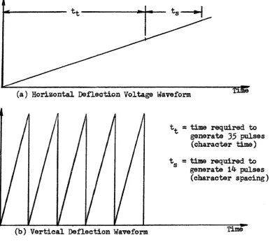
(a) H o rizo n ta l D e f le c t io n V oltage Waveform
t^ = tim e req u ired to gen erate 35 p u lse s
(ch a ra cter tim e)
t g = tim e req u ired to gen erate 14 p u lse s (ch a r a c ter sp a cin g )
Time (b ) V e r t ic a l D e fle c tio n Waveform
( c ) P u lse Train Required to Form the Character 'A'
©
• •
(d ) C haracter Which R e su lts From Combined Waveforms
Figure 2 .1 Use o f th e Unique P u lse Train
12
be d isp la y ed would be n ea rly c u t i n h a lf !
I f one were to generate a 7 x 9 d o t m atrix a t a h igh er speed, th e
c o s t o f th e lo g i c c i r c u i t r y would be in c r e a s e d . In a d d itio n to t h i s ,
m odulation o f the Z -a x is ( i n t e n s i t y ) o f th e c . r . t . becomes d i f f i c u l t a t
h ig h fr e q u e n c ie s. Since one w ish es to generate d o ts and n o t smeared
_7
l i n e s , i n t e n s i f i c a t i o n tim es must be much l e s s than 100 n sec (10 s e c
onds) fo r the d e s ir e d ch aracter g en era tin g sp eed . This fa c to r would
n e e d le s s ly add to th e c o s t o f th e d is p la y c . r . t .
2 .2 The Unique P u lse Train
As th e 35 p o s itio n s o f th e 5 x ? m atrix are b ein g generated sequen
t i a l l y w ith tim e, in form ation must be fe d to th e c . r . t . i n t e n s i f i c a t i o n
c i r c u i t s t o determ ine whether a p a r tic u la r d o t i s to be i n t e n s i f i e d or
n o t. F ig . 2 .1 i l l u s t r a t e s t h i s fo r th e sim ple ca se o f a h o r iz o n ta l and
v e r t i c a l sweep r a s t e r . As th e r a s t e r i s b ein g generated s e q u e n tia lly
i n tim e, the unique p u lse t r a in fo r th e l e t t e r A i s being su p p lied to
th e Z a x i s . The r e s u lt in g ch a ra cter i s shown i n F ig . 2 . I d . Thus some
method o f gen era tin g a unique p u lse t r a in i s req u ired fo r a l l p r in tin g
characters bein g generated by th e d is p la y . This w i l l be d isc u sse d i n
the remainder o f t h i s ch ap ter.
2 .3 General D e sc r ip tio n o f the C haracter Dot Generator
The a c tu a l gen era tio n o f th e unique p u lse t r a in s fo r each ch aracter
i s common to a l l th re e ch aracter generators which are d isc u sse d i n the
remainder o f t h i s t h e s i s . Only th e c o n tr o l u n it and the r a s te r generator
vary i n th e th ree system s and one s l i g h t m o d ific a tio n must be made to a
cou n ter.
The ch aracter d o t generator i t s e l f c o n s is t s o f a c lo c k , a s i x b i t
p ro d u c e d w ith p e rm is sio n of the c o p y ri g h t o w n e r. F u rth e r re p ro d u c tio n p ro h ib ite d w ith o u t pe rm is s io n .
SPECIAL
CONTROL CHARACTER€>,
P CHARACTER
BUFFER
UNIT DECODER DECODER PARALLEL DATA CHANNEL PULSE COUNTER SELECTION DECODER GATESz - S f r s
TO HORIZONTAL AND VERTICAL RASTER TIMING DELAY
CLOCK COUNTER
14-co u n ter, a 14-counter d e14-cod er, g a tin g c i r c u i t r y to s e l e c t unique p u lse tr a in s
fo r each character and a b u ffe r to h o ld th e ASCII code o f th e ch a ra cter
whose p u lse t r a in i s to be g ated to th e Z -a x is . In a d d itio n , an i n h i b i t
g a te i s used to p rev en t th e p u lse t r a in from reachin g th e Z -a x is i n sp e
c i a l c a s e s . A b lo ck diagram o f th e ch a ra cter d o t gen erator i s g iv e n i n
P ig . 2 . 2 .
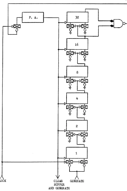
2 .4 The Counter
A s i x b i t b in a ry up co u n ter which i s capable o f cou n tin g up to
2^ = 6 4 i s u sed . T h ir ty -F iv e counts correspond to th e 35 d o ts i n the
5 x 7 m a trix . However, space must be in s e r t e d between c h a r a c te r s.
I f a sweep c i r c u i t i s used to provide th e h o r iz o n ta l d e f le c t io n ,
th e beam i s moving a t a c o n sta n t r a t e . To provide two h o r iz o n ta l r a s t e r
u n it s (d o t p o s it io n s ) o f sp a cin g between c h a r a c te r s, enough tim e must
pass to provide f o r an a d d itio n a l 14 d o ts ( i . e . two columns o f 7 d ots
e a c h ). Hence 49 c lo c k p u lse s must be counted. This type o f coun ter i s
used by the r a s t e r g en era to rs which w i l l be d is c u s se d i n Chapter H I .
I f th e h o r iz o n ta l beam p o s it io n i s produced by a b in ary cou n ter and
a D/A co n v e rter , o n ly one a d d itio n a l p u lse a f t e r th e 35 m atrix counts
w i l l be req uired to provide th e s p a c e . This w i l l be d is c u s se d i n d e t a i l
i n Chapter IV.
A NAND gate d e t e c t s a coun ter v a lu e o f 35 fo r th e D/A co n v erter
method or a count o f 48 fo r th e h o r iz o n ta l sweep method. The outpu t o f
t h i s gate en a b les th e DCD g a te o f a p u lse a m p lifie r . Thus th e 36th or
th e 49th c lo c k p u lse p a sse s through th e p u lse a m p lifie r . This p u lse i s
used to c le a r th e co u n ter , th e b u ffe r and th e "GENERATE" f l i p - f l o p which
i s a d ev ice busy f l a g i n th e c o n tr o l u n i t . When t h i s f l i p - f l o p i s s e t ,
CLOCK GENERATE BUFFER
AND GENERATE
Figure 2 .3 C ou n ter.for H orizontal Sweep Method
e p ro d u ce d w ith p e rm is sio n of the c o p y ri g h t o w n e r. F u rth e r re p ro d u c tio n p ro h ib ite d w it h o u t per m is s io n .
CLEAR A/N BUFFER, GENERATE SPACE, CHARACTER COMPLETE
GENERATE
CLOCK
i t en a b les th e cou nter; c le a r in g i t d is a b le s th e c o u n ter . The 36th c lo c k
p u lse a ls o g en era tes th e c h a ra cter space i n th e c a se o f th e d /a co n v erter
method. P ig . 2 .3 i l l u s t r a t e s the cou nter which would be used w ith a
h o r iz o n ta l sweep c i r c u i t . I t i s capable o f o p e r a tin g a t a c lo c k frequency
o f 1 .0 8 MHz.
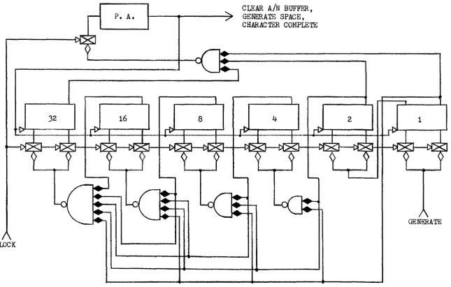
One s e r io u s problem which arose from u sin g DEC 2 me modules was
t h a t each f l i p - f l o p has a nom inal ca rry prop agation o f 70 n s e c . This
means th a t one must w a it fo r up to 420 n sec fo r th e cou n ter to reach a
ste a d y s t a t e . But a t 2 MHz, the c lo c k p u ls e s are 500 n sec a p a rt. Hence
o n ly 80 n sec i s a v a ila b le during which i n t e n s i f i c a t i o n w ith i t s a s s o c i
a ted g a tin g propagation d e la y s can take p la c e . This i s i n s u f f i c i e n t .
To e lim in a te ca rry tim e a DC ca rry ch a in was u se d . This perm its
th e c o n str u c tio n o f a cou n ter o f any s i z e w ith a l l f l i p - f l o p s sw itch in g
sim u lta n e o u sly . I t c o n s is t s o f s i x in tercon n ected , diod e g a te s w ith tw o,
t h r e e , . . . , s e v e n in p u ts each o f which has an ou tp u t o n ly when the in p u t
to t h a t gate and t o a l l th e g a te s o f l e s s e r s ig n if i c a n c e are i n th e one
s t a t e ( i . e . a ca rry w i l l occu r on th e n e x t c o u n t). I n t h i s way th e i n
put DCD g a tes o f th e f l i p - f l o p s through which a ca rry would propagate
are en a b led . Sin ce th e c lo c k i s fe d to a l l f l i p - f l o p s i n p a r a l l e l , th ose
w ith enabled DCD g a te s w i l l be complimented sim u lta n e o u sly . Hence no
propagation d e la y w i l l occur fo r a c a rr y . F ig . 2 . 4 i l l u s t r a t e s a 2 MHz
cou n ter which would be used fo r th e d/a c o n v erter method.
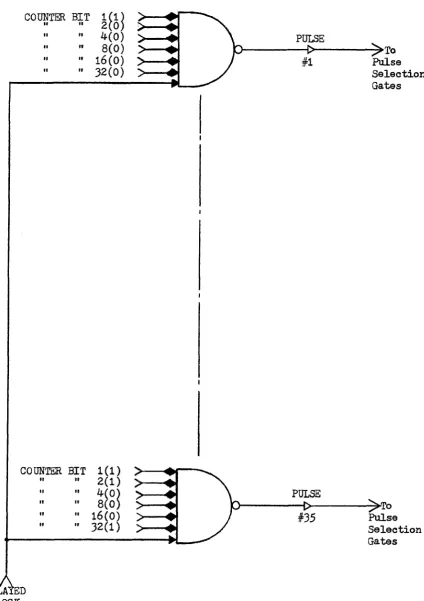
2 .5 The Counter Decoder
A sequence o f 35 p u lse s i s req u ired to i n t e n s i f y each d o t o f the
5 x 7 m a trix . A s e r i e s o f 35# 7 -in p u t NAND g a te s i s u sed i n the counter
decod er. S ix o f th e in p u ts are connected to th e outpu ts o f th e s i x
18
COUNTER BIT 1
HO)
8(0) 16( 0 ) 3 2 ( 0 )
PULSE
;>To Pulse S e le c t io n Gates
COUNTER BIT 1 (1 ) " 2 (1 )
PULSE
^>To Pulse S e le c t io n Gates 16(0 )
3 2 (1 ) #35
DELATED CLOCK
Figure 2 .5 The Counter Decoder
7 # 1 4 # 21 # 2 8 # 3 5 #
6 9 1 3 9 2 0 # 2 7# 3 4 #
5 # 1 2 # 1 9 # 2 6 # 3 3 #
4 # 1 1 # 1 8 # 2 5 # 3 2 #
3 # 10 # 1 7 # 2 4 # 3 1 #
2 # 9 # 1 6 # 2 3 # 3 0 #
1 # 8 # 1 5 # 2 2 # 2 9 #
(a ) The B a sie 5 x 7 Dot Matrix
PULSE NUMBER 1
A1 S e le c t io n Gate 24
PULSE NUMBER 4
12
'<—* Selec-jC t i o n Gate / 20
Figure 2 .6 b The Pu lse S e le c t io n Gates
To *A'
_► ^
C haracter Decoder Gate
To
-* >
C haracter Decoder Gate
20
f l i p - f l o p s o f th e co u n ter i n such a way th a t the f i r s t g a te d e t e c t s a
count o f one, th e secon d a count o f two, up to th e t h i r t y - f i f t h which
d e te c ts a count o f 35*
The sev en th in p u t to each o f th e g a tes i s a d ela y ed c lo c k p u ls e .
R efer to f i g . 2 .5 » The c lo c k must be d elayed because th e c lo c k p u lse s
are f i r s t used to change th e co u n ter . A fte r the cou nter i s changed by
the c lo c k p u lse and th e 35 g a te s have reached a s te a d y s t a t e c o n d itio n ,
the delayed c lo c k p u lse reaches th e g a t e s . This p rev en ts the am biguity
which cou ld occur i f th e 35 decoder g a te s were sampled a t th e same time
the counter was changing.
Thus each NAND g a te w i l l have an ou tp u t when i t s p a r tic u la r count
i s p resen t i n th e c o u n te r . S in ce o n ly one gate can be enabled a t any
one tim e, th e g a te s provide 35 d i s t i n c t p u lse s which are s e q u e n tia l i n
tim e.
2 .6 P ulse S e le c t io n Gates
Each ch a r a cter which i s to be generated i s composed o f unique d o ts
s e le c t e d from the b a s ic 5 x 7 m atrix which i s shown i n f i g . 2 .6 a . As
the va rio u s d o t p o s it io n s are generated by th e r a s t e r g en erator (sweep
or d/a c o n v e r te r ), a d e c is io n as to whether to i n t e n s i f y a d o t or n o t
must be made f o r each p a r tic u la r c h a r a c te r . This i s done by th e p u lse
s e l e c t i o n NAND g a t e s .
The in p u ts to th e s e g a te s are the outputs o f th e counter decoder
NAND g a te s . I f a c h a r a c te r r e q u ir e s d o t #1 o f th e m a trix , the output
o f th e f i r s t cou n ter decoder NAND gate i s u sed . Hence th e p u lse s e l
e c t io n gate fo r a p a r t ic u la r ch a ra cter w i l l have as many in p u ts as th ere
are d o ts i n th e com pleted c h a r a c te r . S in ce th e in p u ts were ou tp uts o f
■p G ci)
-P O
W *H -P «) *H -H
® -H oq
^
6
)•rl CO
G\
CO =#s
o =#= ■p ■H =s=
a fr, p &S
O 00 '
Reproduced with permission of the copyright owner. Further reproduction prohibited without permission.
F
ig
u
re
2.
7
Th
e
Bu
ffe
r
R
e
g
is
te
22
the preceding counter decoder NAND g a te s the fo llo w in g Boolean e x p r e ss
io n w i l l be true i f p u lse s 8 f 9 , 15» 16 were to be u s e d
:-PULSE TRAIN = :-PULSE #8 A :-PULSE #9 A :-PULSE #15 A :-PULSE #16
= PULSE #8 V PULSE #9 V PULSE #15 V PULSE #16
Thus we s e e th a t th e p u lse s e l e c t o r NAND g a te s a c t as OR g a t e s . The
output o f th ese g a te s w i l l be a unique p u lse t r a in fo r each ch a ra cter
to be generated.
At p resen t a s i x t y ch a r a cter s e t o f "printing" ch a ra cters i s used
bu t t h i s could be expanded to any s i z e by the a d d itio n o f more p u lse
s e l e c t o r NAND g a te s . A l i s t o f a l l the p u lse s req u ired to form each
ch a ra cter and a model o f each ch a ra cter can be found i n Appendix I I .
Samples o f th e g a tes are shown i n F ig . 2 .6 b .
2 .7 The B uffer R e g is te r
This r e g is t e r h o ld s th e ASCII code fo r th e ch a ra cter which i s cur
r e n t ly b eing gen erated . Although th e ASCII code r eq u ir es 8 b i t s to d e fin e
th e f u l l ch aracter s e t , n o t a l l b i t s need be u t i l i z e d . I f one o n ly w ish es
to generate the p r in tin g c h a r a cter s o f the ASR 33 T elety p e , th e s i x l e a s t
s i g n i f i c a n t b i t s o f th e code would be s u f f i c i e n t s in c e 2^ = 64 ch a ra cters
could be s e le c t e d .
I n our c a se , seven b i t s were used so th a t n o n -p rin tin g o p era tio n s
such as l i n e fe e d , c a r r ia g e r e tu r n , ta b u la te and back space co u ld be d e
r iv e d d i r e c t l y from th e t e le t y p e keyboard. This a ls o provid es f o r ex
pansion o f up to 2? = 128 c h a r a c te r s. A com plete l i s t o f th e ASCII codes
used w i l l be found i n Appendix I .
The b u ffe r which h o ld s th e ASCII code c o n s is t s o f seven f l i p - f l o p s
which can be loaded i n p a r a l l e l . The c o n tr o l o f th e lo a d in g o p era tio n
BUFFER BIT 7(1
" 2 (0 ) OUTPUT OF 'A' SELECTION GATE
A cts As An 'OR'
Gate o f C.R.T
BUFFER BIT 7(1
" 2( 1 ) OUTPUT OF V-' SELECTION GATE
Figure 2 .8 The C haracter Decoder
2k
would be by computer or by a s p e c ia l c o n tr o l u n i t . This w i l l be d i s
cussed fu rth er i n the fo llo w in g c h a p te r s. The d is p la y b u ffe r r e g is t e r
(DBR) could be the accumulator o f th e computer o r th e memory b u ffe r
r e g is t e r o f a r e fr e s h memory. F ig . 2 .7 shows th e b u ffe r in p u ts as be
in g the seven l e a s t s i g n i f i c a n t b i t s o f th e r e fr e s h b u ffe r which w i l l
be described, b r i e f l y i n chapter V I.
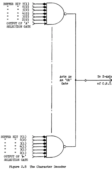
2 .8 The Character Decoder
The reader has probably noted t h a t th e unique p u lse t r a in fo r ev
e r y ch aracter was generated sim u lta n eo u sly by th e P ulse S e le c t io n G ates.
Some means o f s e l e c t i n g o n ly th e ch a ra cter p u lse t r a in whose ASCII code
i s contain ed i n the b u ffe r must be p rovid ed . This s e l e c t i o n i s per
formed by th e character decoder.
At p r e se n t, s i x t y p r in tin g ch a ra cters are generated and th ey o n ly
req u ire s i x b a ts o f the b u ffe r to d e fin e them u n iq u e ly . Thus th e se v
en th b i t i s n o t needed a t t h i s p o in t and w i l l be d is c u s se d fu r th e r i n
th e chapter on S p e c ia l C h aracters.
The ch a ra cter decoder i s comprised o f a s e t o f s i x t y 7 -in p u t NAND
g a tes w ith a g a te corresponding to each c h a r a c te r . The f a c t th a t o n ly
s i x b i t s d e fin e the s i x t y ch a ra cters provid es a s u b s t a n t ia l sa v in g s in
hardware s in c e one l e s s in p u t i s needed fo r each gate (an 8 -in p u t NAND
gate would have been req u ired i f a l l seven b u ffe r b i t s were u s e d ). S ix
o f th e in p u ts are fe d by th e output o f the s i x l e a s t s i g n i f i c a n t b u ffer
f l i p - f l o p s . Each decodes a d if f e r e n t ASCII c o d e. The sev en th in p u t i s
fe d by the ou tp ut o f th e P u lse S e le c t io n gate which g en era tes th e p u lse
t r a in fo r th e ch aracter s p e c if ie d by th e ASCII code on th e o th er s i x
in p u ts . The ch aracter decoder i s i l l u s t r a t e d i n F ig . 2 . 8 . The fo llo w
in g Boolean e x p r e s s io n a p p l i e s
DECODER OUTPUT = PULSE TRAIN A ASCII CODE
or DECODER OUTPUT = PULSE TRAIN A ASCII CODE
Hence th e ch a ra cter decoder a c ts as an AND g a te .
The ou tp u ts o f th e s i x t y ch a r a cter decoder g a tes must be 'OR'ed t o
gether and then fe d to the i n t e n s i f i c a t i o n c i r c u i t r y . This would r e
q u ire a s i x t y in p u t 'OR' gate which o b v io u s ly exceeds the f a n -in cap
a b i l i t i e s o f DEC 2 MHa c i r c u i t s . N o tic e , however, th a t o n ly one char
a c te r decoder g ate can be a c t iv e a t one tim e ( i . e . t h e ir ou tp uts are
e x c l u s i v e ) . By sim p ly w ir in g -toe ou tp u ts o f th e s i x t y decoder g a te s
to g e th er w ith a s in g le clamped lo a d we are ab le to perform th e 'OR'
o p era tio n and. n o t u se any l o g i c a l hardware. In f a c t , we have fr e e d
59 clamped lo a d s which cou ld be u sed e lse w h e r e . F ig . 2 .8 g iv e s th e l o
g ic diagram o f th e ch a r a cter d ecoder.
TWO METHODS OF BEAM POSITIONING USING AN ANALOGUE HORIZONTAL SWEEP
3*1 In tro d u ctio n
In 1968* a p r o j e c t was begun by t h i s department which has now
brought us c lo s e to th e com pletion o f a complete grap hics te r m in a l.
This w i l l be d is c u s se d fu r th e r i n chapter VI.
O r ig in a lly i t was d ecid ed th a t a sim p le, lo w -c o s t ch a ra cter gener
a to r should be c o n str u c ted which used a r a s t e r sweep method. At th a t
tim e , the method o f unique p u lse g en era tio n which was d e scr ib e d i n chap
t e r I I was d evelop ed . A t e s t model was co n stru cted to dem onstrate the
f e a s i b i l i t y o f th e method. I t was th en decided to in co rp o ra te th e char
a c te r generator in t o a la r g e r , more s o p h is t ic a te d system .
During th e subsequent developm ent, th ree methods o f r a s t e r genera
t i o n have been t e s t e d . A ll u t i l i z e th e same method o f s e l e c t i n g the
ch aracter p u lse t r a in s d e scr ib e d i n th e preceding ch a p ter . Each method
arose as th e p r o je c t proceeded toward a goal o f in c r e a se d speed and f l e x
i b i l i t y .
The two methods o f beam p o s it io n in g which use a h o r iz o n ta l sweep
c i r c u i t w i l l be d e scr ib e d i n the remainder o f t h i s ch a p ter.
3 .2 H orizo n ta l and V e r t ic a l Sweep Method
8
In 1968-69, another M aster's c a n d ita te d esign ed and constructed,
a lim ited, t e s t model o f an A/N ch a ra cter generator which s u c c e s s f u lly
generated the l e t t e r s "A" and "C”.
26
• f
• •
• •
j : ;i ' ; f i
4
I
*
4
# •
*
m
$
fig u r e
out-put 0f Orig1' .nal
CPataoter
Generatorp epf°du
oedwWP
6'""55'00
o U t e copvrtX"0'""6''
proW'tofted
0"-28
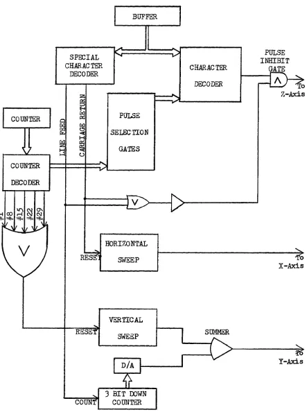
His method o f g en era tin g th e v e r t i c a l sweep was to u t i l i z e th e saw
to o th output o f a TEKTRONIX typ e 5^5 o s c illo s c o p e tr ig g e r e d by p u lse s l f
8 , 1 5 , 22 and. 29 which were d e r iv ed from th e cou nter d ecoder. This pro
duced f iv e lin e a r sweeps which were fe d to the Y -a x is o f a TEKTRONIX
typ e 56^ sto r a g e o s c i l l o s c o p e .
To provide a h o r iz o n ta l sweep, he used an in t e g r a te and. h o ld c i r
c u i t which charged a c a p a c ito r a t a uniform r a te during th e a c tu a l gen
e r a t io n o f th e c h a r a c te r . The f i n a l v o lta g e was h e ld u n t i l th e n e x t
ch a ra cter was generated and th e c a p a c ito r would, a g a in be charged to a
h ig h er v o lt a g e . The output o f t h i s in t e g r a to r was fe d to th e X -a x is o f
th e sto ra g e o s c il lo s c o p e .
When th e ou tp ut o f th e c h a r a cter decoder *0R' g a te was fe d to th e
Z -a x is o f th e sto r a g e o s c i l l o s c o p e , ch a ra cters cou ld be g en erated as
shown i n T ig . 3«1»
While t h i s method worked, i t was s e v e r e ly lim it e d i n speed by th e
in t e g r a te and h old c i r c u i t . Due to th e la r g e c a p a c ito r which was u sed ,
more than 100 msec were req u ired to d isch arge i t . This meant t h a t ,
w h ile a l i n e cou ld be w r itte n a t a f a i r l y h igh ch a ra cter sp eed , a f u l l
te n th o f a second was req u ired b efo re th e n ex t l i n e cou ld be w r it t e n .
For a low c o s t ch a ra cter gen erator u t i l i z i n g a sto r a g e c . r . t . th e
above r a s te r g en era tin g tech n iq u e would be s u f f i c i e n t . I f a normal
telep h o n e channel capable o f tr a n s m ittin g 1 ,2 0 0 b i t s / s e c . were used to
provide th e ASCII codes to th e ch a ra cter g en era to r, t h i s method would
be i d e a l .
Of co u rse, much f a s t e r sweep c i r c u i t s can be c o n stru cted as can
in t e g r a t e and h old c i r c u i t s . S in ce th e v e r t i c a l sweep c i r c u i t must on
l y sweep o u t a s in g le ch a ra cter h e ig h t , i t could be r e l a t i v e l y n o n -lin e a r
BUFFER
PULSE INHIBIT
GATE
Z-Axis SPECIAL
CHARACTER
DECODER CHARACTER
DECODER
PULSE COUNTER
C£
GATES
COUNTER
DECODER
o\
pH CO rH - - .
—«,i —m —i» —u - t »
=;^5: =f?=:
HORIZONTAL
:ES; SWEEP
X-Axis
VERTICAL
RESET* SUMMER
SWEEP
Y-Axis d/a
3 BIT DOWN COUNTER COUNT*
Figure 3*2 C haracter Generator With H o rizo n ta l and V e r tic a l Sweep