Performance Comparison of Non-Contact and
Contact Feeding Technique for Rhombus
Shaped Microstrip Antenna
Madhusudhana K1, Dr.Jagadeesha S2
Assistant Professor, Dept. of ECE., SDMIT, UJIRE, Karnataka, India1
Professor, Dept. of ECE., SDMIT, UJIRE, Karnataka, India2
ABSTRACT: Microstrip patch antennas are fed by different feeding techniques. These feeding techniques can be classified into two categories- contacting and non-contacting. In this paper, weare present a comparative analysis between two different feeding techniques belonging to two different categoriesthat are used for Rhombus shaped Microstrip antenna. The feeding techniques used are Microstrip line feeding technique (contacting feeding technique) and proximity coupled feeding technique (non-contacting feeding technique). Through comparison, it is found that proximity coupled feeding technique will give a good bandwidth of 73.64MHz with again of 1.112dBi. The Simulation is carried out using IE3D software and practical results are measured with Vector Network analyzer(VNA). Practical results are agreement with the simulated results.
KEYWORDS: Rhombus shaped Microstrip Antenna, feeding technique, Microstrip line and Proximity coupled.
I. INTRODUCTION
Microstrip antennas [1] are one of the most rapidly developing fields in last twenty years. Nowadays, these antennas have variedapplication [4] and play an important role in mobile radio systems, integrated antennas, satellite navigation receivers, satellite communications [12], direct broadcast radio, television etc. Interest in microstrip antennas [6] has peaked,due to their considerable advantageover conventional microwave antennas such as beinglightweight [2], consumption of low volume, conformability, low price compactness[7]and ease of manufacture. Despite of all this, microstrip antennas are weighed down when it comes to their limited bandwidth [3].
There are different feeding techniques which are used to feed microstrip antennas.Rhombus shaped microstrip antenna can be fed through contact and non-contact feeding [5].In this paper we are going to present a comparison between two feeding techniques belonging to two different categories, proximity coupled [8]and microstrip line feed technique [9-10], for Rhombus shaped microstrip antenna.In contact method [11], RF power is fed directly to the radiating patch, using a SMA connector. In non-contact scheme, electromagnetic field coupling is done to transfer power between radiating patch and microstrip line feeding.
II. ANTENNADESIGN
Rhombus shaped microstrip patch antenna is designed for three essential parameters, which are as follows: I. Frequency of operation (f0): Resonant frequency of the designed antenna is 2.58GHz.
II.Dielectric constant of the substrate (εr): The dielectric material selected for design purpose is glass epoxy, which has
a dielectric constant of 4.4.
III.Height of dielectric substrate (h): As microstrip patch antenna should not be bulky, height of the dielectric substrate is selected as 1.6mm.
Radiating patch of Rhombus shaped Microstrip Antenna is designed using following formulae.
λo =
Width of patch W= (Ɛ ) /
Length of Patch L = −2∆L
Effective length ∆L = 0.412h∗( . ) .
( . ) .
Where ε = + [1 + 12 ]
Substituting in above shown equations, we get W=35.38mm and L =27.34mm. Optimized resonating frequency of the designed antenna which is operating at 2.58GHz for that we are considered length and width of a radiating patch is 27mm.
The proposed rhombic shaped microstrip antenna with proximity couple feeding is shown in Fig.1. The Rhombus shaped microstrip antenna whose radiating patch size is 27mm x 27mm is printed on a dielectric substrate S1 of thickness 1.6mm. The Substrate material used is glass epoxy with dielectric permittivity of εr=4.4, which is designed to
operate at 2.58GHz.
Fig 1: Geometry of Rhombus shaped Proximity couple antenna
The optimized designed dimension of designed antenna are as follows:h1=1.6mm,L=27mm, W=27mm, Lf=18mm,
Wf=3mm and h2=1.6mm.With a ground plane of dimension (54 x 58) mm2, the feeding patch is placed between two
substrates and it is connected through SMA connector. The Photograph of top and bottom viewof practical Rhombus shaped microstrip antenna with proximity coupled feed shown in Fig.2.
The proposed rhombic shaped microstrip antenna with microstrip line feeding is shown in Fig.3.The Rhombus shaped microstrip antenna whose radiating patch size of 27mm x 27mm is printed on a dielectric substrate of thickness 1.6mm. The Substrate material used is glass epoxy with dielectric permittivity of εr=4.4, which is designed to operate at
2.58GHz.
Fig 3: Geometry of Rhombus shaped microstrip line feeding antenna
The optimized designed dimension of a rhombus shaped MSA antenna using microstrip feed technique are as follows: h=1.6mm, L=27mm, W=27mm, Lt=15.4mm andWt=0.3mm, Lf=15.4mm, Wf=3mmthey are mounted on a
ground plane of dimension (78.45 x 57.4) mm2.The antenna with feeding patch is connected through SMA connector.The Photograph of top and bottom view of practical Rhombus shaped microstrip antenna with microstrip line feed is shown inFig.4.
.
III.EXPERIMENTALRESULTS
The return loss characterization of simulated and practical rhombus shaped microstrip antenna (RMSA) with proximity coupled feeding shown in Fig 5, the return loss and bandwidth values are summarized in table 1.
Fig 5.Variation of return loss versus frequency of rhombus shaped Proximity coupled MSA.
The Fig 6 shows the performance gain characteristic of rhombus shaped microstrip antenna (RMSA) with proximity coupled feeding, with a maximum gain of 1.112dBi at resonant frequency.
The radiation pattern and current distribution of rhombus shaped microstrip antenna (RMSA) with proximity coupled feeding as show in Fig 7 and Fig 8.
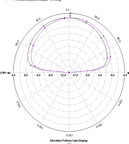
Fig 7.Radiation pattern of rhombus shaped Proximity coupled MSA
Fig 8.Current distribution of rhombus shaped Proximity coupled MSA
Fig 9. Variation of return loss versus frequency of rhombus shaped microstrip line feed MSA.
The radiation pattern and current distribution of rhombus shaped microstrip antenna (RMSA) with microstrip line feeding as show in Fig 11 and Fig 12.
Fig 11.Radiation pattern of rhombus shaped microstrip line feed MSA
Fig 12. Current distribution of rhombus shaped microstrip line feed MSA
Table 1: Performance comparison of the proposed antennas SL No Prototype Antenna Resonant Frequency
fr (GHz)
Return Loss (dB)
Bandwidth (MHz)
Impedance
(Ω) Gain
(dBi) Simul. Pract. Simul. Pract. Simul. Pract. Simul. Pract.
1
Rhombus shaped microstrip antenna with Proximity coupled feeding
2.588 2.576 -13.25 -15 116.21 73.64 43 54 1.112
2 Rhombus shaped microstrip antenna with microstrip line feeding
The prototype of Non-contact and contact feeding technique for RMSA are measured by Vector Network Analyzer (VNA) as shown in Fig.13.
Fig 13. Vector Network Analyzer
IV.CONCLUSION
Rhombus shaped microstrip antenna(RMSA) with proximity coupled feeding technique will give a good bandwidth of 73.64MHzwith acceptable gain of 1.112dBiin comparison with rhombus shaped microstrip antenna(RMSA) with microstrip line feeding technique which givesan equivalent bandwidth of 60MHz and the corresponding gain of 0.68dBi.To summarize, there is a substantial increase in bandwidth by 13.64MHz and gain by 0.432 dBi as compared to rhombus shaped microstrip antenna(RMSA) with microstrip line feeding technique. The simulation results obtained aregood agreement with experimental results.
REFERENCES
1. H. Wang, X. B. Huang, D. G. Fang, and G. B. Han, ”A Microstrip Antenna Array Formed by Microstrip LineFed Tooth-Like-Slot Patches”, IEEE Transactions on antennas and propagation, vol 55,no 4,April 2007.
2. K.A. Balanis,”Antenna Theory Analysis and Design”, 2nd Edition, John Wiley and Sons,Inc.,1997.
3. David m.Pozar and Susanne M.Voda,,”A RigorourAnalysis of a Microstrip line fed patch antenna” , IEEE Transaction on Antenna and Propogation , vol.35, no.12, ,pp. 1343-1350
4. Kai Fong Lee and Wei Chen, “Advances in Microstrip and Printed Antennas”, John Wiley, 1997.
5. Amit Kumar, JaspreetKaur and Rajinder Singh, “Performance analysis of different feeding techniques”, International Journal of Emerging Technology and Advanced Engineering”, Vol. 3, Issue 3, PP.884-890, March 2013.
6. M.S. Alam, M.T. Islam and N. Misran “Design Analysis of an Electromagnetic Band Gap Microstrip Antenna”, American Journal of Applied Sciences 8 (12): pp 1374-1377, 2011.
7. Savita M Shaka, Prashant R T, Vani R M and P. V. Hunagund,”Enhanced Bandwidth of Rectangular Microstrip Antenna using Uniplanar EBG Cells”, International Journal of Innovative Research in Computer and Communication Engineering, Vol. 2, Issue 4, April 2014.
8. D. M. Pozar and B. Kaufman, “Increasing the bandwidth of a microstrip antenna by proximity coupling,” Electron.Lett., vol. 23, no. 8, pp.368–369, Apr. 1987.
9. Shubham Gupta, ShilpaSingh,”Bandwidth Enhancement in multilayer microstrip proximity coupled array”IJECSE,vol.1,no.2, pp 287-293.
10. Mahesh C P and P M Hadalgi, “Enhanced Bandwidth Proximity Coupled Equilateral Triangular Microstrip Antenna Loaded with Horizontal Rectangular Ring Slot”, International Journal of Innovative Research in Computer and Communication Engineering, Vol. 3, Issue 8, August 2015
11. Hemant Kumar Varshney, Mukesh Kumar, A.K.Jaiswal, RohiniSaxena and Komal Jaiswal, “A Survey on Different Feeding Techniques of Rectangular Microstrip Patch Antenna”, International Journal of Current Engineering and Technology, Vol.4, No.3, June 2014.
12. Madhuri B. Deokate and S. B. Deosarkar, “Compare Proximity Feeding Technique with Probe Feeding for Simple Rectangular Microstrip Antenna”, International Journal of Engineering Research & Technology (IJERT), Vol. 3 Issue 5, May – 2014.
BIOGRAPHY
Madhusudhana Khasreceived his B.E. degree in Electronics and Communication from VTU, Belgaum and M.E. in Power Electronics from UVCE, Bangalore. His research interest in Microstrip Antenna design. Currently working as anAssistant Professor in Dept. of ECE., SDMIT, UJIRE, Karnataka.