INSTALLATION GUIDE
NEC America, Inc.
NDA-30080
Revision 1.0
September, 1998
NEC America reserves the right to change the specifications, functions, or features in this document at any time without notice. NEC America has prepared this document for use by its employees and customers. The information contained herein is the property of NEC America and shall not be reproduced without prior written approval from NEC America.
Copyright 1998
TABLE OF CONTENTS
Page
Chapter 1 - Introduction . . . 1
Overview . . . 1
Chapter 2 - Sentry Alarm Control Terminal . . . 3
Overview . . . 3
Software Installation . . . 5
UNIX Subsystem Database Update. . . 12
Database Creation . . . 13
Sentry Master Database . . . 14
Feature Application Database . . . 14
Window Configuration Files . . . 15
Configuration Parameters . . . 16
Master Configuration File . . . 16
Data Buffer Configuration File . . . 17
Initialization Configuration File . . . 21
Screen Saver Configuration File . . . 22
Function Keys Configuration File . . . 23
Dialogs Configuration File . . . 25
Windows Configuration Files . . . 27
Chapter 3 - Annoyance Trap . . . 31
Overview . . . 31
Additional Manuals . . . 31
Software Installation . . . 32
Configuration. . . 40
Application Characteristics. . . 40
Primary Configuration Parameters. . . 41
OAI Facilities . . . 42
Secondary OAI Configuration Parameters. . . 43
User-Defined Parameters . . . . 44
Database Requirements . . . 45
Database Creation . . . 45
Database Records . . . 45
Building Database . . . 46
Tenant Number Database . . . 47
Chapter 4 - Emergency Conference . . . 49
Overview . . . 49
Additional Manuals . . . 50
Software Installation . . . 50
Configuration. . . 61
Application Characteristics. . . 61
Primary Configuration Parameters. . . 62
OAI Facilities . . . 63
Secondary OAI Configuration Parameters. . . 63
User-Defined Parameters . . . . 64
Page
Database Creation . . . 66
Database Records . . . 66
Sentry Database . . . 67
Conference Card Database . . . 70
Tenant Number Database . . . 71
Building Database . . . 72
Contacts Database . . . 73
Authorized Caller Database . . . . 74
Chapter 5 - Executive Override . . . 75
Overview . . . 75
Executive Override. . . 75
Override Security . . . 76
Installation and Configuration . . . 76
Additional Manuals. . . 77
Software Installation . . . 78
Configuration . . . 87
Application Characteristics. . . 87
Primary Configuration Parameters. . . 88
OAI Facilities . . . 89
Secondary OAI Configuration Parameters. . . 90
User-Defined Parameters . . . . 91
Database Requirements . . . 92
Database Creation . . . 92
Database Records . . . 92
Authorization Code Database . . . 93
Special Station Database. . . 94
Tenant Number Database . . . 95
Executive Override Configuration Sample . . . 96
Chapter 6 - MAT Assignments and PBX Information. . . 99
PBX Software . . . 99
MAT Assignments. . . 99
Executive Override. . . 99
Annoyance Trap. . . 102
Emergency Conference . . . 102
No Dial Alarm Conferencing . . . 103
Conference Cards. . . 103
PA-CFTB Conference Cards . . . 103
Chapter 7 - Platform Maintenance . . . 105
Logging In . . . 105
Attendant Terminal Maintenance . . . 106
Error Log File Browser . . . 108
UNIX Prompt. . . 108
Page
Printer Configuration Files . . . 109
Printer Count . . . 110
Printer Device Name . . . 110
Printer Device Baud Rate . . . 110
Printer Device Parity . . . 110
Printer Device Data Bits . . . 111
Printer Device Stop Bits . . . 111
Format Configuration Files . . . 112
History Log Count . . . 112
History Log Type . . . 112
History Log Name . . . 113
History Log Message Formats . . . 113
Annoyance Trap Messages . . . 116
Emergency Conference Messages . . . 116
LIST OF FIGURES
Figure Title Page
LIST OF TABLES
Table Title Page
2-1 Sentry Master Database Fields . . . 14
2-2 Feature Application Database Fields . . . 14
3-1 Building Master Database Fields. . . 46
3-2 Building Application Database Fields . . . 46
3-3 Tenant Master Database Fields . . . 47
3-4 Tenant Number Application Database Fields . . . 47
4-1 Sentry Master Database Fields . . . 69
4-2 Sentry Application Database Fields . . . 69
4-3 Conference Card Master Database Fields . . . 70
4-4 Conference Card Application Database Fields . . . 70
4-5 Tenant Master Database Fields . . . 71
4-6 Tenant Number Application Database Fields . . . 71
4-7 Building Master Database Fields. . . 72
4-8 Building Application Database Fields . . . 72
4-9 Contacts Master Database Fields . . . 73
4-10 Contacts Application Database Fields. . . 73
4-11 Authorized Caller Master Database Fields . . . 74
4-12 Authorized Caller Application Database Fields . . . 74
5-1 Executive Override Options. . . 76
5-2 Authorization Code Master Database Fields. . . 93
5-3 Authorization Code Application Database Fields . . . 93
5-4 Special Station Master Database Fields . . . 94
5-5 Special Station Application Database Fields. . . 94
5-6 Tenant Master Database Fields . . . 95
Chapter 1
Introduction
This manual describes the installation, databases, and configuration for the Sentry Alarm Control Terminal and the applications that can be used with the terminal.
Overview
This manual contains the following chapters:
Chapter 1, Introduction - Describes the chapters in this installation guide.
Chapter 2, Sentry Alarm Control Terminal - Provides an overview of Sentry
Alarm Control Terminal and describes the installation, databases and configuration parameters.
Chapter 3, Annoyance Trap - Provides an overview of the Annoyance Trap
application and describes the installation, configuration parameters, and databases.
Chapter 4, Emergency Conference - Provides an overview of the Emergency
Conference application and describes the installation, configuration parameters, and databases.
Chapter 5, Executive Override - Provides an overview of the Executive Override
application and describes the installation, configuration parameters, and databases. Also provides a sample configuration.
Chapter 6, MAT Assignments and PBX Information - Describes the NEAX
Maintenance Administration Terminal (MAT) commands that need to be used for each OAI Monitor application as well as the PBX software and conference cards that you need to run Sentry Alarm Control Terminal
Chapter 7, Platform Maintenance - Describes how to use the platform
maintenance utility to perform administrative tasks, including: activating, deactivating, and resetting terminals.
Appendix A, History Logging - Provides a description of the History Logging
Chapter 2
Sentry Alarm Control Terminal
This chapter describes the databases and configuration parameters for the Sentry Alarm Control Terminal software. For information about using the Sentry Alarm Control Terminal, see the Sentry Alarm Control Terminal User Guide.
Overview
The Sentry Alarm Control Terminal is a versatile UAP operator interface
application that communicates with one or more Sentry OAI Monitor applications (such as the Emergency Conference Monitor or the Annoyance Trap Monitor) using message protocols defined by these applications. Data received from the monitors is displayed in real time.
Multiple instances of the Sentry Alarm Control Terminal may be executed simultaneously from the system console and/or from one or more dumb terminals connected to the UAP via RS-232. The content and format of displayed data is controlled through configuration files, allowing a high degree of customization. Each terminal can use a separate configuration, or configurations can be shared. The Sentry Alarm Control Terminal uses text windows to display information and allows the user to manipulate window text from a keyboard. Special function keys are defined to permit the user to quickly perform needed tasks. System messages are used to inform the user of errors and other status changes. Dialog windows are displayed to show current configuration settings or when the program requires information from the user.
The following features are controlled through the configuration file set:
Window and Dialog Attributes
• Screen position
• Size in rows and columns
• Text colors and attributes (bold, blinking, etc.) • Static text fields
• Dynamic text field formats
Real Time Message Display Attributes
• Message text field formats
• Text colors and attributes (bold, blinking, etc.)
Screen Saver Attributes
• Time out values
• Text colors and attributes (bold, blinking, etc.) • Static text fields
There are several processes included in the Sentry Alarm Control Terminal installation:
• Software Installation - Install software from media and follow prompts. • Database Creation - Build, process, and install databases.
• Window Configuration Files - Create configuration files for terminal windows. • Configuration Parameters- Set configuration parameters.
Software Installation
The Sentry Alarm Control Terminal software must first be loaded from the release media. Remember to use the Applications Manager (APM) Installation Manual if you need further instructions for installing software using the APM.
Note: You will be prompted for several values when you install the software. For more information about these and other parameters, refer to the next section, Configuration Parameters on page 16.
1. To begin the Sentry Alarm Control Terminal software installation, log in to the APM Platform Management Menu by typing apmadm at the UNIX login prompt, then press Enter. The login and password prompts are shown below. If your “apmadm” account requires a password, enter the appropriate password at the subsequent password prompt.
The APM Administration main menu displays.
login: apmadm password:
NEC America APM Administration Wed Jan 31, 1996
APM Platform Release Rel2.0 (Oct 09, 1995)
Main Menu APM
Debug Facilities Halt APM System File Archive
Installation of Applications/Packages Removal of Packages
Start-up APM System
Logout UNIX
Enter Option: []
2. Type i and press Enter to select the Installation of Applications/Packages option. The Installation of Application/Packages screen displays.
3. At the “Enter Package to be installed” prompt, type applications and
press Enter. The “Enter Release Media Device” prompt displays.
Installation of Applications/Packages
Available Packages are:
applications asl mtl tcpip update x25
Enter Package to be installed:
NEC America APM Administration Wed - Jan 31, 1996
NEC America APM Administration Wed Jan 31, 1996
Installation of Applications/Packages
Available Packages are:
applications asl mtl tcpip update x25
Enter Package to be installed: applications
(F)loppy Disk Device (C)artridge Tape Device
Enter Release Media Device:
4. Select the floppy disk device as the installation media by typing f and pressing
Enter.
The following screen displays:
5. Insert the Sentry Alarm Control Terminal diskette into the floppy disk device, and press Enter to continue.
The screen displays files in the application installation. Many files may scroll off the screen, until all of the files from the diskette have been processed. The “Has all release media been loaded” prompt displays.
Installation Procedure
Installing from /dev/fd0
Insert OAI Release Media #1 Enter <Return> to continue:
Has all release media been loaded [y or n] ?
x oai/app/sentryTrm/install/ansi_sat, 1038 bytes, 3 tape blocks x oai/app/sentryTrm/install/Mdefault.cfg, 434 bytes, 1 tape blocks x oai/app/sentryTrm/install/.profile, 1673 bytes, 4 tape blocks
.
x oai/chksum_app, 1011 bytes, 2 tape blocks x oai/app/sentryTrm.ins, 8459 bytes, 17 tape blocks
x oai/app/sentryTrm/bin/sentryTerm, 540414 bytes, 1056 tape blocks
6. Type y and press Enter to indicate that all release media has been loaded. The APM installation begins processing all of the Sentry Alarm Control Terminal installation files and checking them for correctness. The screen indicates the status of the installation.
After the files have been processed, the “root password” prompt displays. In order to complete the Sentry Alarm Control Terminal installation, you must modify certain files that require “root” privileges.
OAI Platform is at revision 5 for machine i386 (Dec 19 1994 Rel 1.6.1)
sentryTrm Revision: 5 machine type: i386 Version: 1.7 Processing, please wait...
Validating installed files ...
Validation Completed
Installing the Release Files
Processing files
Installation requires Super User (root) privileges.
Please Enter su/root Password:
7. Type in the root password at the prompt and press Enter to continue.
The Sentry Alarm Control Terminal installation will create any directory that does not already exist. The paths of the directories will display on the screen, as illustrated below.
8. Press Enter to continue the installation. The sentry user is added to the SCO UNIX operating system.
Creating Sentry Terminal directories . . .
/oai/app/sentry created
NEC America Inc Sentry Terminal Installation Wed - Apr 29, 1998
/oai/app/sentry/bin created /oai/app/sentry/install created /oai/app/sentry/cfg created
/oai/app/sentry/cfg/terminals created /oai/app/sentry/cfg/terminals/default created /oai/log already exists
/oai/log/sentry created
Press Enter to continue. [ ]
Installing sentry user on SCO UNIX.
Enter (sentry) user id [6000]:
NEC America Inc Sentry Terminal Installation Wed - Apr 29, 1998
User (sentry) already belongs to a group.
User (sentry) installed.
9. Press Enter again and the sntryadm user is added to the SCO UNIX operating system.
10. A warning indicating that the user ID has already been assigned to the system displays. Type y and press Enter to install the sntryadm user with the same ID. The sntryadm user is added to the system.
Installing sntryadm user on SCO UNIX.
Enter (sntryadm) user id [6000]:
NEC America Inc Sentry Terminal Installation Wed - Apr 29, 1998
Warning: The user id [6000] is already assigned on this system, Install (sntryadm) with user id [6000] (y/n)
Installing sntryadm user on SCO UNIX.
Enter (sntryadm) user id [6000]:
NEC America Inc Sentry Terminal Installation Wed - Apr 29, 1998
Warning: The user id [6000] is already assigned on this system, Install (sntryadm) with user id [6000] (y/n) y
User (sntryadm) already belongs to a group.
User (sntryadm) installed.
11. Press Enter to continue the installation.
12. Press Enter to continue.
The following screen displays when the installation is complete.
13. Press Enter.
Installing the Sentry Terminal Binary . . .
NEC America Inc Sentry Terminal Installation Wed - Apr 29, 1998
Installing the Sentry Database Files . . .
Installing the Default Terminal Configuration Files . . . Installing the ansi_sat terminal information . . . Installing the Sentry Platform Maintenance Utilities . . . Installing /etc/mygetty . . .
Updating /etc/gettydefs . . .
Press Enter to continue. [ ]
Sentry Terminal Installation Complete.
The following configuration tasks must be completed before NEC America Inc Sentry Terminal Installation Wed - Apr 29, 1998
1. Build, process, and install the sentry_m database. starting Sentry Terminal application
2. Build a window configuration file for each entry in the sentry_m database
See the Sentry Terminal Installation guide for more information.
UNIX Subsystem
Database Update
The SCO UNIX Subsystem database must be updated for the Sentry Alarm Control Terminal.
At the UNIX prompt, login as the superuser (root) and execute the SCO UNIX Subsystem Database authorization checking program (/tcb/bin/authck -s) and password deletion program (passwd -d) as shown below.
Answer yes when asked to fix the subsystem databases. This ensures that the SCO UNIX Subsystem Databases are left in a proper state.
login: root
.
# passwd -d sentry
. . .
Password: <root password> # /tcb/bin/authck -s
The following users have Protected Password Database entries that do not match their Subsystem Database entries:
sentry sntryadm
There are errors in the database. fix them (y/n)> Y <ENTER>
Deleting password for user sentry # passwd -d sntryadm
Database Creation
The Sentry Master Database contains information used by the Emergency Conference, Annoyance Trap, and Sentry Alarm Control Terminal applications. The Feature Application Database contains a sub set of the Sentry Master Database and is used by the Sentry Alarm Control Terminal program. Each feature database record contains an entry for each Sentry feature (Emergency Conference or Annoyance Trap) used by the system. Refer to the APM Configuration Manual for more information.
Each sentry master database record contains the following fields:
Monitored Number
The monitored number used by the caller to access the Emergency Conference or Annoyance Trap.
Category
An ASCII string containing the record category, which is set to “conference” for Emergency Conference records or “annoyance” for Annoyance Trap records.
Name
An ASCII string containing the Emergency Conference or Annoyance Trap name.
Minimum Lines Used
The minimum number of lines required by an Emergency Conference. This field is not used by the Sentry Alarm Control Terminal.
First Line Number
The first line number of the dedicated conference card set used by an Emergency Conference. This field is not used by the Sentry Alarm Control Terminal.
Override Allowed
A simple Y/N character that determines whether or not an emergency conference will override busy destinations. This field is not used by the Sentry Alarm Control Terminal.
Warning Tone Issued
A simple Y/N character that determines whether or not an Emergency Conference will issue a warning tone when a caller joins a conference. This field is not used by the Sentry Alarm Control Terminal.
Window Symbol
The name of the window symbol associated with an Emergency Conference or Annoyance Trap.
Contact Database
The name of the contacts database file used by an Emergency Conference. This field is not used by the Sentry Alarm Control Terminal.
Authorized Database
Sentry Master
Database
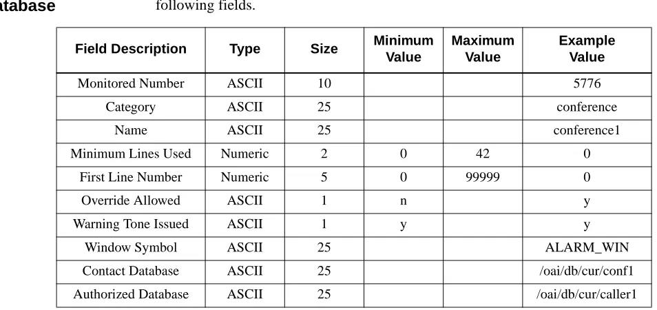
The Sentry master database is named “sentry_m” by default and contains the following fields.
Table 2-1 Sentry Master Database Fields
Feature
Application
Database
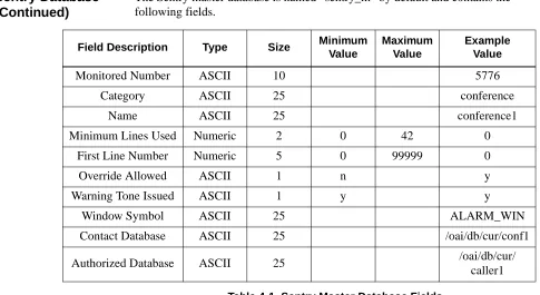
The feature application database uses data contained in the sentry master database. It is called “features” by default and contains the following fields.
Table 2-2 Feature Application Database Fields
Field Description Type Size Minimum
Value
Maximum Value
Example Value
Monitored Number ASCII 10 5776
Category ASCII 25 conference
Name ASCII 25 conference1
Minimum Lines Used Numeric 2 0 42 0
First Line Number Numeric 5 0 99999 0
Override Allowed ASCII 1 n y
Warning Tone Issued ASCII 1 y y
Window Symbol ASCII 25 ALARM_WIN
Contact Database ASCII 25 /oai/db/cur/conf1
Authorized Database ASCII 25 /oai/db/cur/caller1
Field Description Data Type
Monitored Number ASCII
Name ASCII
Window Symbol ASCII
Window Configuration Files
To create window configuration files:
1. Log in as apmadm to access the APM Administration Main Menu. 2. At the APM Administration Main Menu, type U to exit to UNIX. 3. At the UNIX prompt, type the following to change to the Sentry Alarm
Control Terminal default configuration directory:
cd /oai/app/sentry/cfg/terminals/default
4. Make a feature configuration file for each Sentry Feature by copying the “feature.def” file using the following command:
cp feature.def <name.cfg>
where <name.cfg> is a unique name assigned by you. For example,
cp feature.def fire.cfg
5. Use a UNIX editor (such as vi) to edit each feature configuration file, following the instructions contained in the file’s header. For example,
vi fire.cfg
6. After the feature configuration files have been created and edited, use the following command to change to the Sentry Alarm Control Terminal configuration directory:
cd /oai/app/sentry/cfg/terminals
7. Use a UNIX editor (such as vi) to edit the Default Master Configuration file (Mdefault.cfg). Add the full path of each feature configuration file to the list within the Master Configuration file. For example,
vi Mdefault.cfg
Configuration Parameters
The Sentry Alarm Control Terminal application uses configuration parameters defined in configuration files found in the “/oai/app/sentry/cfg/terminals” directory. The following sections describe the formats and functionality of these files.
Master
Configuration File
When a Sentry Alarm Control Terminal is started it will determine which UNIX tty device it is using (tty01, tty02, etc.). It will then look for a master configuration file in the “/oai/app/sentry/cfg/terminals” directory that is associated with the tty device (“/oai/app/sentry/cfg/terminals/Mtty01.cfg”, “/oai/app/sentry/cfg/ terminals/Mtty02.cfg”, etc.).
If a master configuration file has not been created for this tty then the file
“Mdefault.cfg” is used by default. Each master configuration file contains a list of configuration file paths. A subdirectory is normally created to hold the
configuration files associated with the default configuration and each tty (“oai/app/ sentry/cfg/terminals/default/”, “/oai/app/sentry/cfg/terminals/tty01/”, etc.). The master configuration file can list files that are located in different directories, allowing different tty devices to share configuration files. Each master
configuration file contains a complete path for the following configuration files:
db.cfg
The data buffer configuration file (See, Data Buffer Configuration File on page 17).
init.cfg
The initialization configuration file (See, Initialization Configuration File on page 21).
logos.cfg
The screen save configuration file (See, Screen Saver Configuration File on page 22).
keys.cfg
The function keys configuration file (See, Function Keys Configuration File on page 23).
dialogs.cfg
The dialogs configuration file (See, Dialogs Configuration File on page 25).
titleBar.cfg
The title bar configuration file (See, Title Bar Configuration on page 27).
msgBar.cfg
The message bar configuration file (See, Message Bar Configuration on page 28).
login.cfg
The login screen configuration file (See, Login Screen Configuration on page 28).
status.cfg
The status window configuration file (See, Status Window Configuration on page 28).
xxxxxx.cfg
Data Buffer
Configuration File
The data buffer configuration file, “db.cfg”, contains constants and data buffer field definitions. Data buffers are used to store fields of ASCII character
information contained in messages or read from a terminal. The fields within a data buffer may be used to build configurable display strings.
The data buffer configuration file contains field definitions consisting of a field symbol, the number of characters in the field, and the offset of the field (offsets start with 0). Data buffer configurations will not require modifications unless the Sentry Alarm Control Terminal application is changed. The following data buffers are defined below.
Dynamic Window Area Configuration
The dynamic window area is the portion of the screen that is used to display dynamic windows. Usually, this area is located between the title and message bars. The following constants define the dynamic window area:
DYNAMIC_START
The screen position of the first row of the dynamic window area (row 0 = the first row of the screen, row 23 = the last row of the screen).
DYNAMIC_END
The screen position of the last row of the dynamic window.
Feature Window Sorting Methods
Each feature window can have a unique sorting method which controls the order of stations in the window. (See, Feature Window Configuration on page 29.) The sorting method is selected from one of the following:
SORT_NONE
Stations are not sorted.
SORT_BY_TIME
Stations are sorted by event time, with the newest events at the top of the window and the oldest events at the bottom.
Feature Window Filtering Methods
Each feature window can have a unique filtering method which limits station updates to a particular class of station including caller, operator, and source. (See,
Feature Window Configuration on page 29.)
The filtering method is selected from one of the following:
PASS_CALLER
Stations are not sorted.
PASS_OP
Stations with a classification of operator are passed. All other stations are ignored.
PASS_SRC
PASS_OP_CALLER
Stations with a classification of operator or caller are passed. All other stations are ignored.
PASS_SRC_CALLER
Stations with a classification of source or caller are passed. All other stations are ignored.
PASS_SRC_OP
Stations with a classification of source or operator are passed. All other stations are ignored.
PASS_ALL
All stations are passed.
Login Screen User Name and Password Data Buffer
Configuration
The user name and password data buffer is used by the login screen to contain the user name and password. It contains the following fields.
U_NAME The user name field.
U_PASSWORD The user password field.
Feature Title Data Buffer Configuration
The feature title data buffer is used to build a feature title string. It contains the following fields:
FEAT_TITLE The feature title field.
Feature Statistics Data Buffer Configuration
The feature statistics data buffer contains feature statistics. The following fields are defined:
FEAT_NAME The feature name field.
FEAT_EXT The feature monitored number extension field.
FEAT_RING The ringing caller count field.
FEAT_ANS The answered caller count field.
FEAT_REL The released caller count field.
FEAT_QUEUED The queued caller count field.
FEAT_ABANDON The abandoned caller count field.
FEAT_ACTIVE The active caller count field.
FEAT_IDLE The idle caller count field.
Clock and Caller Information Data Buffer Configuration
The clock and caller information data buffer contains date and time fields which may be used to create date and time display strings. The optional caller status fields (along with the date and time fields) are used to display caller status. The following fields are defined:
MONTH_NUM The numeric month (1...12, where 1 = January, 2 = February, etc.)
MONTH_ABRV The three character month name (Jan, Feb, etc.).
MONTH_FULL The full month name (January, February, etc.)
DAY_NUM The numeric date (1...31).
WEEK_DAY_ABRV The three character week day (Mon, Tue, etc.).
WEEK_DAY_FULL The full week day (Monday, Tuesday, etc.).
YEAR_ABRV The last two digits of the current year (95 for 1995, 96 for 1996, etc.)
YEAR_FULL The full current year (1995, 1996, etc.).
HOURS_24 The 24 hour value (0...23, where 0 = midnight, 1...11 = 1:00 AM to 11:00 AM, 12 = noon, and 13...23 = 1:00 PM to 11:00 PM).
HOURS_12 The 12 hour value (1...12).
MINUTES The minutes value (0...59).
SECONDS The seconds value (0...59).
AM_PM The AM/PM string (“AM” or “PM”).
CALLER_ROW The caller window row.
CALLER_EXT The caller’s extension.
CALLER_LOC The location of the caller’s extension.
CALLER_STAT The caller’s status (“Released”, “Ringing”, “Answered”, “Queued”, or “Abandoned”).
CALLER_CLASS The caller’s class (“Operator”, “Caller”, or “Source”).
Function Key Assignments Data Buffer Configuration
The function key assignments data buffer contains the function key assignment descriptions which are displayed in the function key help dialog (see Function Key Help Dialog Configuration on page 25). A function key assignment description field corresponding to the respective function key may be defined in the function key assignment data buffer. The following function key assignment description fields and the corresponding function keys are defined below.
F1_DESC F1
F2_DESC F2
F3_DESC F3
F4_DESC F4
F5_DESC F5
F6_DESC F6
F7_DESC F7
F8_DESC F8
F9_DESC F9
F10_DESC F10
F11_DESC F11
F12_DESC F12
SHIFT_F1_DESC Shift-F1
SHIFT_F2_DESC Shift-F2
SHIFT_F3_DESC Shift-F3
SHIFT_F4_DESC Shift-F4
SHIFT_F5_DESC Shift-F5
SHIFT_F6_DESC Shift-F6
SHIFT_F7_DESC Shift-F7
SHIFT_F8_DESC Shift-F8
SHIFT_F9_DESC Shift-F9
SHIFT_F10_DESC Shift-F10
SHIFT_F11_DESC Shift-F11
SHIFT_F12_DESC Shift-F12
Title Bar Terminal Name Data Buffer Configuration
The title bar terminal name data buffer contains the tty terminal name used by the title bar window (see Title Bar Configuration on page 27). It contains the following fields:
User Message Data Buffer Configuration
The user message data buffer contains the message displayed in the message bar (see Message Bar Configuration on page 28). It contains the following fields:
USER_MESSAGE The user message field.
Null Text Data Buffer Configuration
The null text data buffer defines an empty data buffer. It contains the following fields:
NULL_TEXT The null text field.
Initialization
Configuration File
The initialization configuration file, “init.cfg” contains configuration parameters which are used during program initialization and contains the following constants:
MON_CHECK_INTERVAL Specifies the time interval in seconds between monitor application checks. The Sentry Alarm Control Terminal application will periodically check the monitor applications (Emergency Conference, Annoyance Trap, etc.) to see if they are on line.
LOGIN_USED Enables or disables the log in screen.
SAVER_USED Enables or disables the screen saver.
VALIDATE_LOG_OFF Enables or disables the log off validation dialog.
VALIDATE_REMOVE Enables or disables the caller removal validation dialog.
AUTO_POP_UP Enables or disables the automatic pop up of active windows.
TERM_NAME Specifies the terminal name. This string is used in all status and error messages sent to the APM.
INIT_FOCUS Specifies the window that will get initial focus.
FEAT_DB_NAME Specifies the name of the feature database (see Feature Application Database on page 14).
Screen Saver
Configuration File
The screen saver configuration file is called “logos.cfg” timer and displays information used by the screen saver.
Screen Saver Delay Values
The screen saver uses the following delay values:
Logo Configuration
The screen saver supports three different logos. A single logo can be displayed, or the screen saver can cycle through all three logos. Each logo definition contains the logo color attributes and the logo text. The following logo configuration
parameters are used:
Each logo definition contains logo color attributes and logo text. The logo definitions use the following syntax, where X is a number between 1 and the value specified in LOGOS_COUNT
SAVER_DELAY The number of seconds the terminal must be idle before the screen saver is activated.
REFRESH_DELAY The number of seconds a screen saver logo is displayed before it is refreshed.
LOGOS_COUNT A numeric constant that specifies the number of logo definitions in the file.
ALL_LOGOS A numeric constant which indicates that the screen saver should cycle through all logos. This value must be greater than LOGOS_COUNT
WHICH_LOGO A numeric constant that specifies which screen saver logo to display. Set WHICH_LOGO to a value between 1 and LOGOS_COUNT to display a specific logo or
ALL_LOGOS to cycle through all of the logos.
LOGO_X_CLR The logo color
Function Keys
Configuration File
The function keys configuration file, “keys.cfg”, contains function key definitions. Each function key definition contains a function key symbol, a handler routine index, and an optional handler parameter string. Function key assignments are changed by specifying a different handler index and/or parameter string for a function key symbol.
Handler Routine Index Values
The handler routine index values are used to identify a function key handler routine. These index values should not be changed unless the Sentry Alarm Control Terminal application is modified. The following index values are defined:
NO_FUNCTION The no function handler index. This handler is assigned to any function key that will not be used.
STAT_VIS The status window visible handler index. This handler will toggle the status window on and off.
WIN_FOCUS_PREV The window focus previous handler index. This handler will switch focus to the previous window.
WIN_FOCUS_NEXT The window focus next handler index. This handler will switch focus to the next window.
FEATURE_VIS The feature window visible handler index. This handler will toggle a feature window on and off.
STAT_FOCUS The status window visible focus handler index. This handler will switch focus between the status and revolving windows.
SHOW_ACTIVE The show active windows handler index. This handler will show all windows that contain active callers.
CALLER_DEL_ALL The delete all callers handler index. This handler will delete all callers in a feature window.
CALLER_DEL_IDLE The delete idle callers handler index. This handler will delete all idle callers in a feature window.
WIN_SCROLL_UP The window scroll up handler index. This handler scrolls the dynamic windows up.
WIN_SCROLL_DN The window scroll down handler index. This handler scrolls the dynamic windows down.
MSG_BAR_CLEAR The clear message bar window handler index. This handler will clear the message bar window.
LOG_OFF The log off handler index. This handler allows a user to log off the terminal.
KEY_HELP The function key assignment handler index. This handler displays the function key assignment dialog.
COLOR_HELP The color assignment handler index. This handler displays the color assignment dialog.
Function Key Definitions
Function key assignments are controlled by assigning handler routine index values and optional parameter strings to function key symbols. The following function key symbols are defined in the “keys.cfg” file, and the data associated with these symbols may be modified as desired to specify function key assignments:
Function key symbol
Function Key
<F1_BAS> F1 key
<F2_BAS> F2 key
<F3_BAS> F3 key
<F4_BAS> F4 key
<F5_BAS> F5 key
<F6_BAS> F6 key
<F7_BAS> F7 key
<F8_BAS> F8 key
<F9_BAS> F9 key
<F10_BAS> F10 key
<F11_BAS> F11 key
<F12_BAS> F12 key
<F1_BAS+SFT> Shift-F1 key
<F2_BAS+SFT> Shift-F2 key
<F3_BAS+SFT> Shift-F3 key
<F4_BAS+SFT> Shift-F4 key
<F5_BAS+SFT> Shift-F5 key
<F6_BAS+SFT> Shift-F6 key
<F7_BAS+SFT> Shift-F7 key
<F8_BAS+SFT> Shift-F8 key
<F9_BAS+SFT> Shift-F9 key
<F10_BAS+SFT> Shift-F10 key
<F11_BAS+SFT> Shift-F11 key
Dialogs
Configuration File
The dialogs configuration file, “dialogs.cfg”, contains all pop up dialog window configurations. Each dialog has an associated dialog definition containing the following information:
• Number of rows and columns in the dialog. • The location of the dialog on the screen. • The dialog border style and color attributes.
• The dialog title offset, color attributes, and string constant. • The following text color attributes:
Normal text. Highlighted text. Last line in the dialog.
• A list of static and dynamic text fields and color attributes.
All dialogs also have the following configuration parameters:
• Visibility Flag, specifies whether the dialog is initially visible or hidden. • Anchored Flag, specifies whether the dialog is displayed at a fixed location on
the screen, or if it may be moved to another location.
• Resize Allowed Flag, specifies whether the dialog may be resized.
• Focus Allowed Flag, specifies whether the dialog is allowed to receive input focus.
Other dialog configuration parameters may also be specified.
Function Key Help Dialog Configuration
The function key help dialog configuration defines the appearance of the function key help dialog. It contains the following fields:
HELP_DIAG The help dialog configuration.
HELP_VIS The help dialog visible flag.
HELP_ANCHOR The help dialog anchored flag.
HELP_SCALE The help dialog resize allowed flag.
HELP_FOC_OK The help dialog focus allowed flag.
Log Off Validation Dialog Configuration
The log off validation dialog configuration defines the appearance of the log off validation dialog. It contains the following fields:
LOG_OFF_DIAG The log off validation dialog configuration.
LOG_OFF_VIS The log off dialog visible flag.
LOG_OFF_ANCHOR The log off dialog anchored flag.
LOG_OFF_SCALE The log off dialog resize allowed flag.
Caller Removal Validation Dialog Configuration
The caller removal validation dialog configuration defines the appearance of the caller removal validation dialog. It contains the following fields:
CALL_RM_DIAG The caller removal validation dialog configuration.
CALL_RM_VIS The caller removal dialog visible flag.
CALL_RM_ANCHOR The caller removal dialog anchored flag.
CALL_RM_SCALE The caller removal dialog resize allowed flag.
CALL_RM_FOC_OK The caller removal dialog focus allowed flag.
Color Assignments Dialog Configuration
The color assignments dialog configuration defines the appearance of the color assignments dialog. It contains the following fields:
COLORS_DIAG The color assignments dialog configuration.
COLORS_VIS The color assignments dialog visible flag.
COLORS_ANCHOR The color assignments dialog anchored flag.
COLORS_SCALE The color assignments dialog resize allowed flag.
COLORS_FOC_OK The color assignments dialog focus allowed flag.
TITLE_COL The color assignments feature title column value.
RINGING_COL The color assignments call ringing column value.
ANSWERED_COL The color assignments call answered column value.
RELEASED_COL The color assignments call released column value.
QUEUED_COL The color assignments call queued column value.
ABANDONED_COL The color assignments call abandoned column value.
MRK_NOR_COL The color assignments caller marked column value.
MRK_HI_COL The color assignments caller marked and highlighted
Windows
Configuration
Files
The windows configuration files contain information that defines the Sentry Alarm Control Terminal screen layout. Each window has an associated windows definition file containing the following information:
• Number of rows and columns in the window. • The location of the window on the screen. • The window border style and color attributes.
• The window title offset, color attributes, and string constant. • The following text color attributes:
Normal text. Highlighted text. Last line in the window.
• A list of static and dynamic text fields and color attributes.
• Visibility Flag: specifies whether the window is initially visible or hidden. • Anchored Flag: specifies whether the window is displayed at a fixed location on
the screen, or if it may be moved to another location.
• Resize Allowed Flag: specifies whether the window may be resized.
• Focus Allowed Flag: specifies whether the window is allowed to receive input focus.
Scrolling windows also have the following configuration parameters:
• Scroll Area Row Offset: for scrolling windows, specifies the scrolling area offset from the top of the window.
• Scroll Area Column Margin: for scrolling windows, specifies the scrolling area margin from the left side of the window.
Other window configuration parameters may also be defined.
Title Bar Configuration
The title bar configuration defines the appearance of the title bar. It contains the following fields:
TITLE_WIN The title bar window definition.
CLOCK_FORMAT The title bar clock format definition.
CLOCK_INTERVAL The title bar clock refresh interval in seconds.
TITLE_VIS The title bar visibility flag.
TITLE_ANCHOR The title bar anchored flag.
TITLE_SCALE The title bar resize allowed flag.
Message Bar Configuration
The message bar configuration defines the appearance of the message bar. It contains the following fields:
MSG_WIN The message bar window definition.
MSG_VIS The message bar visible flag.
MSG_ANCHOR The message bar anchored flag.
MSG_SCALE The message bar resize allowed flag.
MSG_FOC_OK The message bar focus allowed flag.
Login Screen Configuration
The login screen configuration defines the appearance of the login screen. It contains the following fields:
LOGIN_WIN The login screen window definition.
LOGIN_VIS The login screen visibility flag.
LOGIN_ANCHOR The login screen anchored flag.
LOGIN_SCALE The login screen resize allowed flag.
LOGIN_FOC_OK The login screen focus allowed flag.
Status Window Configuration
The status window configuration defines the appearance of the status window. It contains the following fields:
STATUS_WIN The status window definition.
STATUS_FORMAT The status window data format definition.
STATUS_ROW_OFF The status window scroll area row offset.
STATUS_COL_MGN The status window scroll area column margin.
STATUS_VIS The status window visible flag.
STATUS_ANCHOR The status window anchored flag.
STATUS_SCALE The status window resize allowed flag.
STATUS_FOC_OK The status window focus allowed flag.
STATUS_HLT_OK The status window highlight bar visible flag.
STATUS_SEL_NOR The status window line selected color attribute.
STATUS_SEL_HI The status window highlighted line selected color
Feature Window Configuration
Each feature window has a configuration file that defines the appearance of the window. The configuration file contains the following fields (the characters “XXXX” are replaced with the name of the feature window, such as “FIRE”, “ADMIN”, etc.):
XXXX_WIN The feature window definition.
XXXX_FORMAT The feature window data format definition.
XXXX_MONITOR The name of the monitor application associated with the feature window.
XXXX_ROW_OFF The feature window scroll area row offset.
XXXX_COL_MGN The feature window scroll area column margin.
XXXX_VIS The feature window visible flag.
XXXX_ANCHOR The feature window anchored flag.
XXXX_SCALE The feature window resize allowed flag.
XXXX_FOC_OK The feature window focus allowed flag.
XXXX_HLT_OK The highlight bar visible flag.
XXXX_SORT The feature window sort method.
XXXX_FILTER The feature window filtering method.
XXXX_REL The feature window caller released color attribute.
XXXX_RING The feature window caller ringing color attribute.
XXXX_ANS The feature window caller answered color attribute.
XXXX_QUEUE The feature window caller queued color attribute.
XXXX_ABND The feature window caller abandoned color attribute.
XXXX_MRK_NOR The feature window caller marked color attribute.
Chapter 3
Annoyance Trap
This chapter describes the field entries to make during the installation and configuration of the Annoyance Trap software.
Overview
The Annoyance Trap program is an OAI application that provides a method for tracking and identifying annoying callers.
Any user can trigger the Annoyance Trap by placing the annoying party on hold and then dialing a designated number. The initiator is then reconnected to the annoying party. Depending upon the application configuration, a designated security operator may be placed in a three-way conference with the initiator and the annoying party, and/or an audio device may be triggered to alert security personal. The Annoyance Trap program provides support for one or more display terminal applications through an event message protocol. Terminal applications that want to receive messages send a request to the Annoyance program, which will then send event messages to the terminal application as events occur.
The location and status of all parties may be displayed by the Sentry Alarm Control Terminal application. This information can be used to track and identify annoying callers. Note that the Annoyance Trap program does not require a terminal application to create a conference with the security operator and/or trigger the audio device, and can be run alone if there is no requirement for a display terminal. Events may also be saved in a history log file.
The installation and configuration of Annoyance Trap includes the following procedures:
• Software Installation
• Application Configuration
• Database Requirements
Additional Manuals
In addition to this guide, instructions in the following manuals may provide further assistance in this installation:
Applications Manager (APM) Installation Manual - Contains step-by-step instructions for installing the software from the release media.
Software Installation
The Annoyance Trap software must first be loaded from the release media. Remember to use the Applications Manager (APM) Installation Manual if you need further instructions for installing software using the APM.
Note: You will be prompted for several values when you install the software. For more information about these and other parameters, refer to the next section, Configuration on page 40.
1. To begin the Annoyance Trap software installation, log in to the APM Platform Management Menu by typing apmadm at the UNIX login prompt, then press Enter. The login and password prompts are shown below.
If your “apmadm” account requires a password, enter the appropriate password at the subsequent password prompt.
The APM Administration main menu displays, as illustrated below:
login: apmadm password:
NEC America APM Administration Wed Jan 31, 1996
APM Platform Release Rel2.0 (Oct 09, 1995)
Main Menu APM
Debug Facilities Halt APM System File Archive
Installation of Applications/Packages Removal of Packages
Start-up APM System
2. Type i and press Enter to select the Installation of Applications/Packages option.
The Installation of Application/Packages screen displays.
3. At the “Enter Package to be installed” prompt, type applications and press Enter. The “Enter Release Media Device” prompt displays.
Installation of Applications/Packages
Available Packages are:
applications asl mtl tcpip update x25
Enter Package to be installed:
NEC America APM Administration Wed - Jan 31, 1996
NEC America APM Administration Wed Jan 31, 1996
Installation of Applications/Packages
Available Packages are:
applications asl mtl tcpip update x25
Enter Package to be installed: applications
Release Media Devices are:
(F)loppy Disk Device (C)artridge Tape Device
4. Select the floppy disk device as the installation media by typing f and pressing Enter. The following screen displays:
5. Insert the Annoyance Trap diskette into the floppy disk device, and press Enter to continue.
The screen displays files in the application installation. Many files may scroll off the screen, until all of the files from the diskette have been processed. The “Has all release media been loaded” prompt displays, as illustrated
below:
Installation Procedure
Installing from /dev/fd0
Insert OAI Release Media #1 Enter <Return> to continue:
Has all release media been loaded [y or n] ?
x oai/app/annoyTrap/install/ani.cfg, 2338 bytes, 5 tape blocks x oai/app/annoyTrap/install/Mannoi.cfg, 198 bytes, 1 tape blocks
. .
x oai/chksum_app, 654 bytes, 2 tape blocks
x oai/app/annoyTrap.ins, 7969 bytes, 16 tape blocks
x oai/app/annoyTrap/bin/annoyTrap, 376592 bytes, 736 tape blocks
6. Type y and press Enter to indicate that all release media has been loaded. The APM installation begins processing all of the Annoyance Trap
installation files and checking them for correctness. The screen indicates the status of the installation.
After the files have been processed, the “root password” prompt displays. In order to complete the Annoyance Trap installation, you must modify certain files that require “root” privileges. The “root password” prompt is illustrated below:
OAI Platform is at revision 5 for machine i386 (Dec 19 1994 Rel 1.6.1)
annoyTrap Revision: 5 machine type: i386 Version: 1.7 Processing, please wait...
Validating installed files ...
Validation Completed
Installing the Release Files
Processing files
Installation requires Super User (root) privileges.
Please Enter su/root Password:
7. Type in the root password at the prompt and press Enter to continue the Annoyance Trap installation.
The Annoyance Trap installation will create any directory that does not already exist. The paths of the directories will display on the screen.
8. Press Enter to continue. Next, you will be prompted to enter the “Annoyance Trap Pilot Number”.
9. Type the number your site will use to trigger Annoyance Trap, such as *69. This number should contain no more than 5 characters.
Creating Annoyance Trap directories . . .
/oai/app/sentry created
NEC America Inc. Annoyance Trap Installation Wed - Apr 29, 1998
/oai/app/sentry/bin created /oai/app/sentry/install created /oai/app/sentry/cfg created
/oai/app/sentry/cfg/terminals created /oai/app/sentry/cfg/terminals/default created /oai/log already exists
/oai/log/sentry created
Press Enter to continue. [ ]
Please type the Annoyance Trap Pilot Number, then press Enter.
Annoyance Trap Pilot Number: [ ]
10. If you have entered the correct pilot number, type y and press Enter to verify your entry. Otherwise, type n and press Enter, and enter the correct value. After you have entered and verified the pilot number, the “Annoyance Trap Operator’s Extension” prompt displays.
11. If your system requires an Annoyance Trap operator, type the operator’s extension at the prompt, such as 1000, and press Enter. Then, verify that this extension is correct at the next prompt.
If your system does not require an Annoyance Trap operator, press Enter without typing an extension.
After entering an verifying the appropriate value, if any, the following screen displays:
Please type the Annoyance Trap Operator’s Extension, then press
then just press Enter.
NEC America Inc. Annoyance Trap Installation Wed - Apr 29, 1998
Enter. If your system does not require an Annoyance Trap Operator,
Annoyance Trap Operator’s Extension [ ]
Please type the Annoyance Trap Audio Device Extension, then press
press Enter.
NEC America Inc. Annoyance Trap Installation Wed - Apr 29, 1998
Enter. If your system does not require an Audio Device, then just
12. Do one of the following:
• If your system requires an Annoyance Trap audio device, type the device’s extension at the prompt, such as 1001, and press Enter. Verify that this extension is correct at the next prompt, and go to step 13.
• If your system does not require an Annoyance Trap audio device, press
Enter without typing an extension. Press Enter to verify that you have not
entered an extension, then go to step 14.
13. The dummy phone is used to activate the audio device, and is required if an audio device extension has been specified. Type the dummy phone extension at the “Dummy Phone Extension” prompt, and press Enter. Verify this value by typing y and pressing Enter.
14. The following screen displays, whether or not your system has an Annoyance Trap audio device.
15. Press Enter to continue and the Annoyance Trap Auto-Configuration program installs the default configuration.
The default Annoyance Trap Application Configuration
Annoyance Trap Installation has concluded, be sure to
NEC America Inc. Annoyance Trap Installation Wed - Apr 29, 1998
will now be installed by the autoconfig program. After the
and modify any settings that are different from your system. check the configuration using the Applications Manager (APM)
Press Enter to continue [ ]
Annoyance Trap Auto-Configuration
NEC America Inc. Annoyance Trap Installation Wed - Apr 29, 1998
/oai/utils/autocfg running . . .
/oai/utils/autocfg: Annoyance Trap application configured. /oai/utils/autocfg terminated normally.
Annoyance Trap Auto-Config Complete
16. Press Enter to continue the installation process.
17. Press Enter to continue and the following screen displays when the installation is complete.
18. Press Enter.
Installing the Annoyance Trap Binary . . .
NEC America Inc. Annoyance Trap Installation Wed - Apr 29, 1998
Installing the Tenant Database Files . . . Installing the Building Database Files . . . Installing the History Log Configuration Files. . .
Press Enter to continue. [ ]
Annoyance Trap Installation Complete.
NEC America Inc. Annoyance Trap Installation Wed - Apr 29, 1998
Configuration
The Annoyance Trap software is configured automatically during installation if you answer “yes” to the autoconfig prompt. You may also configure Annoyance Trap manually by using the Add Function of the Application Configuration option on the APM System Administration menu. The default application name is Annoyance_Trap.
Note: This section contains information that is entered in the Annoyance Trap configuration file. For specific instructions on what these parameters mean and how to make these entries, use the APM Operations Manual.
Application
Characteristics
When manually adding Annoyance Trap to the APM Application Configuration file, define the parameters as follows:
Note: These parameters are defined automatically if you answered “yes” to the autoconfig prompt during installation.
Parameter Entry Description
OAI Application Y(es) Indicates whether or not (Yes or No) Annoyance Trap communicates with the NEAX2400 using OAI processes.
CRT Application N(o) Indicates whether or not (Yes or No) Annoyance Trap requires a terminal screen that is of the same type as the one used by the APM.
Communication Queue
Primary
Configuration
Parameters
These parameters are defined automatically if you answered “yes” to the autoconfig prompt during installation. On the APM Configuration Entry screen, make the entries indicated below for each Annoyance Trap parameter. Entries for parameters marked by an asterisk (*) must be made exactly as shown. Other entries are examples and are site-dependent.
Note: Use the instructions provided for this option in the APM Operations Manual.
Parameter Entry Description
Name Annoyance_Trap The application name to be displayed in the APM menus. This name is displayed exactly as you enter it here, including case.
Exec Filename*
/oai/app/sentry/bin/ annoyTrap
Indicates the path name of the executable file.
Group* SENTRY Names the group to which Annoyance Trap is associated.
Response Mode*
I(gnore) Indicates the action that the APM is to take with
Annoyance Trap should a member of the group terminate.
Initialization Batch
N(o) Indicates whether or not (Yes or No) Annoyance Trap is to be initialized automatically when the OAI system is initialized.
Termination Mode*
Message Indicates how the APM is to notify Annoyance Trap to terminate.
Standard Output
/dev/null Designates the file into which Annoyance Trap output is redirected.
Number of Restarts
OAI Facilities
These NEAX 2400 facilities are set up automatically if you answered “yes” to the autoconfig prompt during installation. To manually set up the facilities, use the Facilities command on the APM Configuration Entry screen and follow the instructions in the APM Operations Manual.Parameter Entry Description
Facilities SCF SMFR SMFN The OAI facilities required by
Secondary OAI
Configuration
Parameters
These parameters are defined automatically if you answered “yes” to the
autoconfig prompt during installation. Use the OAI-Conf command on the APM Configuration Entry screen to make the entries indicated below for each parameter. Entries for parameters marked by an asterisk (*) must be made exactly as shown. Other entries are examples and are site-dependent.
Note: Use the instructions provided for this option in the APM Operations Manual.
Parameter Entry Description
Database Name #1* /oai/db/cur/blding The name of the building database. If this parameter is blank or invalid, the Annoyance Trap program terminates.
Database Name #2* /oai/db/cur/tenants The name of the tenant number database. If this parameter is blank, the Annoyance Trap program sends a warning message to the APM and the tenant number supplied by the OAI configuration is used by default for all extensions. If an invalid name is entered, an error message is sent to the APM and the Annoyance Trap program terminates.
For more information about databases, see Database Requirements on page 45
Timeout Value #1 (blank) Not used.
Timeout Value #2 (blank) Not used.
Tenant Number 1 Specifies the number of the tenant that
Annoyance Trap serves.
Source Link Name OAI1TCP Identifies the port on the source side of the communication link.
Destination Link Name
PBX1TCP Identifies the port on the destination side of the communication link.
Association Recovery
User-Defined
Parameters
Note: The following parameters contain configuration pairs consisting of a keyword, at least one blank space, and an option. Multiple configuration pairs may be specified in a single parameter if space permits. Case is ignored for keywords, but options must match exactly. The configuration pairs may occur in any order, and the following keywords and options are supported
Parameter Entry Description
User Defined #1 /oai/app/sentry/cfg/history/ Mannoy.cfg
The name of the history logging master configuration file (See Appendix A). If this parameter is blank, the Annoyance Trap program sends a warning message to the APM. If an invalid file name is entered, an error message is sent to the APM and the Annoyance Trap program terminates.
User Defined #2 trapPilot nnnnn Specifies the pilot number used to trigger Annoyance Trap. Valid syntax is
trapPilot <nnnnn>
where “nnnnn” specifies the pilot number, which can be no more than five digits. If an invalid option is specified, the Annoyance Trap program sends an error message to the APM and terminates. User Defined #3 trapContact nnnnn Specifies the optional Annoyance Trap security operator. Valid
syntax is
trapContact <nnnnn>
where “nnnnn” specifies the security operator’s extension number, which can be no more than five digits. If this option is blank or invalid, the Annoyance Trap program sends a warning message to the APM.
User Defined #4 audioDevice nnnnn Specifies the optional audio device extension. Valid syntax is
audioDevice <nnnnn>
where “nnnnn” specifies the audio device extension number, which can be no more than five digits. If this option is blank or invalid, the Annoyance Trap program sends a warning message to the APM.
User Defined #5 dummyPhone nnnnn Specifies the dummy phone extension. The dummy phone is used to activate the audio device, and is required if an audio device extension has been specified. Valid syntax is
dummyPhone <nnnnn>
where “nnnnn” specifies the dummy phone extension, which can be no more than five digits. If an audio device has been specified and this option is blank or invalid, the Annoyance Trap program sends an error message to the APM and terminates.
User Defined #6 debug stdout, debug stderr, debug <filename>
Specifies debug logging to stdout, stderr, or another UNIX filename. Valid syntax for specifying a UNIX filename is
debug <filename>
Database Requirements
Annoyance Trap requires two databases: the Building database and the Tenant database.
This section contains needed to create Emergency Conference databases. Use this information with the procedural instructions in the APM Operations Manual. If you encounter messages during this process, refer to the “Process” and “Error Messages” chapters of the APM Operations Manual.
Database Creation
The following steps are done automatically during installation:1. Create a Master Definition File
Create the master definition file that defines the fields in the master database file.
2. Create an Application Definition File
Create a definition file for the Annoyance Trap database. This file defines the formats by which data from the master file is to be converted to meet the needs of Annoyance Trap.
Database Records
After database is created, perform the following steps to add, modify, or delete records:1. Build a Master Database File
Enter data (such as phone extension numbers) into the master database fields that were defined in the master definition file.
2. Process the Application Database
Use the Process Application Databases option on the APM Database Administration menu to create the file that will be used by Annoyance Trap. When the Process option is activated, data is drawn from the master database and converted to the formats specified in the application definition file.
3. Install the Application Database
Use the Install Application Databases option on the APM Database Administration menu to enable Annoyance Trap to copy its database.
Building Database
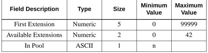
The Building database is shared with other Sentry applications, so you might not have to build it for Annoyance Trap. You will receive a message from the APM if you try to create the Building database and it already exists.The Building database contains a list of extensions and the location of each extension. A building location can be associated with an individual numeric extension or a range of numeric extensions. A given building can have more than one record if all of the extensions located in it are not consecutive. Each building database record contains the following fields:
• First Phone - The first extension in the range of extensions.
• Last Phone - The last extension in the range of extensions.
• Building ID - An ASCII string containing the building location.
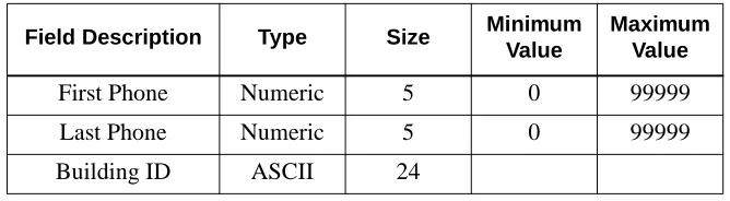
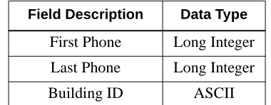
The Building master database is named “blding_m” by default and contains the following fields.
Table 3-1 Building Master Database Fields
The Building application database is named “blding” by default and contains the following fields.
Table 3-2 Building Application Database Fields
Field Description Type Size Minimum
Value
Maximum Value
First Phone Numeric 5 0 99999
Last Phone Numeric 5 0 99999
Building ID ASCII 24
Field Description Data Type