Optimization of Submarine Ring Stiffened
Composite Pressure Hull Using Numerical Methods
Afna Asif1, Jobil Varghese2
1
Civil Engineering Department, APJ Abdul Kalam Technological University, Mar Baselios Institute of Technology and Science Nellimattom, Ernakulam, India
2 Civil Engineering Department, APJ Abdul Kalam Technological University, Mar Baselios Institute of Technology and Science Nellimattom, Ernakulam, India
Abstract
In ocean exploration and sub-sea operation, the underwater vehicle is increasingly needed and is drawing more attention. The pressure hull is one of the main structures of the underwater vehicle, which provides load capacity for electronic systems and buoyancy for the carrier structure .The ring-stiffened hulls have better structural performances and are widely used in underwater vehicles and submarines. Three different composites such as CFRP, BFRP, GFRP were used to analyze the failure criteria to provide the optimum strength. The failure index of the orthotropic composite material should be less than one as per the Tsai-Wu Criteria. The carbon fiber reinforced polymer chosen to adopt the optimization technique. The material strength variation of pressure hull parameters based on Response surface optimization technique is carried out in ANSYS 17.0.
Keywords: Pressure hull, CFRP, GFRP, BFRP, Rules of Mixture,
Tsai-Wu Failure Criteria, Response surface optimization.
1. Introduction
The development of submarines in the future will keep on requiring designs to allow them to reach increasingly greater depths. Pressure hulls are one of the keys in the design of these vehicles. The problem is similar to other fields, like a vessel subjected to external pressure, which has to resist that load with the best possible design. The pressure hull is the inner hull of a submarine that maintains structural integrity with the difference between outside and inside pressure at depth. Modern submarines are usually cigar-shaped. This design, already visible on very early submarines is called a "teardrop hull", and was patterned after the bodies of whales. It significantly reduces the hydrodynamic drag on the submarine when submerged, but decreases the sea-keeping capabilities and increases the drag while surfaced. The concept of an outer hydro dynamically streamlined light hull separated from the inner pressure hull was first introduced in the early pioneering submarine in 1859. However, when military submarines
entered service in the early 1900s, the limitations of their propulsion systems forced them to operate on the surface most of the time; their hull designs were a compromise, with the outer hulls resembling a ship, allowing for good surface navigation, and a relatively streamlined superstructure to minimize drag under water. Because of the slow submerged speeds of these submarines, usually well below 10 knots (19 km/h), the increased drag for underwater travel by the conventional ship like outer hull was considered acceptable. Only late in World War II, when technology enhancements allowed faster and longer submerged operations and increased surveillance by enemy aircraft forced submarines to spend most of their times below the surface, did hull designs become teardrop shaped again, to reduce drag and noise. USS Albacore (AGSS-569) was a unique research submarine that pioneered the American version of the teardrop hull form (sometimes referred to as an "Albacore hull") of modern submarines. On modern military submarines the outer hull (and sometimes also the propeller) is covered with a thick layer of special sound-absorbing rubber, or anechoic plating, to make the submarine more difficult to detect by active and passive SONAR.
In this paper, the usage of composites in addition to FEM optimization techniques are the tools we have proposed in order to assess if the mistakes that may happen in these elements may have a better solution with composites instead of steel, avoiding costly modifications as in the case exposed.
2. Methodology
output parameters using Response surface optimization technique. The following procedure was adopted to optimize the composite pressure hull.
1. A pressure hull model[1] with a length of 1000mm were developed in ANSYS 17.0.
a) Rules of Mixture adopted to find the material properties like tensile strength, elastic modulus, density etc.
2. Different composites used to investigate their failure criteria to provide optimum strength. The basic details like cross sectional dimensions, number of stiffeners used are kept constant for all models.
3. Failure Criteria: - The stability and strength of the hull were checked with Tsai-Wu Failure Criteria. It predicts failure, when the failure index in a laminate reaches one. 4. Response Surface Optimization
a) The parameter set created with input and output variables.
b) Response surfaces for different parameter sets are modeled. After creating response surface, three candidate points are obtained as optimization points.
3. Pressure Hull
Inside the outer hull there is a strong hull, or pressure hull, which actually withstands the outside pressure and has normal atmospheric pressure inside. The pressure hull is generally constructed of thick high-strength steel with a complex structure and high strength reserve, and is separated with watertight bulkheads into several compartments. The pressure and light hulls aren't separated, and form a three-dimensional structure with increased strength. The inter hull space is used for some of the equipment which doesn't require constant pressure to operate. The list significantly differs between submarines, and generally includes different water/air tanks. In case of a single-hull submarine, the light hull and the pressure hull are the same except for the bow and stern.
The constructions of a pressure hull requires a high degree of precision. This is true irrespective of its size. Even a one inch (25 mm) deviation from cross-sectional roundness results in over 30 percent decrease of hydrostatic load. Minor deviations are resisted by the stiffener rings, and the total pressure force of several million longitudinally-oriented tons must be distributed evenly over the hull by using a hull with circular cross section. This design is the most resistant to compressive stress and without it no material could resist water pressure at submarine depths. Fig.1. shows the pressure vessel in a submarine. A submarine hull requires expensive transversal construction, with stiffener rings located more frequently than the longitudinal.
Fig.1 Typical pressure hull structure
3. Structural Model and Material Property
A ring-stiffened composite material pressure hull of an underwater vehicle designed for 2000 m water depth. It is composed of metal liner and outer winding fiber reinforced composite material. Inner ring frames are uniformly distributed. Length of the pressure hull L= 1000 mm, and the inner radius R =150 mm. Aluminum alloy is adopted for liner layer and the inner frame stiffeners, where the liner thickness is1 mm. Three different composites are selected to investigate the failure criteria. Matrix of the composite material is made of epoxy resin, and the reinforced fiber is carbon fiber (CFRP), Glass fiber (GFRP), Basalt (BFRP). In order to avoid the tension-bending coupling effects, 10 layers are symmetrically laminated and the material properties of the layers are same. Fig. 2 shows the sectional drawing of the pressure hull.
Fig.2 Sectional drawing
3.1 Rules of Mixture
property in the direction parallel to the fibers may be as high as
Ec = f Ef + (1-f) Em
(1)
Where,
• , is the volume fraction of the fibers
• Ef , is the elastic modulus of the fibers
• Em , is the elastic modulus of the matrix
In the case of the elastic modulus, this is known as the upper-bound modulus, and corresponds to loading parallel to the fibers. The inverse rule of mixtures states that in the direction perpendicular to the fibers, the elastic modulus of a composite can be as low as
Ec -1
(2)
If the property under study is the elastic modulus, this quantity is called the lower-bound modulus, and corresponds to a transverse loading. Material properties are demonstrated in Table 1.
Table 1: Material Properties of composites
4. FEM Analysis
Depending on the type of physics involved (static structural, modal structural, harmonic, random vibration, response spectrum) provides several means to control the solution of the physics simulation. Static Structural analysis determines the displacements, stresses, strains, and forces in structures or components caused by loads that do not induce significant inertia and damping effects. The submarine pressure hull were modeled with different composites to investigate their failure criteria to provide
optimum strength. The contact is provided as bonded (welded) connection. The boundary condition were provided as fixed supports at the ends. A design pressure of 30MPa uniformly distributed over the surface of hull for the analysis. The basic details like cross sectional dimensions, number of stiffeners used are kept constant for all models. Three models are created with different composites and analyzed in ANSYS 17.0 software. The composites are Carbon fiber (CFRP), Glass fiber(GFRP), and Basalt fiber(BFRP) reinforced polymers.
4.1 Tsai- Wu Failure Criteria
The Tsai–Wu failure criterion is a phenomenological material failure theory which is widely used for orthotropic composite materials which have different strengths in tension and compression[1] .The Tsai-Wu criterion predicts failure when the failure index in a laminate reaches one. This failure criterion is a specialization of the general quadratic failure criterion. In this paper, Tsai-Wu criteria is adopted to evaluate the failure of the composite material. The failure index of orthotropic composite material under plane stress is expressed by the following formula, where Fi and Fij are the strength parameters of stress space.
Fc = F1σ1 + F2σ2 + F11σ12+ F22σ22 + F66σ62+ 2F12σ1σ2 <
1
(3)
The shell circumferential stress of liner layer at the midpoint of two neighbouring frames σ1 , shell axial stress
of liner layer at frames σ2 and frame stress σr are checked
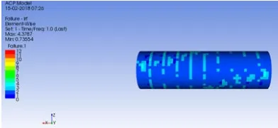
with aluminium alloy yield stress σs. Fig.3,4 & 5 shows the
Failure index of the CFRP,GFRP, & BFRP. We limited the failure index range as ten instead of one for the convenience and visibility of every point.
Fig.3. Failure index of the CFRP
Reinforcemen t Material
Strain at Break(%)
Tensile Strength
(MPa)
Elastic Modulus
(GPa)
GFRP 1.2-3.1 480-1600 35-51
BFRP 1.6-3.0 1035-1650 45-59
Fig.4. Failure index of the GFRP
Fig.5. Failure index of the BFRP
Comparing the results of failure, the carbon fibers, glass fiber and basalt fiber shows 4.3787, 8.0292, 5.9967 as failure index respectively and are safe with resect to Tsai-Wu Failure criteria.. The CFRP fiber shows better results as compared with the GFRP and BFRP fiber in case of failure index. Thus CFRP model selected to apply the response surface optimization.
4.2 Parameter Set
A parameter is an entity that is linked to a data model property within an application. You can have input and output parameters. An input parameter can be modified at the project level and drives a change within the data model. The value of an output parameter is set by the application, based on the current results or state. Input parameters are parameters that define the geometry or inputs to the analysis for the system under investigation. Input parameters have predefined values or ranges that may be changed. The input parameters include length, radius, dimensions of stiffeners, thickness, pressure, material properties etc. Output parameters are parameters that result from the geometry or are the response outputs from the analysis. These include (but are not limited to) body mass, deformation, stress, failure index etc. Custom Parameters are input or output parameters you have created and that are defined by an expression.
4.3 Response Surface Optimization
Response Surface Method (RSM) is a collection of statistical and mathematical techniques useful for developing, improving, and optimizing processes in which a response of interest is influenced by several variables and the objective is to optimize this response. In most RSM problems, a form of the relationship between the response and the independent variables is unknown. Once the important factors have been identified, the next step is to determine the settings for these factors that result in the optimum value of the response. The optimum value of the response may either be a maximum value or a minimum value, depending upon the product or process in question.
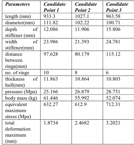
After creating response surfaces for different parameter sets such as length and diameter of hull, width and depth of stiffeners, distance between rings and number of rings, thickness of hull and pressure , three candidate points are obtained as optimization points. It shows minimum values for output parameters such as body mass, equivalent stress, and total deformation as the optimized values. Fig.6. shows the candidate points with the optimized values of input and output parameters. Table 2 demonstrates the optimized values of input and output parameters.
Table 2 Optimized values of input and output parameters
Parameters Candidate Point 1
Candidate Point 2
Candidate Point 3
length (mm) 933.3 1027.1 963.58 diameter(mm) 111.82 102.22 100.71 depth of
stiffener (mm)
12.086 11.906 15.806
width of stiffener(mm)
23.986 21.393 24.781
distance between rings(mm)
97.628 80.179 115.12
no. of rings 10 8 6
thickness of hull(mm)
11.863 10.864 10.803
pressure (Mpa) 25.166 26.879 28.751 body mass (kg) 61.446 55.992 52.074 equivalent
maximum stress (Mpa)
632.27 612.9 712.31
total deformation maximum (mm)
Fig.6. Candidate points with the optimized values of input and output parameters.
5. Conclusions
In this paper, Tsai-Wu criteria is adopted to evaluate the failure of the composite material. The Tsai-Wu criterion predicts failure when the failure index in a laminate reaches one. The CFRP fiber shows better results as compared with the GFRP and BFRP fiber in case of failure index. In composites, the matrix is usually a polymer resin, such as epoxy, to bind the reinforcements together. The reinforcement will give the CFRP its strength and rigidity; measured by stress and elastic modulus respectively. Unlike isotropic materials like steel and aluminum, CFRP has directional strength properties. The properties of CFRP depend on the layouts of the carbon fiber and the proportion of the carbon fibers relative to the polymer. CFRP have higher tensile strength with lower density comparing with the others. It results a better performance regarding the failure index. The carbon fiber is selected as the material for the pressure hull model as per the comparison between BFRP and GFRP. The parameter set created with input and output variables. The input parameters include length, diameter, dimensions of stiffeners, thickness and pressure. Output parameters include body mass, deformation and stress. Response surfaces for different parameter sets are modeled. After creating response surface, three candidate points are obtained as optimization points. It shows minimum values for output parameters such as body mass, equivalent stress, and total deformation as the optimized values
Acknowledgments
I express my deepest sense of gratitude to Mr. Jobil Varghese, Asst. Professor, MBITS, Nellimattom, my esteemed guide and my cordial thanks for his warm encouragement, thoughtful guidance, insightful decision, critical comments and correction of the thesis. I also express my sincere thanks to all the faculty members and students of the Civil Engineering Department of Mar Baselios Institute of Technology and Science for their co-operation and support.
References
[1] Bin Li, Yong-jie Pang, Yan-xue Cheng, Xiao-meng Zhu, “Collaborative optimization of ring stiffened composite pressure hull of underwater vehicle based on
lamination parameters”, International Journal of Naval
Architecture and Ocean Engineering 9 (2017) 373-381. [2] K. Sahitya Raju, Dr. S. Srinivas Rao, “Design optimisation of a composite cylindrical pressure vessel
using FEA”, International Journal of Scientific and
Research Publications, Volume 5, Issue 12, December 2015.
[3] J.Francoa, A.Corza, A.Peñab, “Optimization of pressure hulls of composite Materials” ECCM16 – 16th European Conference on Composite Materials, Spain, 22-26 June 2014.
[4] Elsayed Fathallah, Hui Qi,1 Lili Tong, and Mahmoud Helal1, “Design Optimization of Composite Elliptical Deep-Submersible Pressure Hull for Minimizing the
Buoyancy Factor”, Civil Engineering Department, M.T.C.
Kobry Elkobba, Cairo 11787, Egypt (2014).
[5] R.MacKay a,b,n, Fredvan Keulen, “Partial safety
factor approach to the design of submarine pressure hulls
using nonlinear finite element analysis”, Finite Elements
in Analysis and Design, 65 (2013) 1–16.
[6] S. Gohari, A. Golshan, M. Mostakhdemin, F. Mozafari, and A. Momenzadeh, “Failure strength of thin-walled cylindrical GFRP composite Shell against static internal and external pressure for various Volumetric fiber
fraction”, International Journal of Applied Physics and
Mathematics, Vol. 2, No. 2, March 2012.
[7] M. Buragohain and R. Velmurugan, “Optimal design of filament wound grid-stiffened Composite cylindrical
structures”, Defence Science Journal, Vol. 61, No. 1,
January 2011, pp. 88-94.
[8] Lei Zu , Sotiris Koussios, Adriaan Beukers, “Shape optimization of filament wound articulated pressure
vessels based on non-geodesic trajectories”, Composite
Structures 92 (2010) 339–346.
[9] J.Y. Zheng, P.F. Liu, “Elasto-plastic stress analysis and burst strength evaluation of Al-carbon fiber/epoxy
composite cylindrical laminates”, Computational
Materials Science 42 (2008) 453–461.
[10] Derek Graham, “Predicting the collapse of externally pressurised ring-stiffened cylinders using finite element
analysis”, Marine Structures 20 (2007) 202–217
[11] Cho-Chung Liang, Hung-Wen Chen b, Chan-Yung Jen, “Optimum design of filament-wound multilayer
sandwich submersible pressure hulls”, Ocean Engineering
30 (2003) 1941–1967.
more than one longitudinal buckling half-wave”, Journal of Ship Research, Vol. 19, No. 1, March 1975, pp. 18-22. [13] S. Adali, E. B. Summers & V. E. Verijenko,
“Optimisation of laminated cylindrical pressure vessels
under strength criterion”, Composite Structures 25 (1993)
305-312.
[14] G. J. Simitses and M. Aswani,“Minimum-Weight Design of Stiffened Cylinders Under Hydrostatic
Pressure”, Journal of Ship Research, No.4 ,Vol 21, Dec.
1977, pp. 217-224.
[15] Derek Graham,“Composite pressure hulls for deep
ocean Submersibles”, Composite Structures 32 (199.5)